This is a sort of an append-only history of details of the camera project. After I get all the software and server hardware running, I should make a nice concise writeup of the whole thing. Someday.


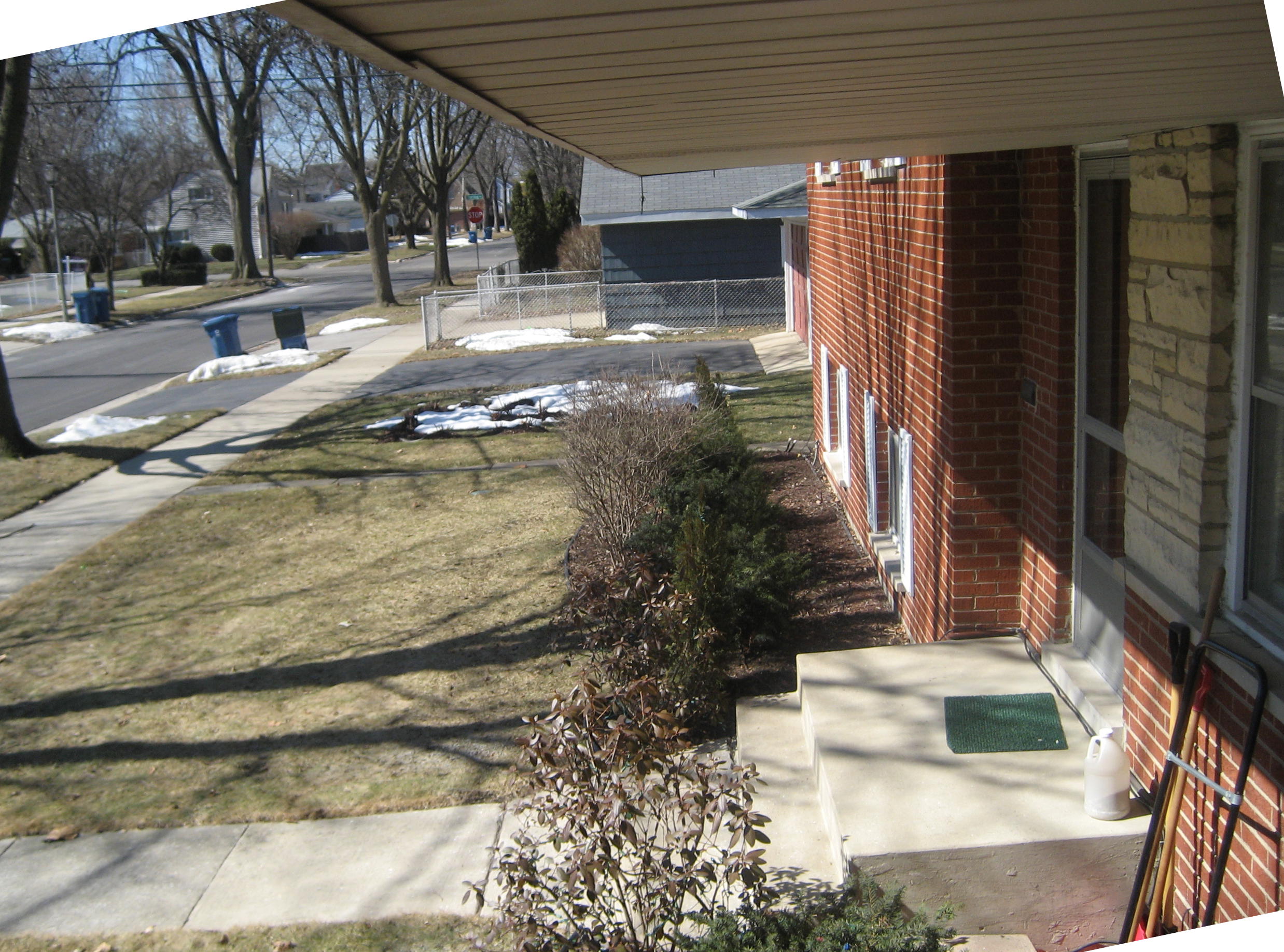
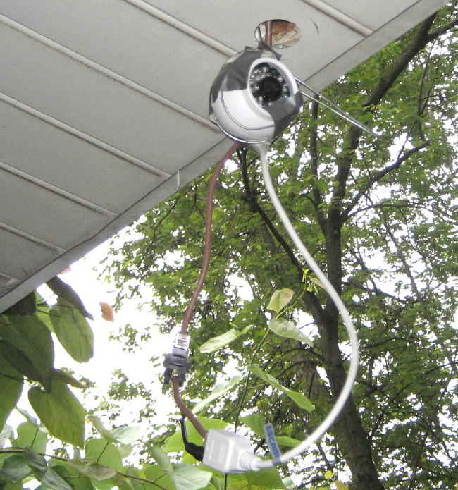
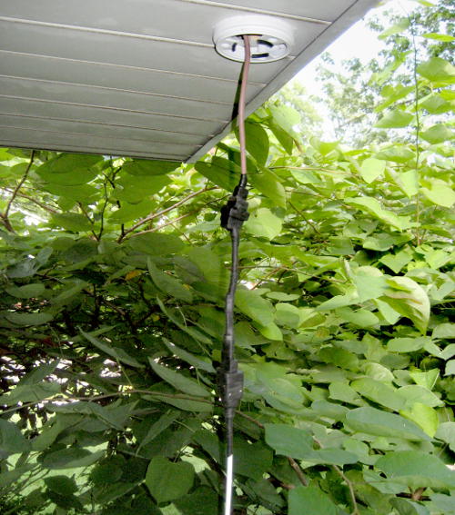
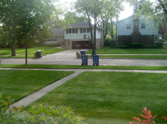
I’ve about given up on trying to mount a security camera in a tree in the parkway outside the house, even though it would have exactly the view I’d like the camera to have. Power is the issue – I could get the data to the house by radio. If instead I mount the camera under corner of the generous eave overhang, I can get a workable picture, and I can get wires to the camera! Pics here taken with my SD600 on the end of a stick, probably considerably different lens than the actual camera.
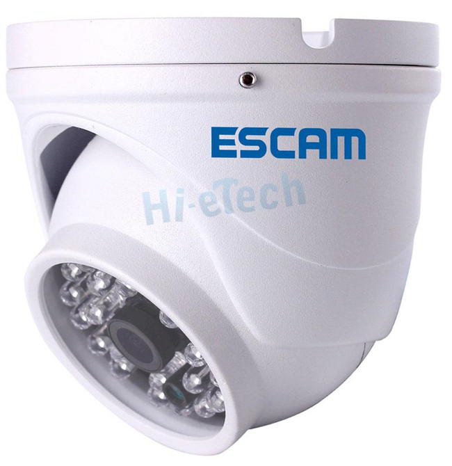
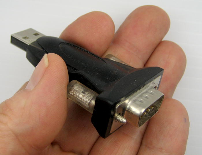
I got an Escam QD 520 Peashooter 720p wired IP camera for $36/free on Ebay. It supports ONVIF open protocol, so I hope to be able to cobble together something to grab snapshots every 10 minutes or whatever. It defaults to 192.168.1.10, so I had to put a machine on that net to talk to it initially. The camera contains a web server that requires Active-X, so IE is best. With that, I reset its IP to 192.168.99.222 and tried it on the home network. Pointing IE to it seems to provide a ‘live’ feed. I’ve also been able to get VLC on the main PC to display the video (with more delay) using rtsp://192.168.99.222:554//user=admin&password=&channel=1&stream=0.sdp. There’s also an ONVIF viewer app I can run on my phone or tablet.
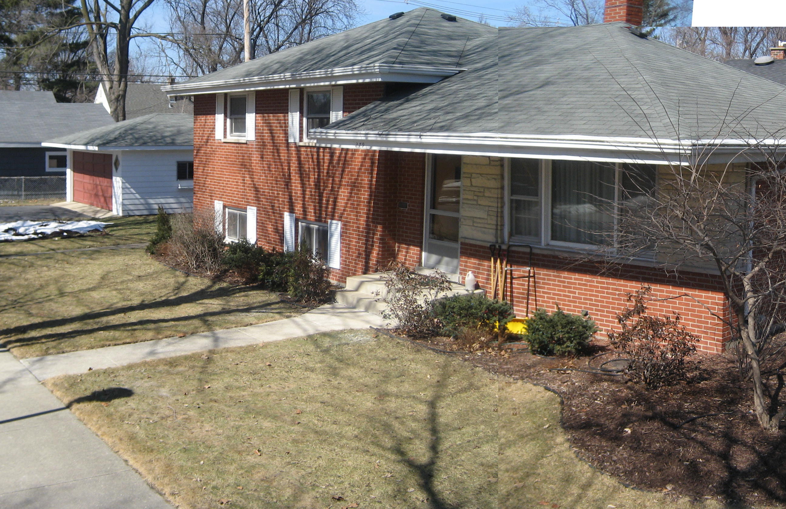
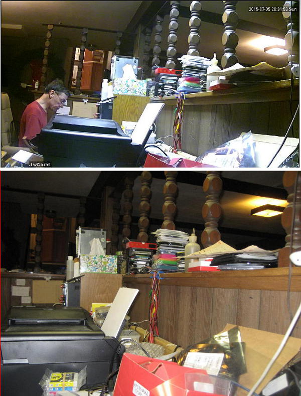
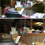 OK, let’s get some idea how the 2 camera lenses compare. Here are pics from the same place (Escam is from 2″ lower than my SD600), matched at right edge, scaled to same width. Original Escam was 970×540. The Escam (top) gives a slightly wider but much shorter field of view. With that lens comparison info and the outside pics above, I think I could move the camera a little closer to the door (but still as close to the outside edge of the overhang as possible). I might have to give up a sliver of sky, but should still get a very usable view.
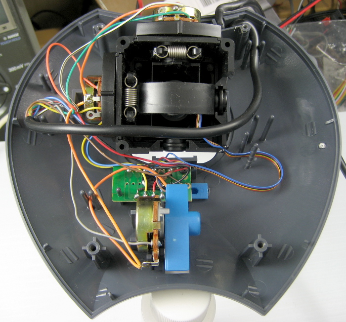
The camera seems pretty good (and seems to get good reviews) for the price. It’s color and has IR cut for more natural colors. It also has a light sensor and automatically switches to B/W mode and turns on its IR LEDs at night/low light. That seems to work in an indoor test. There’s an audible click when it changes over – which I suspect is mechanically moving the IR cut filter. The IR LEDs glow dim red, which some reviewers looking for a stealth night camera have complained about, but isn’t a concern for me.
Software
I’ve seen a couple of references to getting a jpeg snapshot with something like this:
ffmpeg -ss 2 -i rtsp://ip:554/h264_2 -y -f image2 -sameq -t 5 /path/to/output/$MONT/$DATE/$DATETIME.jpeg
None of the ffmpeg binaries on my Win7 machine support rtsp protocol. I installed it on the Dell Mini 9, but now it’s out of disk and doesn’t work well. One more thing on the list.
Wiring
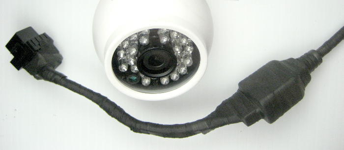
I made up a pair of passive POE adapters, using the brown/white pair bonded for +, blue/white for ground, with 2.1mm barrel connectors to match the camera’s connector. (Orange/white, green/white are straight thru for the network.) Seems to work with a 50′ patch cable between the adapters. I figured the actual run at maybe 70′, so it’s probably OK. I considered running a piece of lamp cord along with the Cat 5E for power, but I think I can get away with DC over those other 2 pairs. I was a little reluctant to add the pair of RJ45 connectors – one essentially outside, though protected – but went that way for convenience of assembly, testing, repair, etc.
I got 100′ of brown Cat5E solid for the run. Working in the attic won’t be fun, and I don’t really know how I’m going to get to the corner where the camera will be located. I could probably take the USB-camera-on-a-cable up there with a laptop (or the Win8.1 tablet?), snake it down between the roof and the wall top plate on the end of a stick (8′ furring strip?) and get a reasonable view of what’s down there above the soffit, but that would probably cost an extra trip to the attic. It would be really nice if I could make it all in one trip.
There’s already a piece of Cat5 run in the attic and thru the soffit right in the corner near the front door – diagonally opposite where I need it – but I can’t figure any way to use that to save the dreaded trip into the attic.
OK – I finessed some aluminum soffit down (thanks for the suggestion, Ed!) to get a look under it and found – wood. There’s sheathing (presumably the old soffit) under all the aluminum near where the camera will be mounted – and probably everywhere else, as well. Yeah, yeah, there must be some kind of vent holes – maybe only near the vented aluminum panel? The good news is that I can mount the camera with longish wood screws instead of just sheet metal screws into the aluminum. There’s 1/2″ between the main flat areas of the aluminum and the wood above, but I’ll deal with that later.
That means I can’t see what’s above that wood until I go thru it (and thru the aluminum!) Ed suggested a hole saw – good idea – but since I’m working so close to the outside edge of the soffit, to locate the hole I need to know where the rafters are. (Or more accurately where the “soffit bearers” tying the rafter ends to the wall are.) Maybe I can find the nails that attach the fascia board to them? Yes! I 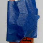 made a nail finder by taping a nice hard disk magnet to a yard stick. Sweeping that along the fascia board, it stuck very satisfyingly to (what I presume are) the nails holding the fascia to the rafter ends. Very sensibly and conveniently, the aluminum fascia is attached with aluminum nails, so I don’t even get false positives from those. Now I know where not to cut my access hole!
Given no access to nice long fiberglass fish poles, one possible approach for pulling the wire would be to plop a magnet on the end of a pull string up just inside the access hole, and fish for it with a magnet on the end of a 8′ furring strip that also had the USB camera attached by heading for the daylight. If I can see any. Maybe stick an index card up thru the hole to make a larger lighted target? If I could set that up before I went into the attic, and if I could grab the end with the magnet and pull it up into the attic, I could tape the pull string to the end of the Cat5 I’d just run, leave enough slack nicely laid out so it would pull smoothly, go down and pull the wire with the string, and never have to go back into the attic! If.
Progress!
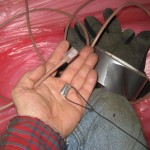
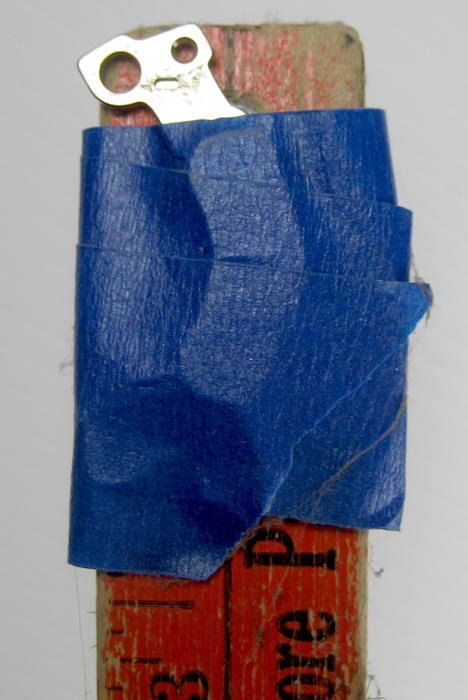
 Here’s the magnet taped to the end of my 8′ furring strip “fishing pole”. I left the original mounting bracket on and bent it hoping to bring the field lines from the stick surface of the magnet closer to the exposed surface, hoping to make it more attractive to the magnet on the pull string. Time to go up to the attic.
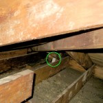 Here’s the view down into the soffit – much less obstructed that I’d feared. (No USB-camera-on-a-wire needed.) You can see the card I stuck thru the hole. That worked out well. It’s waaay over there, appropriate for having located the hole as close to the corner (where I originally wanted the camera) as I dared put it, considering the as yet unseen rafters, etc. Time to go fishing.
 I never heard a ‘clunk’ of the magnets getting together, but they did, and on the first try. And here’s the phase 1 payoff picture: The end of the successfully fished pull string and the cable it’s
 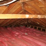 about to be taped to! I was hoping for a selfie of me working in that corner of the attic, but it was way too unpleasant to bother setting it up. Here’s the after-the-fact picture of the disturbed insulation where I was working. It was beautifully laid down before. You can just barely see the Cat5 to the camera sloppily running across the top of the insulation.
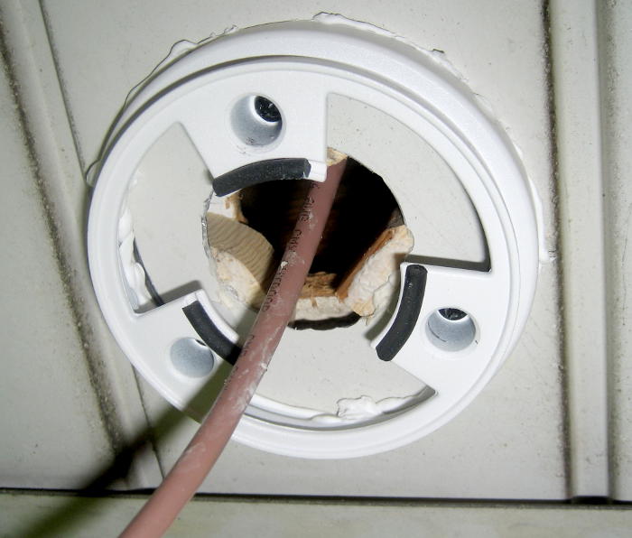
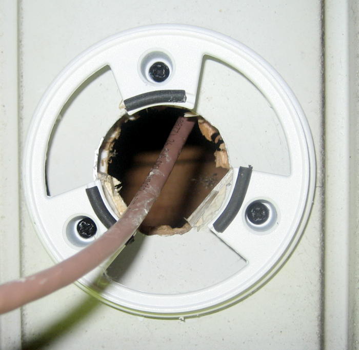
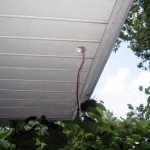 And here’s a beautiful thing! Some might just see it as yet another hole in the house, or another wire dangling out of something. But those of us who have been there and done that know it’s a
 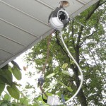 Beautiful Thing.
Of course I had to see if I could actually get pictures over the new cable, so I hung the camera from a piece of baling wire, the crude POE pigtail dangling. It works!
As I got the parts assembled, thought and rethought what I’d need to optimize that unpleasant forray into the attic, collected intel about where I could/should put the hole, I came to feel real urgency to get closure on pulling that dumb wire. It was a huge relief/satisfaction when I got it thru. Interestingly, now that it’s pulled, my feelings about actually mounting the camera and getting that all sealed up are much more “pretty soon, when I get around to it”. I still don’t understand how my head works.
Getting pictures
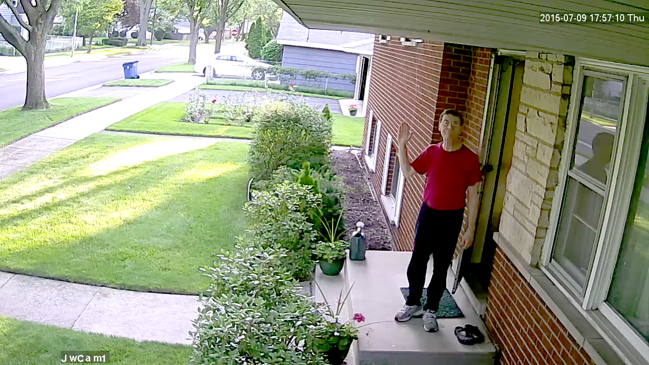
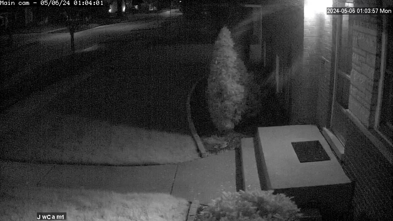
The software that comes with the Escam includes a viewer that runs on IE (only) thru an unsigned Chinese Active X plugin. It provides access to quite a variety of config parameters in the camera itself, including the critical IP address. It displays video  streamed from the camera, and can record it. There’s a snapshot button, but it always reports failure. I did make a brief recording, played it through VLC, and used that tool’s snapshot feature to get the first actual still from the system. This is essentially what the final 1280×720 results will look like. I still have no snapshot software. It looks like cameras like this often have a jpeg snapshot mode, but after playing quite a bit, I’m pretty convinced that this camera just doesn’t support direct jpeg.
I downloaded an Onvifer app to my phone that takes advantage of the open ONVIF protocol the camera supports. Results – with the phone on wifi to the same segment the camera is on – are poor. You can see a picture, but it’s usually badly distorted, and performance is surprisingly poor. Fortunately, that wasn’t a target use case. VLC on the phone provides good, smooth video.
ONVIF is just a standard management protocol to talk to the camera for internal params, PanTiltZoom, etc. The actual streaming video goes over the also standard rtp over rtsp protocols. Fortunately, those are standard enough that VLC and many other streaming players can start and read them, using the rtsp:// URL above. The Onvifer dev replied to a rating comment I made on Playstore and included a pointer to the Windows app ONVIF Device Manager (hosted on the besmirched sourceforge). That very nice software can also talk to the camera (on 192.168.99.222:8899) and mess with most, but not all of the in-camera params. I guess only the supplied Chinese Active-X plugin supports all the local device extensions.
It’s quite interesting that now that there’s an actual video camera mounted up there, scope creep is rearing its head. (OK, it’s not actually mounted there yet. But Real Soon Now.) The vision – from way back when I thought I could get the camera in the tree – was to get a still picture maybe every 5 minutes. But maybe I should take advantage of the hardware and capture actual live video to some local storage. Maybe 24 hours at 1 frame/sec, rolling over automatically? Heck, storage is cheap. A 38 sec test recording at 5 F/s was 5.5 MB, or 13 GB/day. I guess thumbdrive flash isn’t suitable for the application, but I certainly have old hard disks that would hold that or a lot more. Or that no-longer-hot-stuff 230 GB USB-connected external hard disk. That’s 2 weeks @ 5 F/s! And I bet that spare PogoPlug could handle it and maybe even serve it! Of course there’s the question of how to make all that work, including snapshots, and freezing or archiving or something in case of emergency. “But that’s just software.”
Looking at memory needed for stills, a jpeg compressed 16:1 compared to a png looked really good at 200% display in gimp. That jpeg (still 1280×720) was 90KB. The latest plus one/hr for 24 hours is 2.3MB – trivial even if I pushed them up to my hosting account. Or I could just host them on the Pogo. Decisions, decisions.
If I want to serve from a machine at home: I had some free DDNS service, but I had to log in every so often to keep it active. For the access I need to the home server, keeping a bookmark in my phone, laptop, tablet with just the IP address is probably good enough, especially given that the U-verse IP address doesn’t change often. Heck, I could just put the home IP address off in a corner of the main HA page.
Mounted!
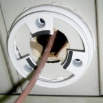 To get a sound mounting for the base, I put three 1/2″ thick wood blocks (with holes for the screws) between the aluminum soffit and the old soffit board. The screws went through the soffit board, and it’s nicely solid. I put silicone caulk under the edge, mainly to fill 3 wire chase holes, but later realized there’s such a gap between the camera ball and the big fixed part of the base
  that the caulk was a waste of time.
Unfortunately, the ends of the blocks covered enough of the hole that I couldn’t fit the connectors thru any more. A little work with a chisel made the hole usable, if even uglier.
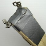
To best protect the two RJ-45 connections that would live forever above the soffit, I took 2 steps. 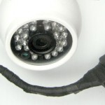 First, I sprayed the actual contacts with Caig Pro Gold G5 snake oil. (I suppose I should write up my actively conflicted reactions to that stuff some time.)
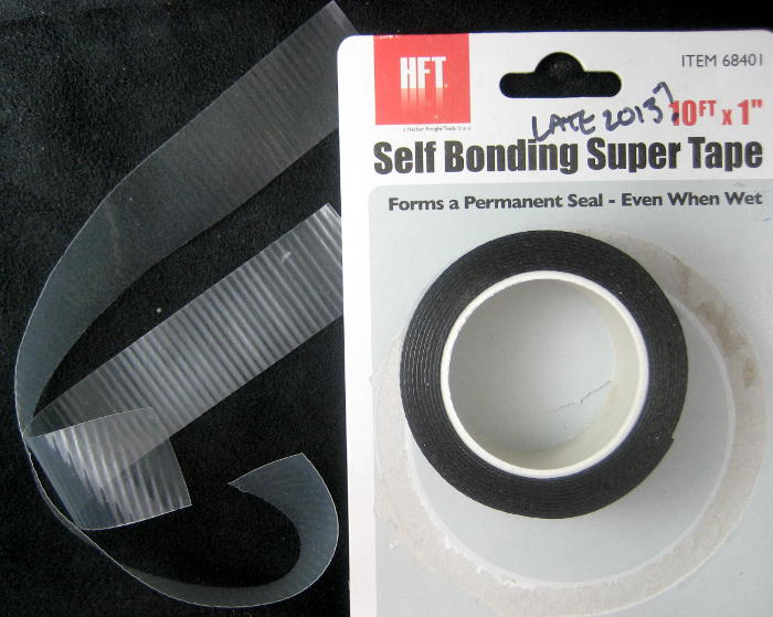
 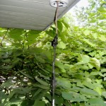 As outermost protection, I wrapped the whole thing – Cat 5 cable, POE splitter, OEM camera connector – with self bonding silicone tape. First I did the easy part – camera and splitter – at the comfort of my bench. Then I plugged the cable in and did the rest on a ladder outside. A bit of incompletely wiped off snake oil softened/compromised some of the self bonding tape over the punch-down RJ female into which the cable was plugged. Hope it lasts OK.
 The first part took just 10″ of tape; the outside part 5.5″. It was easy to come up with those numbers after the fact by measuring the backing liner from the 2 pieces.
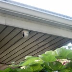 The final assembly was almost anticlimactic. I’d managed to do things in the right order, and by that time I could get good live video on my phone, so even the last bit of aiming/alignment was easy to do standing on the ladder. The soffit doesn’t look stained like that to the naked eye – not sure what caused that. But the outside (and attic) work is all done! Now it’s just computers and software. 🙂
Online!
Update 7/26/16: Just (barely) in time for our Kirkwood vacation, I have snapshots every 2 minutes from the camera, hosted on the Pogo. Looks like our outside IP address thru U-verse is pretty stable. Some look-up-my-ip site showed it as a static address. I set up a cron script to check it and email me if it ever changes. Anyway, a bookmark to that IP address in phone, tablets, laptop should be fine to find it even without DDNS.
I used a shell script calling avconv (successor to ffmpeg) to get the snapshots. The camera doesn’t seem to serve the brief new sessions to get those snapshots if it is also streaming, so probably no 24×7 video capture. Boo.
And in an inappropriate fit of boldness, I hacked my main home automation stuff to push the latest image out to the web server on my hosting account, and added a link at the very top of the page to the picture. It seems to work, but changing both the main HA program and the main web page was a very brash thing to do hours before leaving home on vacation.
Update 10/19/15: I just checked the latest pic, and it was from a day ago. OK – now what? I restarted the cron job on the Pogo with all watering turned off yesterday – could that have done it? Then I realized I had zero recollection of how the snapshots worked. Here are the current ugly details.
The script ~/gosnaps running on the Dell Mini reads from the camera and writes a snapshot every 2 minutes to a hard coded path on the locally attached Free Agent external drive. (I had unplugged the drive – wondering why it was plugged in – to use the mini as a portable controller for the watering while shutting it down yesterday. I saw no need to plug it back in. Wrong. Dumb, but wrong.) Gosnaps calls ~/putpic which ftps the latest pic to the Pogo, twice: once with its timestamp name (like snap10-19-13-16.jpg), again as “latest.jpg”. The hack referred to above is to 485pollC.pl to ftp latest.jpg up to the hosting server. There’s a cron job on the Pogo to clean out pics older than 2 days, but nothing on the mini to clean off the Free Agent! Fortunately, it looks like it’ll take a long time to fill it up. Plugging the external drive back in seems to have fixed it. Ubuntu automagically remounted it – thanks!
It’s a crude and non-resilient way to do it, but at least next time I’ll be able to look it up here. (Which, after all, is why these notes are here!) I guess I wanted to keep some pics, but didn’t want to thrash flash on a thumb drive or something. I think I was reluctant to host it on the Pogo out of performance fears which I didn’t have time to confirm/allay. Hopefully I’ll put something more appropriate in place before I break it again.
Update 7/26/16 ~2AM: I happened to notice that the “latest.jpg” was from 12:53 on 7/25/16 (yesterday). After chasing a bit (doing ps and df on jimsdellmini and the pogo) it looked like nothing was out of disk, and gosnaps was still running. I was very pleased to find these notes so I had a clue how this stuff worked. Very suspicious was that there was a lot of stuff dated 7/25/15 – just a year ago. Was there a collision since the timestamps had no year? I think even when there’s a crash, files should just get overwritten, so I think that shouldn’t be a problem.
There was a comment in gosnaps saying
# Added timelimit in hopes of avoiding problem where avconv hangs for days if
# it can’t connect or something. Not tested 🙁 12/3/15 jw
and it looked like avconv had a valid “-timelimit 60”, to kill after one minute. There was a running avconv process:
jim 8940 3482 0 Jul25 ? 00:00:57 avconv -v quiet -timelimit 60 -vframes 20 -i rtsp://192.168.99.222:554//user=admin&password=&channel=1&stream=0.sdp -vsync 1 -q:v 15 -r 0.1 -t 1 -y /media/FreeAgent Drive/pics/snap07-25-12-55.jpg
– trying to write the next pic after the stuck one. I killed that process, and it all started working again. I hate to have to put yet another watchdog in to manage hung avconv processes, but if it happens while we’re out of town it would take an awkward double ssh session to get into jimsdellmini to fix it.
I suppose an additional watchdog on the GoDaddy host to check for old pic wouldn’t be too hard (as there are a couple already). <checks wd2.pl script> Oops – there’s already one there – with a threshold of 21 minutes. <checks for text on phone> Why didn’t it trigger? Ahh – I bet the pogo kept sending the same “latest.jpg”, thus updating the timestamp on the host, which is what the script checks for. I guess that script functions correctly to catch failure of the pogo to send pics – just doesn’t check the actual time of the pic.
Yeah, I suppose I could include a timestamp file as well as the jpeg, yada, yada. Ugh. I suppose the next approach would be a cron script on jimsdellmini to check for a hung avconv process, try to kill it, and report. Ugh. Or maybe just check for old timestamp on latest.jpg, try to pkill avconv, and send a text. Shouldn’t be too hard. Hmm – looks like jimsdellmini doesn’t know how to send text and email yet. Still shouldn’t be too hard. Of course, based on the timestamp in the comment, the problem has only happened about every 6 months. How much effort do I want to put into it? Of course if I’m on vacation when it happens… Ugh. But at least it’s running again today, and I know a pkill has some chance of fixing it.
Update 8/30/17: This is a dup of an update to the “resurrecting the pogo” post. I’ve been fighting on and off with being out of storage on the “camera drive” on jimsdell mini. It’s been running a 1GB thumb drive for a while, and just failed again. Thankfully the “house picture old” watchdog fired and sent email. Turns out once again the drive was full. There’s a cron job purging files matching a find -mtime +30, but that wasn’t aggressive enough. After I manually deleted several days’ worth of pics, it started working again. How many days’ worth will the drive hold? It looks like nite pics are ~26KB, while day pics are more like 110KB. Doing on ls |wc gave 10586 files, while df showed 658048K used. So that averages about 62KB/pic. At 24*30 pics/day, we burn about 45MB/day, so the 1GB drive should hold around 22 days of pics. I changed the cron job to -mtime +15, so it should take care of itself now, and run around 30% free. We’ll see.
Update 2/20/18: File space on the little camera drive is stable.
The camera proved extremely useful to support worry about snow removal while we were in Texas for a couple of weeks. I’m not pretty interested in having more views.
After resolving a flurry of worry about my new iSmart C8018DN2 P2P camera exposing itself to malware with a firewall rule blocking all outgoing from its static IP, plus telling it both its gateway and both DNS servers were its own IP (that sucka ain’t gonna talk to nobody outside), I thought to worry about the ESCAM. I used the sniffer cable I’d used for the iSmart and watched its traffic. Nothing scary at all. Some harmless ARP and bursts of RTP traffic every 2 minutes. Good.
In the process, I checked and discovered that it does in fact have an open telnet daemon. With the help of my friend Google, I discovered its root password was xmhdipc. Very interesting, tho not useful. 7/21/19: Wrong. Since I can’t get in with the original unsigned Active X plugin any more, I can’t set the date. But logging in (yes, root/xmhdipc) gave a linux environment, and the date command worked with immediate effect to change the on-video date. Yay!
Update 8/6/18 on camera software: The snapshot processing train has failed from time to time. Running out of disk space is a popular cause, but a hung avconv is a more insidious one after dumb disk management problems have been resolved.
Troubleshooting that has progressed, and there’s currently a section in gosnaps in the initial comments on finding a hung avconv, and even a script (gofix) to try to fix it. I’ve made a couple of attempts at using some kind of timeout to keep avconv from hanging, but only added the linux sledgehammer facility timeout a few days ago. This post is to document the possibility of a best case outcome that avconv doesn’t hang the snapshot system ever again. (Of course, there’s a datestamped commend in gosnaps with that change as well.) We’ll see.

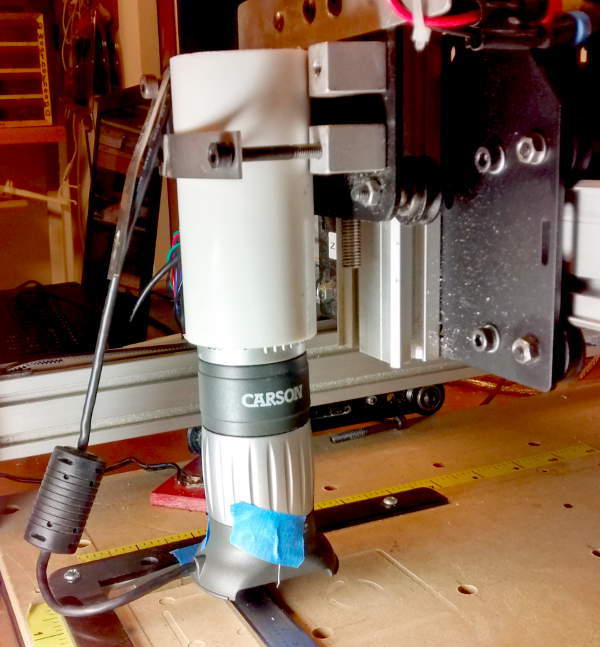 The microscope friction fit perfectly in a scrap of PVC pipe we clamped in place of the spindle. As a “crosshair”, we taped a .007″ strand of hookup wire across the bottom of the ‘scope. We found we needed
  more light than the little built-in LEDs provided when we zoomed in like we wanted, so we clamped a reflector lamp near by to provide that light. Here’s the whole setup.
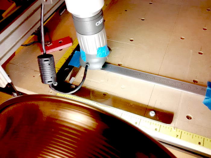 had that caliper. It went back together perfectly after the testing.
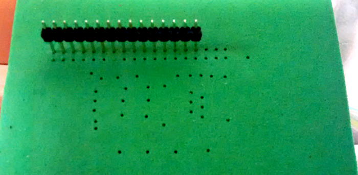
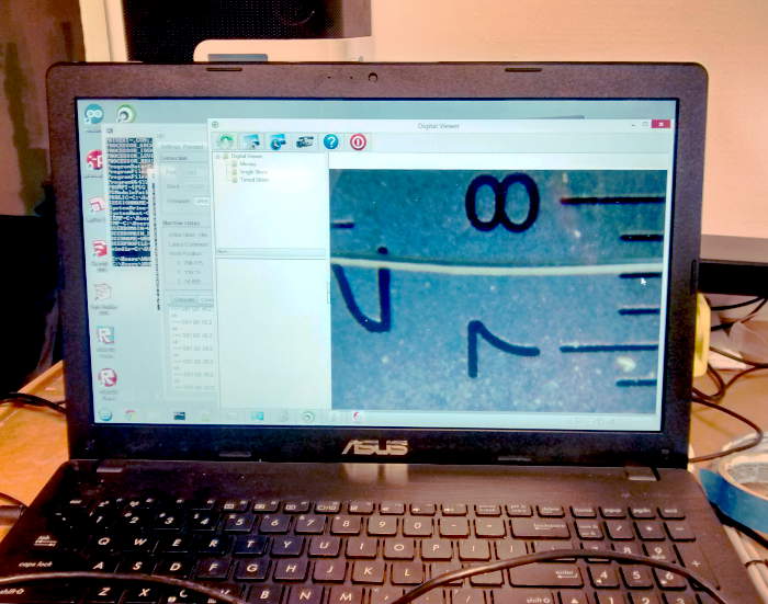 The image from the ‘scope was very nice. The white stripe is the crosshair wire. A finer wire would have been even better. The marks shown are spaced at 0.025″.
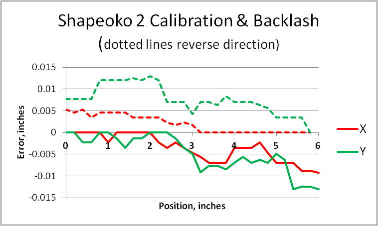 The dotted lines are coming back in the reverse direction (toward X|Y=0). Observations:
 so far – drilling PCBs – the results are “interesting”. With holes from my favorite #64 drill at about 0.039″ diameter (black circle), the average absolute error in X (red) of about 0.0028″ and even worst error of 0.0053″ aren’t bad at all. The Y (green) average error of 0.0062″ isn’t too bad, but the worst case error of 0.013″ is a third of a hole diameter – worth some concern. (There must be a better way to present this visually.)
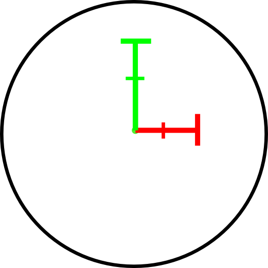


