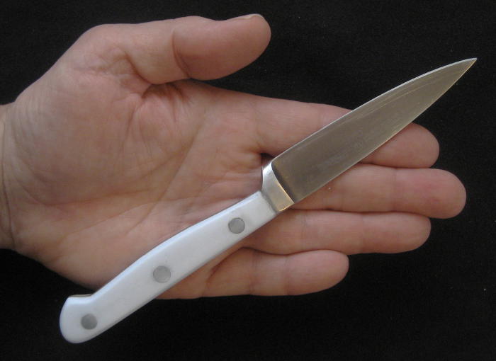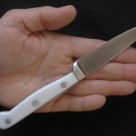
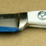
Many years ago, when we redid the kitchen largely in white, we got a couple of Wusthof White Classic knives. They were perfect (including fitting in with the decor), and were used daily. But one day the #4066 3.5″ paring knife mysteriously disappeared.
The Classic series was no longer available in white, so sadly, we did without. (The Ikon is available in ‘Creme’, but that’s not white and we didn’t like it as much, and while the Classic was still available in black, that didn’t go with the kitchen and the other white knife.) We got another white paring knife, and while quite serviceable, it just wasn’t the same. I watched Ebay and Craigslist on and off for several years, but never found a replacement. 🙁
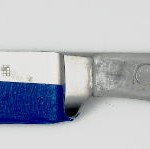
But you know, the handle is really just a couple of pieces of plastic somehow riveted on. The important part – the beautifully made blade and tang are still readily available – just with black handles. I bet I could make some white handles! I found a used one on Ebay to play with for $17 (they’re $40 new). It aged on the shelf for 6 months, and then I finally got started. Maybe I can make it a Christmas present for Lauren!
Disassembly
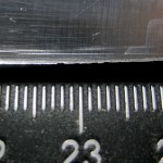
The big question was how the rivets were done. I found a Wusthof promo video on Youtube, and watched and rewatched the few seconds it devoted to the handles, but there wasn’t much there. I measured the visible heads on the remaining knife, and they were just 1/4″. That’s an unusual size for a German knife, but I’ll take it. I think I heard the rivets were stainless steel, and so ordered a piece of 1/4″ stainless steel rod.
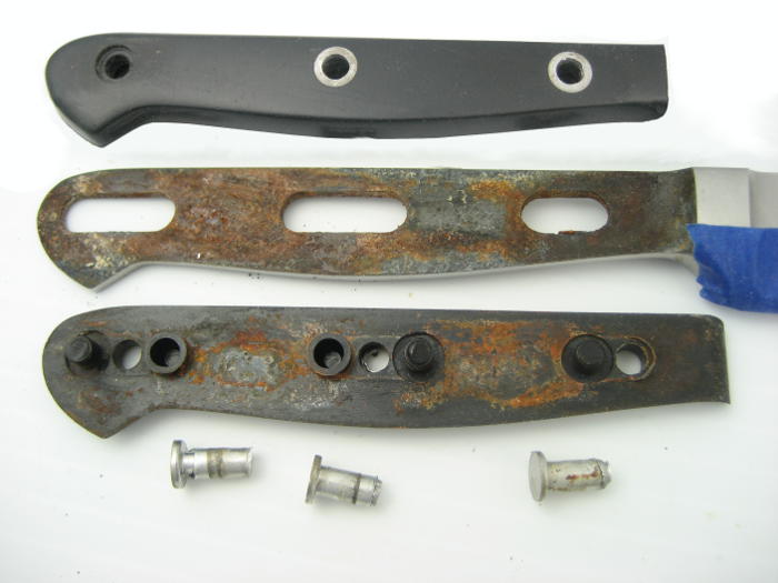
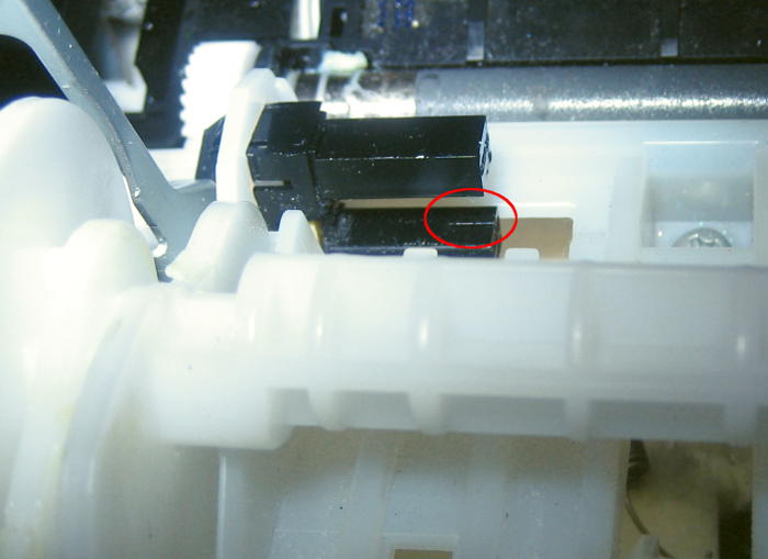
When I drilled out the first rivet, it was obvious that it was aluminum, not stainless. I drove it out, and it was a normal, 2-piece rivet! I drilled the others out and pried the scales (handle pieces) off. Although water had gotten in and caused some rust, things were generally in pretty good shape. But I expected round holes in the tang, not those interesting post and socket connections between the two scales!
New scales take shape
The plan was to epoxy the scales on (probably to the horror of any real knife folks reading this). That made the “rivets” really just cosmetic (but of course required, to look like the original). Epoxying them in would be fine, and even add a little more reinforcement.
I got three pieces of 3/16″ white plastic – polypropylene, acetyl (Delrin), and uhmw polyethylene – from McMaster Carr to play with. Somehow I heard polypropylene might be what they used, so that’s what I tried first.
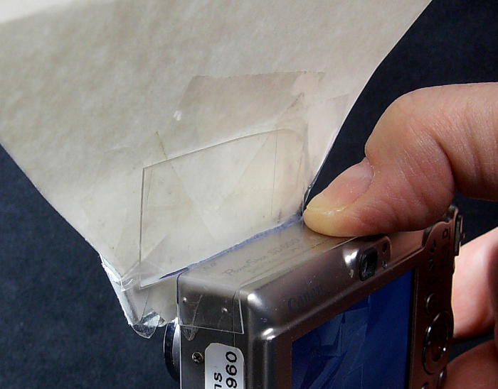
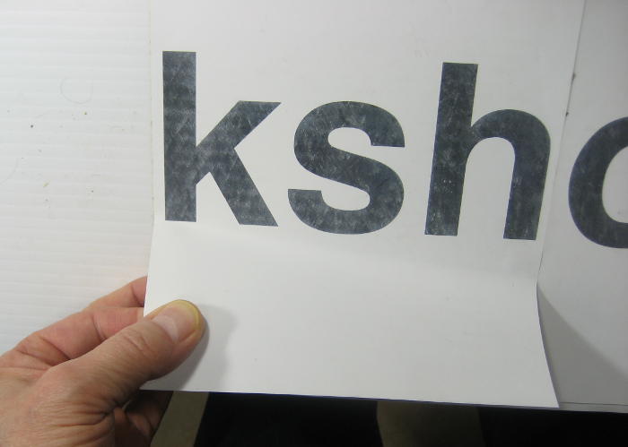
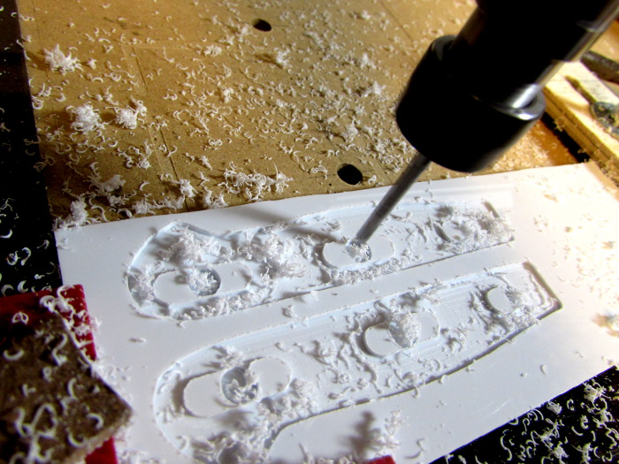
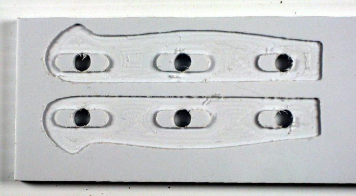
You know, if I machined little islands on the new scales – less than half the tang thickness – to fit into those oval holes, I bet the scales would be a whole lot more  secure. And I bet the Shapeoko 2 could do that! I took a picture of the tang from straight above and quite high so as to avoid parallax problems, imported it into Inkscape, converted to SVG, added circles for the rivets, and mirrored it. It apparently imported into Easel just fine. I tweaked the depth of cut to drill out the holes completely, but just cut the rest down 0.04″.
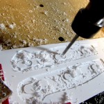 I fired up the SO2 with its brand new Carvey-style auto Z touchoff, clamped a chunk of the poly down and clicked Start Carving. It worked!
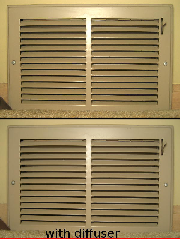
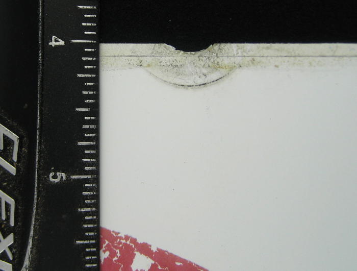
Well, almost. The SVG had 2 paths for the handle outlines, 6 for the islands, plus 6 for the holes. Apparently either Easel or I 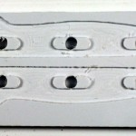 bumped the top group of islands+holes down just a little. You can see that they’re slightly closer to the handle outline than in the bottom one. The tang fit pretty well into the bottom one, but required quite a bit of handwork on the top one before it fit. Boo.
I’m mostly blaming Easel for that. I selected the islands as a group while setting up the depths of cut. Maybe I unintentionally moved them a bit while I was just trying to select them. I’d consider blaming Easel for that for not having more hysteresis when selecting without moving. Or maybe Easel moved the group by itself – sort of snapping to some invisible, secret grid. That’s definitely their fault. (I have some other evidence of that as well. As soon as I do some more testing and reproduce it, I’ll raise it as a bug or change request with Easel.)
Hindsight shows the whole issue never needed to occur: There’s absolutely no reason to have the outline of the tang even represented in the machining. All that’s required are the islands and holes. If I’d realized that, instead of trying for a quite precise fit, I would have made a much more generous outline. Live and learn.
Starting to look like a knife
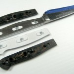
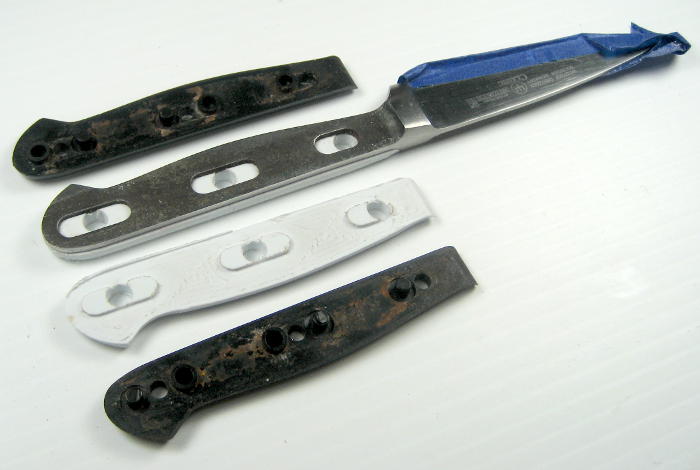
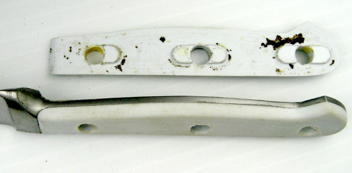
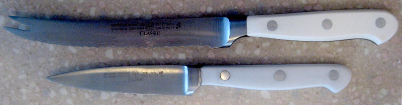
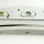
 I cut the pieces apart, carefully hand-fitted them to the bolster, and roughed the outline to match the tang. Here they are posing with the originals they’ll replace. To make it easier to rough sand/file the outline down, I temporarily bolted them on. Much easier to work on both together, plus it provided a motivating, tantalizing preview of what it will look like.
It was Christmas Eve morning and I had to get it finished by tomorrow! I hadn’t been 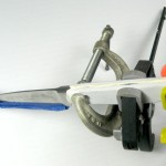 able to find any aluminum rod locally, so I had to go to the space to machine down some aluminum scrap for the “rivets”. And the white marine epoxy I planned to use to help hide oopses took several hours to cure, so I better do that before I go. I did some final trimming of the fitted surfaces, cleaned them with alcohol, mixed and applied the epoxy and clamped it all up. Hmm – that’s more like off-white – but it’ll do. Off to the space.
When I came back (with a slightly undersized 1/4″ aluminum rod – oops) the epoxy was mostly set up, but far from hard. The package said 3 hours to handle, 12 hours for max strength. I didn’t have that much time, so I decided to speed the curing along by putting it in the oven. I dunno – how about 240F? Fortunately I checked the specs of the plastic on McMaster Carr, and it’s only good up to 180F. Oops – backed the oven down to 165.
When I pulled it out of the oven maybe an hour and a half later, the good news was that the epoxy was pretty well set up. The bad news was that since I’d removed the clamps, the plastic had expanded and bowed, and was now a good 1/8″ away from the tang in some places. (Sorry, no picture. I was sad and mad and desperate and just started ripping it apart to see what I could salvage.)
The epoxy stuck admirably to the tang. Fortunately, it was pretty easy and appropriate to file that off, so that cleanup wasn’t too bad. The mixed news – good for recovering the scales, not so good for overall confidence in the epoxy holding the scales on for 10 years – was that since the handles were polypropylene, the epoxy didn’t stick very well. Never saw that coming. Boo on me. But at least the cleanup went pretty fast.
Round 2
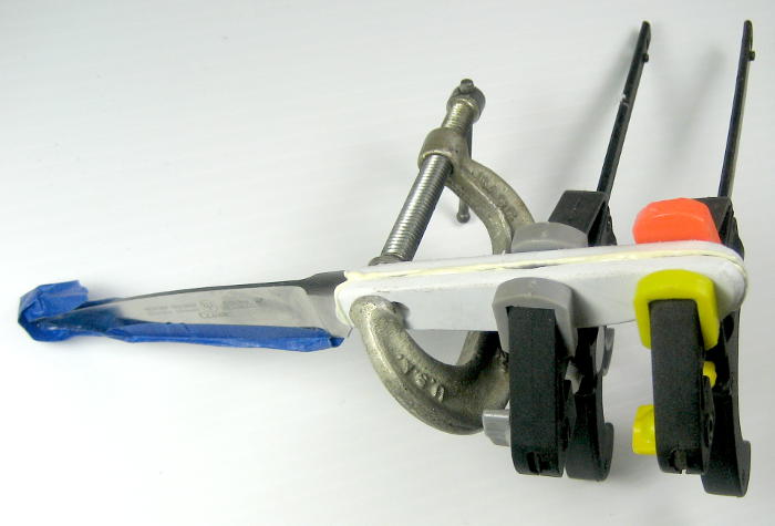
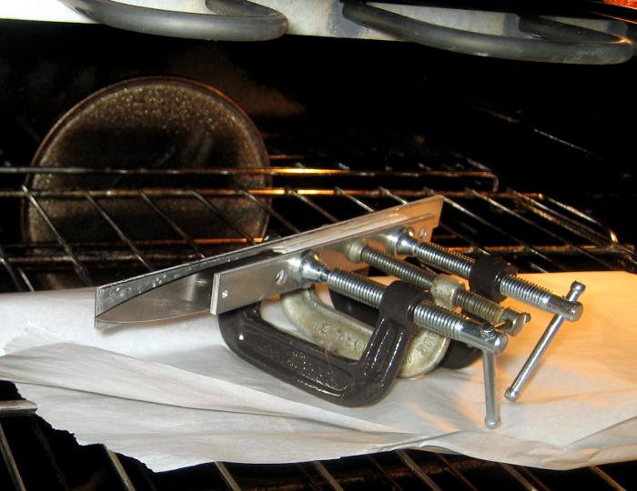
I’ve heard that flame-treating the surface of polyethylene – like just passing a propane torch over it – chemically alters the surface temporarily such that epoxy will stick better. (See note on this at the end.) It was worth a 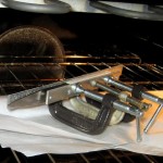 try with cousin polypropylene, so after the new round of dry fitting and cleaning with alcohol, I flamed the surfaces to be epoxied. With time running out, this time I used all metal clamps and put it directly into the oven (at 170F). I also put some aluminum plates over the scales, in hopes of keeping them straighter and tighter.
When I took it out maybe 4 hours later, it was fine. The epoxy had set up very nicely and the scales were flat and in place. All the rivet holes were plugged pretty solid with epoxy, but that should be easy to drill out. It was starting to feel like a knife in my hand.
Sanding
I’d trimmed the scales pretty close to size with a file, but it was getting time for more precise fitting, so I switched to sandpaper. Just as I’d expected, the (dry) 100-150 grit paper got me closer to a good fit, but left a terrible finish, and ground dirt into the nice white handle. I’d read up some, and it looked like wet sanding should work. I’d never done any wet sanding, but had picked up some wet/dry paper – up to 3000 grit! – on the way home from the space. I’d been of the opinion that anything beyond maybe 400 grit was only for nutcases. (I was wrong.)
I started wet sanding with 220, and then moved to 500. I was delighted and relieved that the finer grit and water actually left a clean (as well as smooth) finish. But I could still see some file marks. I understand the drill – back to the 220. File marks gone – 500 – then 1000. It was an interesting learning experience, and it was producing the results I’d hoped for.
So close
It was 6 o’clock Christmas morning, and I’d gotten thru 1000 grit wet sanding, and the knife was looking and feeling very good. Better deal with the rivets before I do final polishing. The bit of aluminum stock I’d turned at the space was uneven in diameter. I’d gotten carried away making rough cut passes on the lathe, and forgot to check the size. On the partial pass when it dawned on me that I should measure, the part of it not yet cut was actually very close to 0.25″, though the portion I’d done the last rough pass on was noticeably under that. Overall the 2.5″ of rod had 3 different diameters. I was going to have to hand fit each of the rivets. Fine.
I drilled the epoxy out of the holes with a 15/64″ bit and started to play with the aluminum. The thin part of the rod was quite loose in the holes. I cut a piece a little longer than one rivet needed to be and banged on it lengthwise with a hammer and anvil. Sure enough, it shortened and fattened up. I was surprised that the ends were somewhat mushroomed rather than a uniform fattening. But it fit better. I’ll take it! One down.
 I drilled the middle hole out to 1/4″ and started to fit the fattest part of the rod for the second rivet. It was a little tight, and stuck. I tapped the end of the rod on the anvil to knock it back out. To my stunned amazement, one of the scales came off, with the rod still stuck in it. I’d just been handling the knife a lot, sanding, dunking in water, and was very comfortable that it was now one piece forever. But Not.
A little numb (and tired), I finished fitting the rivets, re-flamed the scale, and stuck it all back together (including the rivets) with 5 minute epoxy. I have no idea how well it will hold up in real use, but I should at least be able to make something that looks decent for Lauren. I had to keep reminding myself that this was essentially the first prototype, and I’d gotten much farther than with many first protos. OK, if I have to start over (maybe with the Delrin?), I’ll know a whole lot more about how to do this.
 After the epoxy set up, I carefully filed the rivets down flush with the surface of the handle, then (dry) sanded them so they’d (almost) pass a fingernail test. It was sad to see the pristine surface the 1000 grit wet paper had left trashed, but now I had faith that the wet sanding would make it nice again.
So close – again
Back to the now-familiar wet sanding, and I could feel my technique improving. This wet sanding stuff is OK. I was up to 1000, maybe 1200, and it was time for our earlier than usual Christmas dinner. I wasn’t going to be able to finish in time. Boo.
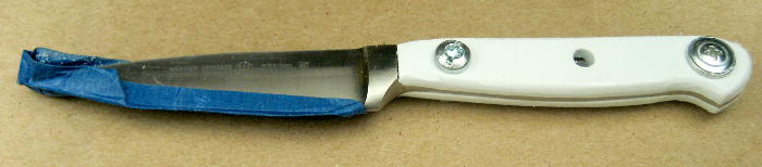
After dinner I decided to show it to her in its handle-not polished, unsharpened, incomplete state (though it did have rivets). Fortunately, to the eyes and fingers of someone who hadn’t been watching every scratch and rough place as it progressed from grit to grit, it looked and felt pretty nice. Showing it at that point turned out well, and she graciously gave me full credit. 🙂 It also meant the self-imposed pressure was off, and I could take a very needed nap instead of running back down to the basement to work on it some more. I should be able to finish it up tomorrow.
(a few days later) I’d cut my thumb and didn’t really want to soak it sanding, so I took a couple of days off. When I got back to it, I went back and forth and even went back to 500 with a sanding block to get the rivets more flush. The problem was always with dark particles from the aluminum sticking in the scratches in the plastic and making it look dirty. I ended up with 2500 and even some Novus #1, but the effect was still there. It got less pronounced as the grits got finer, but the final answer was judiciously sanding/polishing around the rivets to clean it up. It never got perfect, but it did get done. I think burnishing it with a fingernail was the last step.
Sharpening
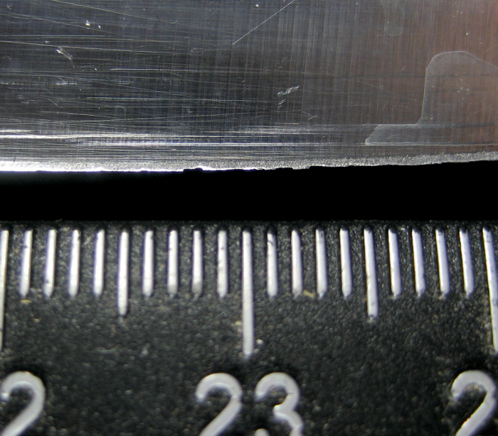
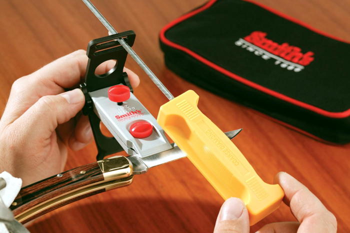
 When I received the used knife, it wasn’t surprising to find the blade in bad shape. It had several visible nicks in the edge, so some serious material removal would be needed. I used that as justification to get a Smith’s 4 stone diamond precision (DFPK) sharpening system ($50). Rods screwed into the stone holders keep
 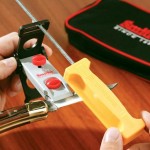 the angle constant, and should keep the nice blade from looking like it had been sloppily sharpened.
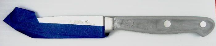
As soon as I got it home I tried to use it on the little Victorinox knife I always carry, but the blade was too small to fit in the clamp. I can come up with something to make it work, and I will some day, so this initial fail won’t count much against it. (See update.)
(a few days later) OK, it’s all done, and I’m pretty much a fan of the Smith system. I started with the coarse diamond hone and took quite a bit of metal off to get the nicks out. I had watched a bunch of videos on sharpening – mostly with this or it sister Lansky system – and found near religious advice about counting the number of strokes on each side and making sure they were identical, or even guys saying the guys advising 10 strokes on one side 10 on the other were wrong and it should be 1 on one side, 1 on the other. When the grinding is measured in minutes rather than strokes, some of those comments seem extreme.
I went thru the coarse and fine diamond hones, trying to keep the grinding on the 2 sides balanced. But I ended up using a fingernail to feel for the burr to decide which side needed the last few strokes. Using a loupe, I found the last inch or so near the point was still very dull even after what I thought had been uniform work with both hones all the way to the tip. Some more concentrated work fixed that pretty quickly.
The clamp did leave a mark on the Wusthof blade, as well as on the white (painted??) blade on the white paring knife it replaced. I took the fine diamond hone to the clamping surfaces and found the likely culprit. I doubt it will leave any more marks. Too bad I wasn’t clever enough to do that before I sharpened the good knife. Live and learn.
While I could feel and hear the difference between the coarse and fine hones, it was a startling step to the Arkansas fine stone. It was clear that this was a polishing tool. That too was very welcome. My old Spyderco SharpMaker is nice for polishing, but the consistent angle plus wide range of grits available make the Smith’s a much more powerful and versatile tool. And the white knife is really sharp as it goes into service. (Several other knives got dramatically improved as well.)
Done!
(12/30/14) I’m completely happy with how it cuts (as I expected all along), the handles haven’t fallen off yet, it looks acceptable to the casual viewer and feels very nice in your hand. You can still see dark smudges around the rivets, and they don’t pass a fingernail test like the ones on the real knife do. Careful inspection shows some irregularities at some seams, and you can 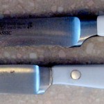 see epoxy in more than one place. The color of the plastic is noticeably cooler than and not quite as bright as the handles of the real Wusthof White Classic it lives next to. But it’s fully satisfactory and officially in service, the interim white paring knife has been retired (though sharp!), I’ve learned a lot, and the project is Done!
Note on flame treating polyethylene
Wow. I read up a little about flame treating, hoping to learn whether it helped polypropylene as well as polyethylene. The flame treatment’s action of increasing the surface energy of Low Surface Energy materials like PE and PP allows the epoxy to “wet” the surface better, and thus adhere better. It’s not specific to epoxy – it allows the surface to be wetted better by any liquid.
Well, that should be easy to test. So I took a polyethylene cutting board (cheap source of 3/8″ HDPE stock from Walmart) and played the flame from a propane torch over a strip in the middle for a few seconds. When I ran water over it, the water beaded up and rolled off just as you would expect – everywhere except where I’d played the flame. In that area, the water sheeted and wet the plastic. It was completely unmistakable. I tried it on a piece of the PP I’d made the handles from, making a video clip as I did, and the effect was very clear on that as well. Here’s the clip. Wow – it really works!
The one additional step I’ve run across (but never tried) is wet sanding the still uncured epoxy into the (flame treated) surface to get it even more intimately in contact. I’d really like to do a decent set of tensile strength tests, with enough samples to get a handle on the statistics, a few surface treatment styles, and a few epoxies from HF 5 minute cheapie to G-Flex. Some real experience with epoxying polyethylene would be quite valuable. Might even be worth writing up for Make:. Great – like I need another project on the list. 🙂
Update: Sharpening small Victorinox
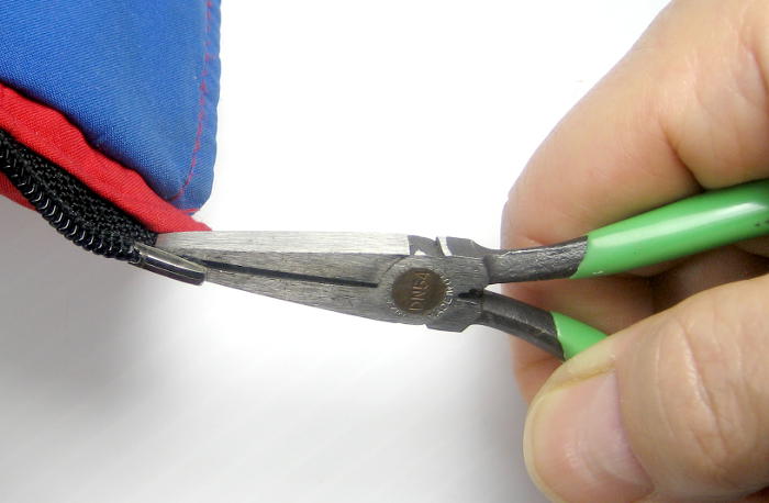
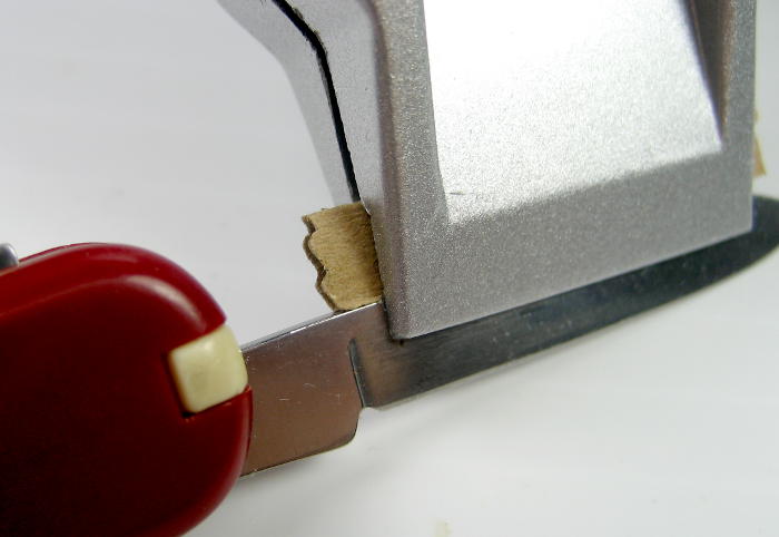
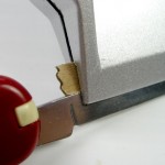 I went back and found a simple way to clamp the small blade of the Victorinox in the sharpener. (It sharpened up very nicely.) A little scrap of thin corrugated cardboard kept the blade from sliding back in the clamp. The problem (without that spacer) was that even if the clamp jaws were perfectly parallel with the blade taper, if the blade moved back at all it got looser, then completely loose.
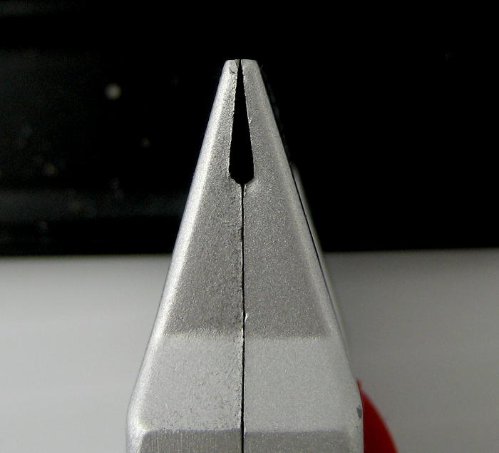
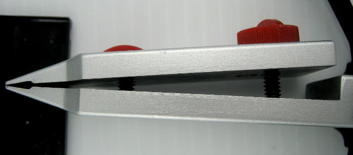
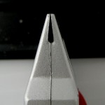 The clamp is (very appropriately and even elegantly) designed to accommodate tapered blade spines. The screw near the blade acts as an adjustable pivot for the clamp to fit various blade thicknesses/tapers.
  (Yeah, it’s a single adjustment to deal with two separate variables, so some user savvy is required.) The clamping action is done by the back screw. It was
 annoying humorous to see redneck reviewers complain about not being able to tighten the front screw to clamp the blade. Well, duh – that’s not what it’s for.

 I’ve often wished for stable camera mount above the bench where I take a lot of project pictures. It needed to be quite flexible in where it could locate the camera, but still fairly rigid for say good registration of an HDR series. After several months of intermittently mulling over lots of approaches, I ended up with something that’s simple, effective, and doesn’t add a lot of extra hardware to my overcrowded shop.
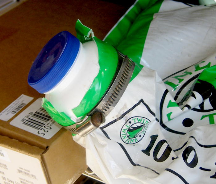
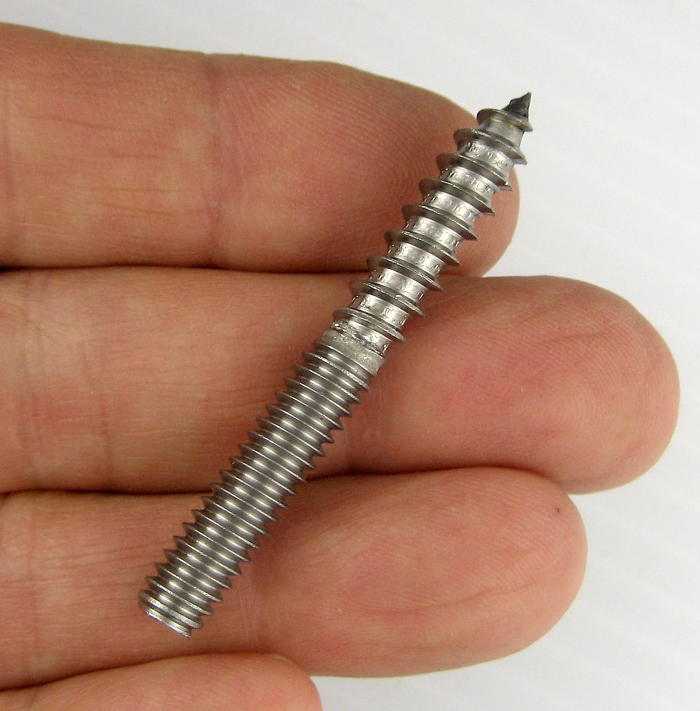 A hanger bolt was the answer. Took a little tweaking to get the right length and the thumbscrew on the tripod head in the right place, but no rocket science.
 Works great.
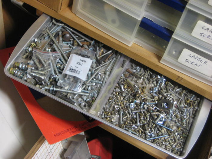 (It ended up in the ‘assorted bolts’ tray, still in its poly bag. That tray embodies the fundamental storage precept that containers of jumbled stuff should never be deeper than maybe twice the typical dimension of the ‘stuff’ they contain.)