
We use Nomorobo for our VOIP home phone, and I’m very happy with the service. (NMR: Your phone provider’s simultaneous ring service routes calls to both your phone and NMR. If NMR decides it’s bad, they pick up, and you hear only that first ring.)
But you know, if we could just skip the first ring on all incoming calls to our phones, all the annoying one-ring NMR blocks would go away. (Yeah, they’re much better than having the call come thru, but still annoying.) Yes, it would make legit callers endure one more ring before we answered, and I’m willing to make them pay that cost. But then we could always get up to check the phone on the first ring instead of wondering. Sounds like a winner!
A Plan forms
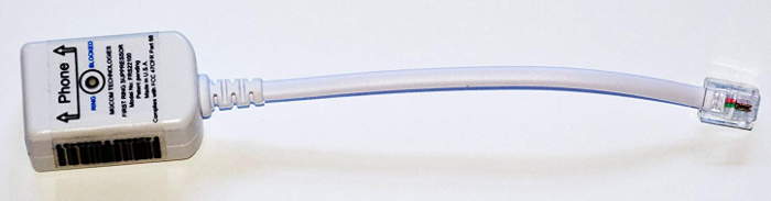 So I found the MGCOM FRS22100 Nomorobo first ring blocker. Self powered, 5 stars on Amazon. Perfect – I’ll buy one today! Except that you can’t. No longer available. And my best Google-fu couldn’t find any NOS or even used ones on Ebay. Bummer.
I wrote to the company, but never heard back from them.
A New Plan forms
OK – this is just telephone stuff. I should be able to make one. Yeah, Yet Another Project – but it would stop all those rings! And how hard can it be? (Famous Last Words)
The device needs to be right after the VOIP controller/modem. (That last portion before the phone jack is the Analog Telephone Adapter, or ATA. Thanks, David!) Caller ID info is sent between 1st and 2nd rings (in Bell 202 FSK here in the US). If I could disconnect all the house phones as the first ring starts quickly enough that the phones don’t start to ring, and if I reconnected just after that ring, but before the caller ID, (and if the phone doesn’t barf at losing 48V), I think that would work.
The best solution
Since absolutely all the stuff that comes out the RJ11 phone jack on the back of the Xfinity gateway is generated inside that box – not coming thru miles of copper outside – there’s a perfect place to implement no-first-ring: in the software in the gateway. It would just be a couple of lines of code. But that’s not gonna happen. Easier to just build some hardware. 🙁
Not quite POTS
Real Plain Old Telephone Service is formally not ground referenced. But while what comes out of our Xfinity VOIP gateway has to look a lot like analog POTS to work with whatever phones people hook up to it, it doesn’t have to play by exactly the same rules, so I need to check it out.
I measured 48VDC across the line on-hook (as expected). There was ~10V same polarity off-hook – fine. On-hook, there was 3VDC from 3rd prong ground to one side and 51V to the other. Don’t know whether the gateway or our local phones did that. Grounded the 51V line arbitrarily thru 10KΩ, and it only dropped the voltage to maybe 46V, so there’s some actual connectivity to ground. So my stuff needs to be not ground referenced. Noted.
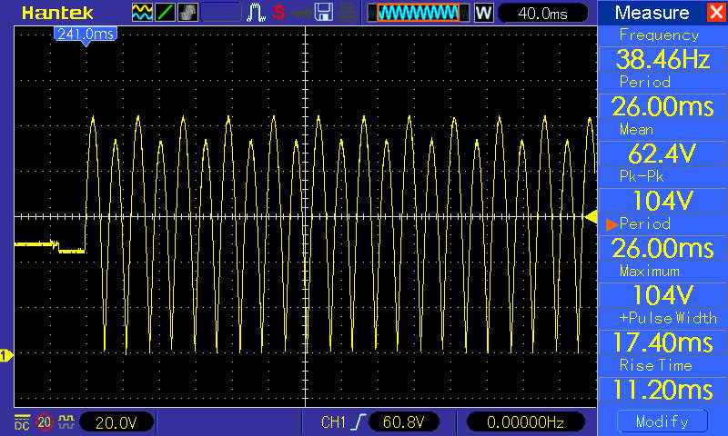 I need to see the actual voltage waveforms on the line to design the circuit. My shiny new Hantek DSO is perfectly suited to that task, but unfortunately, it’s ground referenced. An isolation transformer fixed that. I put a full wave bridge on the line (as described below) and recorded a ring. (I think this is the first pic directly recorded by the scope to USB I’ve used.) We see alternating amplitude of the half cycles, but not the 90VRMS superimposed on 48V we expect. It’s more like 70VRMS (200Vpp) on top of 5VDC. But now we know what we’re working with.
Timing
If the ring is 2 sec @20 Hz, that’s about 40 cycles (80 after full wave rectification). Each half cycle is 25ms. If the code + relay could react within say 5 ms (1/5 of a half cycle), I’d guess it would work. (Guess is the operative word: “The test is the test.”, as Ziggy would say.) But now I have a ballpark time budget target.
Relays
A relay seems the suitable way to disconnect/reconnect all the house phones. But the timing is critical: I have to sense the ring very quickly, and then open the circuit very quickly. And then at the end of the ring I have to reconnect before the caller ID starts. How fast is a relay?
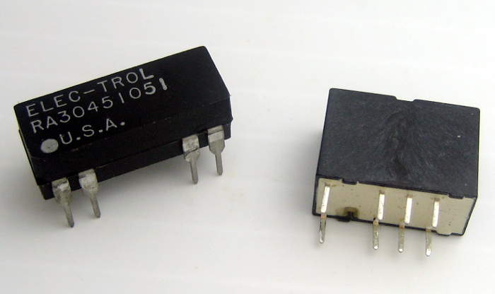 I checked out two small 5V relays from the junkbox. The first was clearly a reed switch – just SPST, and it reacted to a magnet nearby. The second was DPDT, so presumably had a more traditional mechanism inside.
The reed switch closed in ~150 µsec, with another 100 µsec of bounce. That’s plenty fast enough. Release time was harder to measure, but I think it’s ~10 µsec even at 5V. The second one had similar times – sorry for missing data. But they’re plenty fast enough. Surprise: The DPDT relay coil is polarity sensitive!
Failsafe
Having the phones stop working because some wall wart I used (or my code!) failed is unacceptable. So a failsafe design requires the relay to be normally closed, ruling out the reed switch. And if I have a pair of the DPDT contacts in parallel, it’s even more robust. We use the DPDT relay.
Circuit design
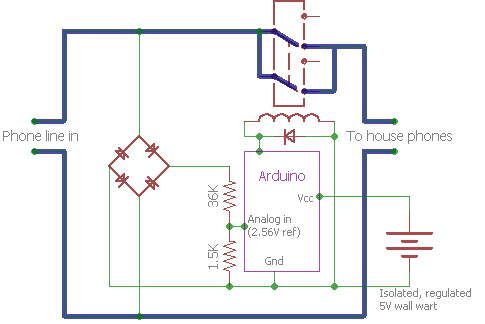 Let’s just start with a bridge rectifier on the line and use the negative output as local ground so we’re only dealing with one polarity. One side of the line to the rest of the house goes thru the NC relay contacts.
The observed ring voltage is ~104V max. (Every other half cycle is ~95V.) We can divide that down to work with say the 1.1V reference on an Arduino. We don’t get any additional info from anything over maybe the first maybe 10V (above 48), so exceeding the max of the A/D is OK, as long as we don’t exceed the abs max voltage on any pin (Vcc+0.5V). If it works, it’s just code from there. 🙂
Arduino data
The first prototyping was with a normal 328P Arduino Nano. I hooked up a bridge rectifier and voltage divider and had the  Arduino spew raw A/D values at 115200 to a laptop running on battery (and so isolated from ground). It uses 5V Aref instead of the intended 1.1V – oops. I suspect the circled part is the caller ID data. If so, I have around 600ms from ring stop to data. I can easily get the relay to close again in that time. I hope that’s enough for the phone to get over saying “What the heck just happened?” on losing 48V for a couple of seconds and listen for the ID. I hope it doesn’t expect a ring first… (It does.)
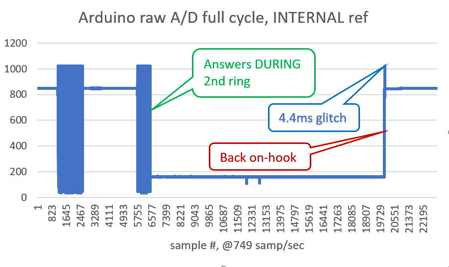 Here’s another run, of a full cycle including pickup, and with analogReference(INTERNAL). Interesting, but the real value is that now I can set my thresholds. The 48VDC idled at 848 counts, so how about 1020 for high threshold. Off-hook was 159. So say < 400 for that. (That glitch will bite us later.)
First proto
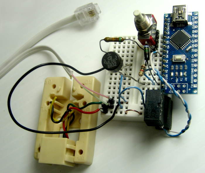 OK – made up a prototype. Remembered to put a diode across the coil. There’s still a button from the data collection runs, but it will go soon. While the contacts of the relay – if you want to parallel them as I do – are “breadboard friendly”, the coil contacts are not. Had to solder some leads on – grumpf. (And discovered they’re polarity sensitive!)
Both male and female phone connections are quite fragile, but with luck this will only have to survive or two connect/disconnect cycles. (Try a dozen.) The female is from an old DSL filter. That Nano with header pins along (only) one side has come in handy a couple of times.
First live observations
Took longer to get the code working than I hoped/expected. 🙂 Some dumb stuff, a math error (integer rolling average without roundoff correction), and a real logic error forgetting that line voltage goes very low (below off-hook threshold) every half-cycle of ring, which screwed up off-hook detection.
Grabbed a nice 5V wall wart and verified that it was properly isolated. While it showed 33VAC between output and line, with an arbitrary 10K in parallel with the meter that voltage went away nicely. We have power.
Caller ID issue
Phone behavior is a little different: It seems to announce the caller ID out loud when it didn’t before (although I had set it to do so). And it doesn’t display the caller ID until after the second (first heard) ring. I think that should be mostly OK. But it looks like it doesn’t listen for caller ID until it’s heard a ring, so my efforts to reconnect quickly to let that first caller ID thru were wasted. Boo.
But if it takes most of a ring to walk close enough to the phone to see the display, maybe the timing isn’t too much of a problem. I guess we’ll have to live with it a bit to see. (It’s fine.)
False positive glitch
 When I put the proto back in, going off hook and back on registered as a (1-ring) NMR block. Huh? Captured this directly from the phone line, starting off-hook, going on-hook. There’s a 10V (above 48V) glitch, probably enough to hit 1023 on the A/D and register as a ring. And this would happen every time we made an outgoing call (or presumably answered a legit call).
Looks like it happens 14ms after going on-hook. Yeah, the positive glitch is only about 4.4ms, but I hope that 35ms negative lump won’t mess anything else up. Looks like it’s probably low enough to register as off-hook (briefly). (I’m starting to love these scope captures!)
After most of a day stewing and messing with it, I realized that by simplifying the state machine in the code (rather than adding the two new states I was trying) it would all work. Simplifying is such a nice word.
Reporting
Immediately following the first mostly-successful test, alter ego Mr Data rose from repose wanting to know how many successful blocks had occurred. Shoulda known he’d ask that. Fine. But how to display it?
Yak shaving: LCD display
I’ve wanted an I2C LCD for a long time for just such situations. (With a keypad, but didn’t need it this time.) I dug around in the LCD box and found an I2C backpack laid out for 1602 LCDs. And a 1602. Could it be that easy?
Well, startlingly, yes. I soldered the backpack on, ran the I2C checker on it and it saw a device respond on addr 0x27. 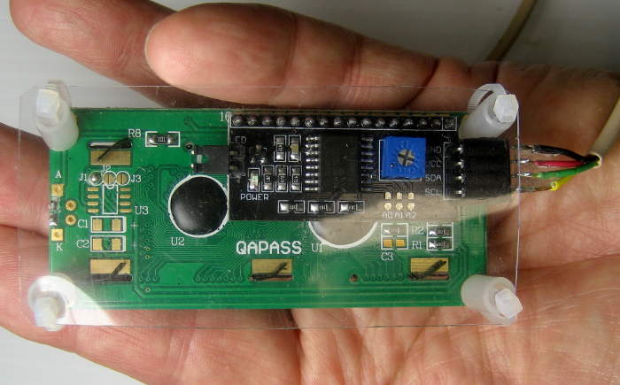 The chip on the backpack was a PCF8574. Looked up its addr – 0x27! Found a lib for it on my machine, ran the example code and it came up and showed stuff! Put a little protective PET backing on the module and started writing code.
Cut and pasted from the LCD example to the new Nomorobo2.ino (first saving the working version, as is proper). 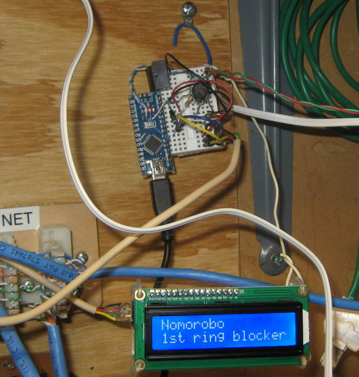 Added a few jumpers to support an I2C connector, loaded the code on it, and the display came up!
Wow – that was way quicker than it could have been. We have an operational proto with logging of rings blocked and NMR events!
</Yak shaving>
When I put it back in service, the LCD displayed the banner, but when I did 2 test calls, the display showed both as multiple rings (even though I hung up after 1 ring, NMR style, on one). Oops – I put almost all the code in to handle NMR events correctly. Easy fix, but do I really have to disconnect, haul the ever-more-fragile proto back to the PC, load new code, haul it back and reconnect it?
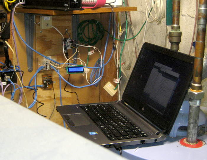 No. Easier to just schlep the laptop out there and balance it on the water heater again. Not too hard.
Loaded the new code and it worked. Replaced power with the wall wart, and I think we’re in business. After the first full day of use, it shows 10 rings and 6 NMR events. I suspect that’s correct.
Improvements!
I guess that can’t really be called scope creep, since the requirements weren’t very clear in the first place.
Final hosting
Of course more permanent hardware will be needed. A small PCB with a Tiny85 seems likely. Different voltage divider for the 2.56V ref, but that’s easy. A significant consideration is preventing the ICSP programming from failing due to those pins also being connected to something else. The relay coil is probably a killer that way, so it will go on one of the Tiny85’s precious unused pins.
It would be nice to have it report (via software serial and an opto isolator) what’s going on to the house monitor RS485 network. There’s even a node only a few feet away, so not bad to connect. But it’s another project to add the new functionality to the node.
I’ll take the cheap way out and let it talk to another Arduino with just the LCD. If I use the same wall wart, won’t even need an opto isolator. We have a plan.
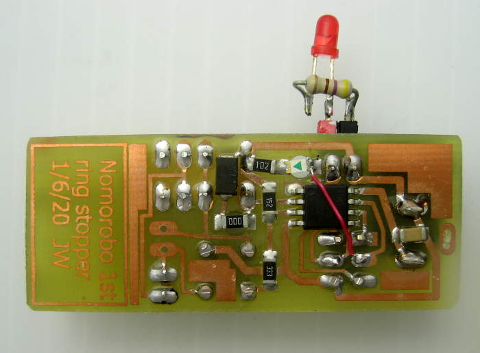
Production PCB
Around 1/6/20 I made up a PCB for a Tiny85-based ring stopper. The first error, realized after etching but even before drilling was no snubber diode for the relay. I should be able add an SMT diode if I give up the LED across the coil and use its resistor pads.
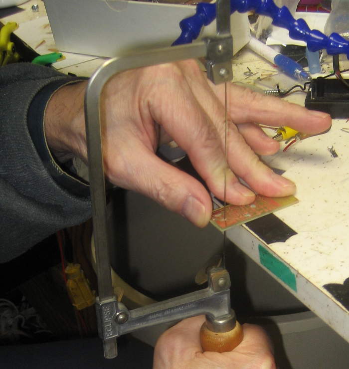 The barrel power connector had flat terminals. Used oval pads and tried drilling 3 holes for one; fail. What worked was using a jeweler’s saw and a very thin blade – just fits my standard #64 hole. Took only a little while.
 The slots are ugly, but functional. Took the blade out of the first hole maybe 4 times to check if it fit. Second hole was maybe only 2 tries. I need to remember this approach for the next time I have a flat terminal for a thru hole. (Of course hindsight says we didn’t even need that connector: could have powered it thru the ICSP header.)
Voltage divider
More tries at the math than I expected said a new voltage divider of 33K/1.5K should work. (It was close, but not quite close enough.)
 PCB
PCB
Burned Tiny85 fuse for clock not DIV8; then it worked full speed. Screwed up and chose RST pin to connect LED to, so it was on all the time. Did nice air wire fix, but to the wrong place. 🙁 Unsoldered, did better second time (to pin 7/D2/SCK). Grumpf. Relay, serial, LED all seem to work.
 Found a safe place to drill a hole for a tiny zip tie for strain relief, and added the male pigtail. I think it’s hardware complete. (Turns out, no.)
Got hardware ‘hello world’ of sequential blink LED, LED on serial port, click relay to work. Very good. Got SoftwareSerial working at 1200.
Voltage divider final tuning
Tried to verify analog reads with old HP supply connected to tip/ring in, printing analog values to serial. Learned about analogReference( INTERNAL2V56 ) vs INTERNAL2V56_NO_CAP. Oops – that supply is ground referenced. At least it doesn’t look like I hurt the chip.
Tried actual line in connected to VOIP line to get A/D values to set thresholds. Used laptop on battery with USB serial adapter. Didn’t bother with ring, as 1023 gives no info. On hook/48V-> 885 A/D counts. Off hook 175 counts. I have my thresholds.
But would it exceed max Vin on ring? 885 counts (48V) is 86.5%FS, so FS (=2.56V) means 55Vin. That’s 107 Vin for 5V at the pin – at the ragged edge. Abs max value can go to Vcc+0.5V so it should withstand 118V. Our peak is ~104V. But the headroom is uncomfortably small. Boo. But I’m going to use it anyway. (Does that mean boo me?) If I had a 1206 1.2K for the divider I’d use it, but I don’t. A quick Ebay search found nothing helpful in the US.
Hardware hack
Hmm. If I put another resistor in series with the incoming line voltage – just to the bridge, not in series with line out – I could reduce the voltage the Tiny85 sees. That bridge is looking into 34.5K. I can easily get as much headroom as I want that way. And since the A/D has way more resolution than I need for my 3 possible line states, the lower resolution isn’t a problem.
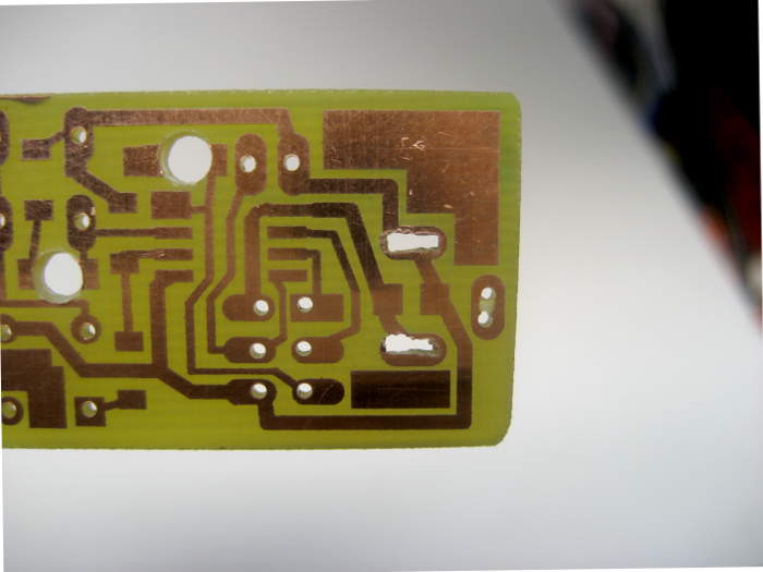
 AND – there’s a place on the board I could hack one in! One trace cut and grind out some fill. If I’m concerned about exceeding safe voltage, I have no choice. So – how much headroom do I want?
Wow – I just got an extra 6% headroom! Feels much better. Hmm – I have a 1206 39K. I could have just replaced the 33K top of the voltage divider with that and gotten more headroom, more easily. Oh Well.
Was this just my fault for not making the divider right in the first place? The math above (->33K) is correct. I guess tolerances just were the wrong way. Oh Well.
Now I need to run it up connected to the real line to verify peak voltage on the analog input pin with a ring.
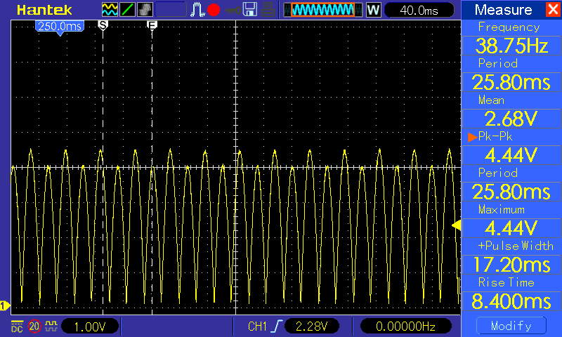 The scope reported 2.08V on-hook (fine) and got a single trace ring snapshot. The key bit is Max of 4.4V. Yay – we’re safe!
And a double check of 2.08V idle gives 2.08/2.56*1023=831 counts. Just about what the Tiny reported via serial. Great! Well, as long as I can remember not to disconnect power while it’s plugged into the line. That 2.08V on-hook is still above abs max Vin with Vcc=0.
Results
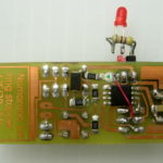
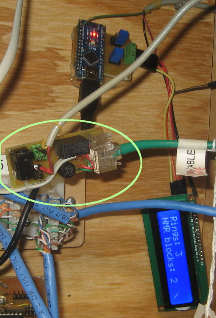 Sorry for a closing pic of the device just hanging by its wires, but until it gets a case and an opto isolated node on the monitor net to report to, this will have to do.
But it’s up and running, reporting its results, and we haven’t heard one of those NMR one-ringers in the several days since the first proto went online!
Code and board info
Inspired by a question from a reader of this post, I’ve put the code for the main controller, plus what runs the LCD up on github. In the off chance they’re useful to anyone else, the Eagle files for the PCB are there, too.
Pingback: Hardware Hack Makes Robocall Blocking Service Even Better ~ Cornay Britz
I would be interested in talking with you about this further. I am part of a team calling ourselves “ECS” for now, and we’ve been working on various technologies and solutions to stop unwanted calls. While I do have some concerns about the implementation of a DIY project like this on a POTS system due to legal reasons, there is no reason why this couldn’t become something more and FCC approved. My team and I have been playing with this idea for a while (about 3 years or so that I am aware of). We’ve even gone as far as researching and doing up the patents for something that looks very much like this. The fatal flaw of something like this however is that caller ID can be spoofed, which is why we were not putting a priority on something like this for our system yet. (However, we’ve already been working to address this flaw with our own system) We’ve taken the idea much further than call discrimination and caller ID verification and we hope to have a viable product available to the public in the not so distant future but as things go, funding is always an issue, especially for services that would be offered for free for basic usage. Perhaps some people don’t have the same vision my team does. I am the lead developer. Our websites are enhanced.tel and enhanced.biz. We have an Android & iOS app also in the works. The fatal flaw of every system we’ve seen is the use of Caller ID in all implementations. We are going way beyond caller ID verification. Seems like the device you have been working on here is very much in line with one of our projects, but we’ve got our own spin on things.
BTW, Caller ID FSK data will be visible between the first and second ring. You have around 200ms available to capture the FSK data before the second ring if I remember right. Somewhere in my research, I was able to capture FSK data while not physically connected to the POTS system but instead by simply being within close proximity to the line. Essentially skirting the requirements that the device be FCC approved for connecting up the POTS system. We have a list of design requirements for our implementation of this kind of thing though.
If any of these of interest to you, please reach out to me personally as I am the lead developer. Feel free to call me on my cell 415-THE-NERD or email me.
Hi Nicholas, how are things going with your project(s)? The websites enhanced.tel and enhanced.biz show as essentially under construction.
Jim, WOW – your “Robocall Destroyer” is terrific! I am not an electronics wizard, like yourself, but I would be the first one in line and be really excited to purchase one of your “clever” devices once you start selling them! Can’t wait!
Hi Kevin,
Glad you liked the ring stopper. No commercial plans at the moment, I’m afraid. But if I do hear of anything, I’ll certainly post about it here.
Cheers!
Jim
Interesting build. Some comments…
You said: “The device needs to be right after the VOIP controller/modem.”
In VOIP land the correct name for the “VOIP controller/modem” is VOIP ATA. ATA stands for Analog Telephone Adapter.
What you have duplicated (in-part) is the ring detect and answer supervision option found on some POTS FXS SLIC’s (Plain Old Telephone Service – Foreign Exchange Station or Subscriber – Subscriber Line Interface Card). Today SLIC’s are based on mixed-mode analog/digital SLIC integrated circuits that support the SLIC BORSCHT functions. BORSCHT stands for Battery feed, Overvoltage protection, Ringing, Supervision, Codec, (2/4-wire) Hybrid, and Testing.
https://en.wikipedia.org/wiki/Line_card
https://en.wikipedia.org/wiki/Plain_old_telephone_service
https://en.wikipedia.org/wiki/BORSCHT
https://en.wikipedia.org/wiki/Foreign_exchange_service_(telecommunications)#Foreign_exchange_office
https://en.wikipedia.org/wiki/Foreign_exchange_service_(telecommunications)#Foreign_exchange_station
https://www.3cx.com/PBX/FXS-FXO/
Studying the datasheet and/or application notes for a modern SLIC chip would probably haved saved you a lot of time and effort. Try a search for SLIC on the likes of Mouser or Digi-Key.
Hi David,
Thanks very much for your comments. I’m not a telephone guy (obviously), and appreciate the information. If I make another version (and another poster would like to discuss that), I’ll certainly look into using a SLIC chip.
But more valuably, I hope your note will remind me to do what I should have done here: Next time, step back and ask whether there are already commercial devices to do some or all of what I’m trying to do. (Especially when it’s as ubiquitous as phone stuff!)
Thanks again.
Jim
Love this, if I was using VoIP I’d have this installed immediately!
I use the Digitone Call Blocker Plus! (the old version which can be bought on Ebay) with all functions turned OFF except First Ring Suppression. I wouldn’t recommend purchasing the latest upgraded version from Digitone web site or Amazon. This is because the latest version is a badly engineered device that can’t keep up with auto-dial, causing it to drop numbers that are dialed from your phone. Digitone is aware of this but have said they are unable to fix the issue. I guess they are dependent on cheap third-party electronics that underperform. BTW this is a fairly common issue with lots of electronics today, use of poorly designed third party electronics that hardly works but is cheap. Profits before functionality, I always say! Shareholder value first!
I didn’t know there were others that could do this! Thanks for the reference!
Hi John, could you provide more details about “Digitone Call Blocker Plus! (the old version which can be bought on Ebay)” — is there a manufacturer part# or model# that uniquely and clearly distinguishes the “old version” from the newer “badly engineered” version?
I am building a call blocker using Obihai. Your ideas and thought process is great. Maybe we can turn these into a product.
https://github.com/djeraseit/Call_Log
Hi THeodis!
Thanks for the comment. I didn’t know about the OBi stuff (or all the other VOIP interfaces), so I learned quite a bit! Your github project/approach looks interesting. Good luck!
Jim
Oh dear lord, Jim. I believe we are all kindred spirits in this here forum. I am from WV…very rural(40 from a grocery, 20 minutes from a fuel station). Have no other providers in my area that offer reliable phone other than the dreaded Frontier…good people terrible service.
Anyway a rather long story short. I am approaching this from a slightly different angle. We do not have VoIP we have “digital voice” which at this point I am not really sure what that means. All I know is that Frontier VOIP customers have access to a call management software free as part of the deal that is essentially able to monitor and block or whitelist numbers at the click of a button(I have never actually used it since it is not available)…but I fell in love with the idea of implementing something like that here. NOMOROBO will not work apparently for much the same reason. I tried. BUT a dude over on github created a fabulous Raspberry Pi thing called Call Attendant. AND it works perfect, except I am left with wanting to mute this darn first ring. I see the “ring supressor” but it specifically states it is not for POTS or ADSL lines…which I believe is what I am running on. What I specifically want is a device or option to mute this first ring…I am an electronics engineer at an iot company but this is currently over my head. I was wondering if you had any ideas that you could throw at me? It would be great to get a good first step going.
Thanks in advance,
WD from WV
If I’m looking at the same thing, emxsys Call Attendant looks like it does almost exactly what Nomoorbo does.
Not sure what ‘ring suppressor’ you’re looking at, but if it says not for POTS, I agree it probably wouldn’t work for you.
I think what I put together would silence that first ring for you. Sorry to say I have no commercial plans for it. But if you can find a kindred spirit electronics guy at work who’s similarly annoyed by that first ring, maybe you could get him to replicate mine, and make a second one for you!
Good luck!
Jim