
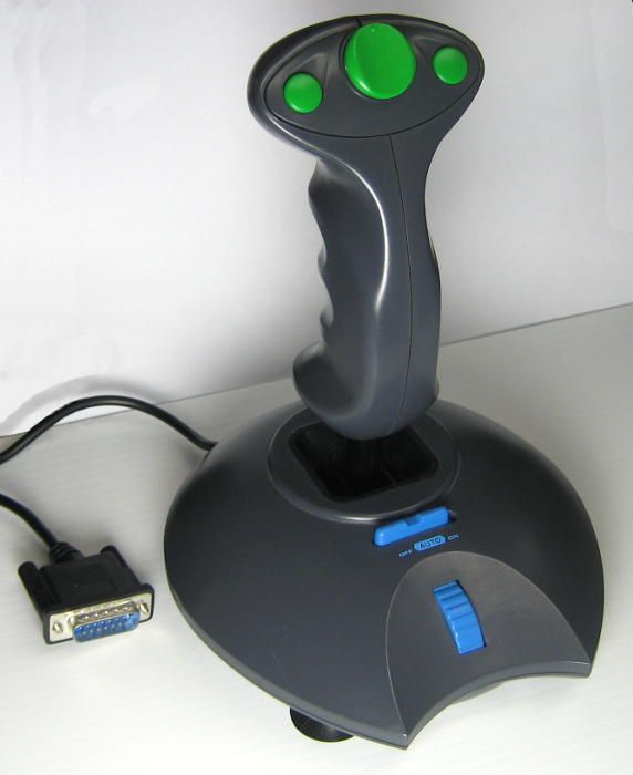
 I found this nice-feeling joystick for $2 at Goodwill, and thought it might make a good controller for an early demo of the LED wall display at the Northside Mini Maker Faire. I’d originally planned to use a drum pad, but this is probably better.
As a non-gamer, I had no idea what the interface to this thing was, and it had absolutely no brand/model info. But the discovery/learning process went well. Googling “image pinout 15 pin joystick” got me well 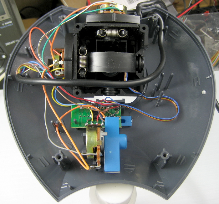 on the way. An ohmmeter showed analog resistance changes on the X and Y pins, though the buttons were a little strange. Opening it up let me ring out the cable and see what was going on. Seems nicely made. Joysticks were 100K pots to +5 wired as variable resistors. All the buttons went thru a little PCB that got +5 and ground and was mounted to the “Auto” switch. Seems to provide ~6Hz square wave auto firing on the trigger and big buttons (not on other 2). Here’s the detail:
DB-15 Joystick    function     DB-15 to      Arduino
pin   cable color              Arduino color pin
1     Whi/blk    +5V           Red           +5
2     Blu        Btn 1 (trig)  Ora           A5
3     Grn        X1            Whi           A4
4     Brn        Btn ground    Blk           Ground
5     -
6     Ora        Y1            Brn           A2
7     Blk        Btn 2 (big)   Blu           A1
8     -
9     -
10    Red        Btn 3 (left)  Whi           A3
11    -
12    -
13    Gray       Speed         Grn           A0
14    Yel        Btn 4 (right) Grn           A0
15    -
Arduino interface
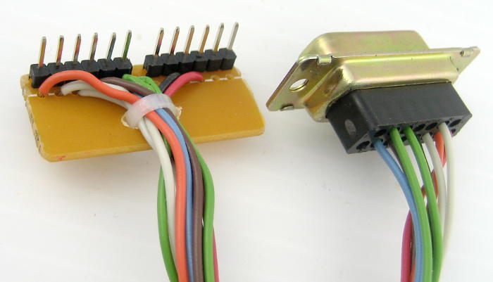 I found an old DB-15 female in the junk box and moved a couple of wires around to get red/black for power and populate the other needed pins.
The pots give ~65K to +5 when centered. To get a reasonable analog voltage from them, I made a voltage divider from their pins to ground with 43K. Seems OK.
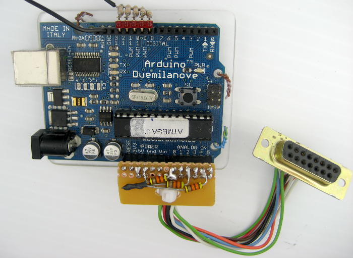 I needed 3 analog inputs plus 4 digital inputs for the buttons, and +5/ground. I could almost get away using just the Arduino header row with A0-A5 and +5/ground, and that neat connection was very appealing. So I cheated: I tied one button (right) and the “speed” pot both to A0. To read the button, do an analog read and check for near 0. To read the pot, if the analog value is very low, ignore it. I wrote a little test code and it seems to work OK.
Overall, it was a pleasant little adventure, and for $2 (plus some time) I got a useful controller for the LED display demo that will probably also be a useful input device for some future Arduino projects.
 And a big plus: It lets me get the large, clunker Harmonix USB drum pad I dug out of the spider hole at the space out of the house and back to the hole! That earlier intended wall display controller does in fact work (well, the 3/4 of it that’s still there), as demonstrated by the older, free Drum Machine windows app from Andrew Rudson. But the joystick provides what I need with not only less work but with a smaller volume of junk in the house – and that’s a win!
Nice hack. We used similar analog joysticks back in my C64 days. The pots tend to get noisy after a while.