Background
The damn NVG589 modem on my ATT Uverse internet/phone service failed again today 12/5/15. This post will be a place to keep details of this and subsequent failures. There have been many in the past; I’m sure there will be more.
Update: This now contains history of the Comcast/Xfinity Arris TG1682G cable modem installed 7/26/19. Those details start here.
I put router reset stuff into the home automation system years ago (4/11) to protect against router/modem lockups making the home monitoring system unavailable when we were out of town. The local server pings our ISP’s first router, and if those pings fail for a while, it tried to reset the modem and router (then separate devices) by cycling AC power to them. It took a couple of rounds of rewrites before timing issues causing infinite reset loops were ironed out (oops), but it finally got pretty robust, and automagically kept our internet connection up when we didn’t even know there was a problem. Reset events are posted on the main HA page.
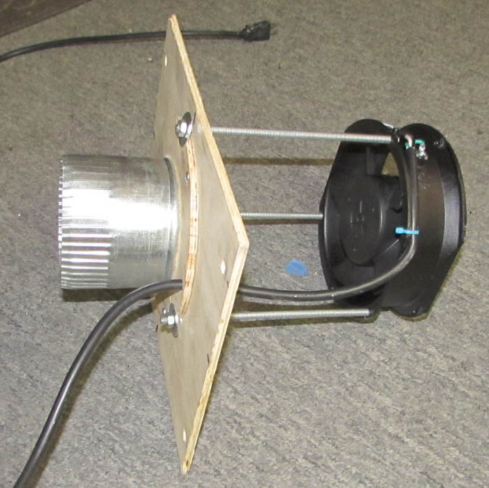
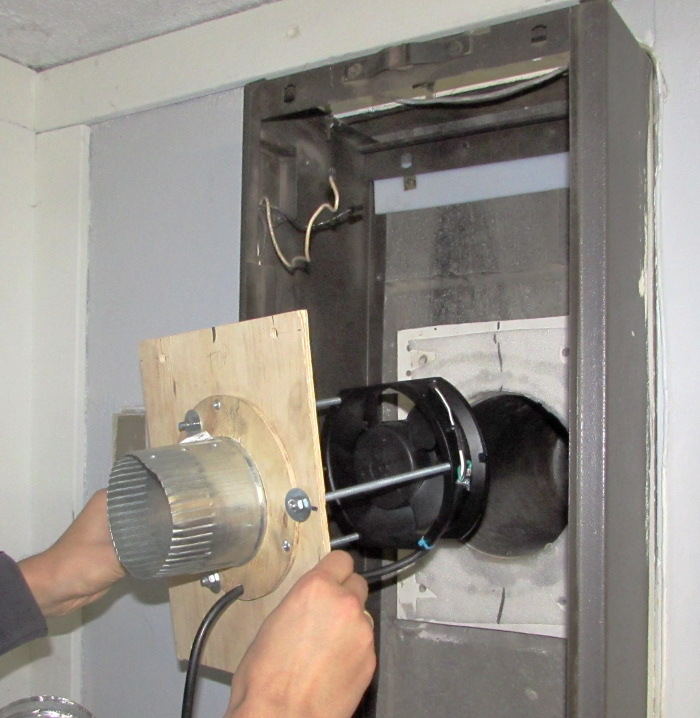
When we switched to Uverse VOIP (when? a year or so ago?), AT&T swapped our old modem for an NVG589 (and started charging us $7/month for it!). That device has internal battery backup (most appropriately for a phone connection), so my dear old power cycling would no longer work, and so I disabled it. The modem runs off my local UPS, so removing the battery wouldn’t be a show stopper (and would let power cycling work again!), but somehow I haven’t been quite willing to do that. I investigated rebooting the modem programmatically, but at least partly due to a password dialog, I gave up. Now I no longer have automated reboot capabilities. I’ve considered a solenoid striker strapped to the back of the 589 to hit the reset button, but have done no work to implement it. (A servo might be a practical, lower power solution.) After the latest failure, just removing the battery is looking better and better.
The 589 was replaced a few months after we started with Uverse, basically for the same kind of failure, and I think a guy came out one time since then for similar failures, but didn’t replace it again. There was also a very unpleasant incident with AT&T support where they remotely did a factory reset of the modem when they said they were going to reboot it. That wiped out all my network customizations, Wi-fi SSID and passwords, etc, made me a very unhappy customer, and caused a lot of extra work to get my network back up as it was. I had them put a note in the account file to NEVER do that without expressly asking me. I’d like to back up the config, but several investigations have all pointed to the fact that there is no way to back the config up except looking at the screens and writing everything down! (OK, could take screen captures.) That really sucks, Motorola/Arris.
It looks like rebooting the modem also wipes the logs. I learned that after the reset button reboot today when I tried to go into the logs to see when it first detected a problem. I hope I remember to grab the logs before I reboot it next time.
Current status
(last updated 7/2/16, 7/27/16) We’re on about the 5th modem now, a Pace 5268. My ping/power cycle stuff is back in place and seems to be working. Had a bad case 7/27/16 of a reset loop which might have been my fault. Increased time between resets to 700 sec, but have no info if that’s appropriate.
Failure event details
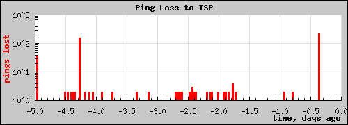
(first) Event: 12/5/15 As has happened 3 or 4 times previously, both Internet and phone were out, with the modem showing green on both Broadband lines, green on Service (!) and off for phone line 1. My watchdog noted old file on the host at ~7:30 AM. We noticed internet out about 10 AM. The ping stats display on the home page showed ~1000 missed pings. I showed Laur how to reset the modem, but since it’s hard to get to, that wasn’t pleasant. I need to add bookmarks to browsers on all the devices to check modem status.
I called AT&T service (after it was back up) and complained that the modem knew at least that the phone was out, but didn’t fix itself. The rep (Cara) seemed puzzled that both broadband lights had been green as well as the service light, but internet had been out. She did a remote reboot, and after the usual 15 or 20 minutes it came back up and internet and phone were good (again). She scheduled a service call for Monday AM. She also told me that the My ATT phone app would allow remote rebooting. Cool. I just set that up on Laur’s phone as well as mine. Actually, that reduces the pressure for an auto-restart facility driven by fearing failures while we’re out of town. Of course we’d still like it to fix itself even when we are at home. (Doesn’t actually work: see update 1/18/16.)
While I was still on the phone with her, the modem spontaneously restarted. She offered to wait ’til it was up again, but I said I was pretty confident it would be OK, and I’d call again if it wasn’t. Sure enough, maybe 20 minutes later all was working, and seems to have been OK since. My watchdog noticed the second outage, and again said the datafile on the hosting server was > 1260 seconds old. I wonder if I can get that watchdog to send me a text on failures.
Update 12/6/17: AT&T guy came as scheduled. Did several tests inside and outside with a tester that plugged into my bonded VDSL pairs, saw it sync WAY faster them my modem ever did. He replaced a couple of connectors and the last cable to the modem, but his tester sync’d in less than a minute at the end of the same cable that my 589 took many minutes to sync on. While the modem does usually take a little longer than the tester, the difference was more than he would accept.
He replaced the 589 with a brand new one – same slow sync behavior. Then he replaced that with a new NVG599. That’s bigger, faster, supports high end service. That sync’d up quicker, and that’s what he left in place. Of course I had to reconfigure it with my local network and wifi details, but at least I’d cleverly gotten screen snaps of those bits of config before he came. 🙂 Unfortunately, just like the 589, the 599 has no way to save config info to a file.
Interestingly, my all-but-static IP address changed with the new modem. The little wget-based screen scraper that runs in a cron job to read the gateway’s /cgi-bin/dslstatistics.ha page and emails me if the IP address changes no longer looked for the right hard-coded strings, so I had to touch that up. While the main PC has a fixed address allocated by the DHCP server, and stayed on my non-standard subnet, the nice red laptop in the kitchen runs a normal DHCP client, and so by pulling and replugging its network cable could see the gateway on its default 192.168.1.254 address and let me do the initial config without having to drag a laptop down to the basement and wrassle cables. Much more civilized.
I continue to consider pulling the battery on the 599, but continue to hold off. The home monitor page reports occasional “router resets” – presumably meaning it missed more than 20 consecutive pings (pings every 5 sec). But the ping stats graph doesn’t show any missed pings. I should look into that. But especially with those not consistent, it’s hard to pull that battery.
(a few hours later) OK, there’s one bogus reset reported 12/8/15 06:47. I can’t find any evidence of missed pings near that time. There are a whole bunch of resets mid 12/7, but there’s a big bunch of missed pings at that time as well, so those match up.
Ohhhh… When I was trying to figure out how the reset stuff had been turned off, I’m medium sure I touched a file (presumably “resetFlag”) to see if it got picked up by the main poll program. (It did.) Pingstat.pl writes its ping info (including the critical “got reponse after N…” entries) to pingstats.csv, from which the ping stats graph is made (by graphs.php). But completely separately, when it thinks there should be a reset (power cycle) it touches resetFlag. The main poll program – which of course is the only thing that can talk to the 485 modules – like the power cycle controller – looks for that flag file to know when to send a reset message. The resets reported on the main monitor page come from the main poll program’s datafile.csv – essentially independent of the actual ping stats, linked only by the reliability of pingstat.pl. I broke that reliability by experimentally touching the flag file. So that bogus reset report was truly bogus, created by me trying to figure out how stuff worked. So it can safely be ignored.
That removes the concern about flaky false positive reset requests – yay! I’m still not going to run right over and pull the battery out of the 599, but at least I have confidence (once again) in the reset detection stuff. And I recorded it all here so maybe I won’t break stuff the next time I need to know how it works. 🙂
Update 1/18/16: Discovered that Internet and phone were out again this morning. The good news is that the NVG599 knew about it and was working on it. Unlike the 589, the status page showed broadband and phone down, and from the lights on the front it was clearly trying to resync. The bad news is that after 15 minutes or so, it was still failing.
I thought it would be a great opportunity to test out the remote restart capability the rep told me about in the My AT&T app on my phone. Found the app, logged in, found the U-verse restart screen. There were 2 choices: Automatic and Manual. Since I wanted to test doing it when we’re on vacation, I chose Automatic. Click, whirr – and an error message came up to the effect that this service is not available at this time. Apparently you can only restart the services when they’re already working. That’s dumb, AT&T.
Went downstairs and hit the reset button. In a few minutes, we were back on the air.
Ping stats showed about 350 missed pings (in 2 or 3 batches), for about 29 minutes of outage. The reset algorithm logged 10 tries to restart between 10:38 and 11:14AM. Of course that doesn’t actually do anything right now, but re-enabling it and pulling the 599’s battery is looking better and better.
Update 4/5/16: Service went out again last night. Phone and internet were out suddenly. From router web interface tried to restart phone line, got something like “verification error”. Tried to restart broadband, somehow failed. Restarted device (still from web interface). Eventually got both broadband lights green, service red. Waited a few minutes, gave up and hit red button on back. It rebooted, came back to both broadband LEDs green, service red. Waited more minutes – no change. Called AT&T (from cell). They said they were going to run some tests. Service came back while on the phone – don’t know if it was something they did. Also don’t know if it just took a long time and would have eventually come back after the web interface restart.
Rep (Andrew) said it looked like cabling from NID to modem, and they would send someone out. HA showed ~120 lost pings, 9 “resets” over 38 minutes.
Colin came out today (Tues 4/5) (again tried to go to Villa Park instead of Elmhurst). We talked, but apparently miscommunicated, and he reset modem to Factory, fucking my whole network! He said something about multiple IP addresses but wasn’t clear. I said I thought I was clear to do whatever I wanted on my side of the modem. He replied something like “Well, mostly.” Couldn’t pin him down on what I couldn’t do. What I eventually got out of him was that anything non-stock (changing wi-fi, local subnet, DHCP allocations, etc) increased the risk of something going wrong, for example when an update came down. He said the problems seemed to start Apr 1. I asked if an update had been sent down and he replied quickly that he couldn’t tell anything like that. Nice.
His resets showed up as another 120 missed pings, for 37 minutes of 10 “resets”.
I asked about the MyAtt app only being able to restart service if it was already working. He said if at least some broadband lights were green – like flashing trying to sync – they could talk to the modem enough to restart it. Don’t know if I believe that.
Took advantage of the factory reset to refine my notes on what needs to be done to get back after such a reset. Again used red Gateway to get into modem on default 192.168.1 net. Had to pull the cable to get new IP. Did ipconfig/renew on main PC to refresh its IP. It got its same IP back, and then I was able to tell the modem’s DHCP to always give that IP. Added details on enabling outside access to the Pogo. All details are in My Documents PcSetup/RouterConfig.txt.
Also couldn’t talk to the new TP-Link access point. Lights showed a problem. Power cycled it and it seems to be back on the network. Seems like I couldn’t connect to that AP (Jims G Router) for quite some time. Wonder if it’s been down for months.
I still need to call AT&T: change service addr Villa Park->Elmhurst, and ask for specific answers to when MyAtt app can restart modem.
Update 5/13/16: Got home and found internet and phone down again. Logged into modem; it said broadband was down (as well as phone). At least that was right. Tried to restart broadband, but didn’t help. Hit the red button on the back, and it was back up in a couple of minutes. Why should I have to do that? Ping stats showed 1100 missed pings. At 5 sec/ping, that’s about an hour and a half.
Called AT&T. Rep “Dawn” was friendly and responsive, but couldn’t see anything wrong. Right – it’s all working fine after I hit the reset button. I asked if she could confirm the 90 minute outage my ping stats showed, and she said they couldn’t tell anything like that (in the past). She offered to send someone out, but it didn’t seem worthwhile. She offered to monitor the line for a week, and I said to go ahead with that. My estimate was 95% probability that there would be no problems.
It looks like the problem is that the modem gets stupid and can’t recover. I don’t know how often the modem notices a problem and does reset itself. I suppose that might (better!) be shown in the logs. I think I tried to get the logs sent to the PC, but it probably didn’t work or isn’t working any more.
Hmm – I wonder if the connection between the battery and the modem is accessible. Maybe I could add another relay to the reset node and have it both power cycle and temporarily disconnect the battery. If I just pulled the battery, they might notice it and want to send someone out to fix it. Maybe that solenoid on the reset button isn’t such a bad idea. If it were AC powered, normally retracted (reset button not pushed) and spring loaded normally “pushed”, it would require no additional software changes.
Maybe I should have the reset stuff email me when it kicks in.
Update 6/19/16: Damn modem locked up again – this time while we were away on vacation. According to the 106 “router reset attempts” it was out for about 7 hours. Hit red button when we got home and it all came up promptly – just like every other time. Called AT&T, spoke with “Sherry”. She says there’s a problem with signal to the modem and that’s why it fails. They say that most every time, but I don’t believe it. (I can believe the signal isn’t perfect, but I have trouble believing that’s why the modem locks up and can’t restart itself.) Tech will come out tomorrow morning.
Oops – the time slot I agreed to with the rep on the phone won’t work. My fault. I logged into My AT&T phone app and was able to change the appointment time with no problem. Gold star for AT&T for providing a simple, effective tool for at least that application. Too bad it can’t restart my hung modem, but they do get credit for what does work.
That outage was the straw that broke the camel’s back: I’m going to re-implement my router reset stuff. Found a schematic for the resettable power outlet, and it looks like the PIC node puts out 5V to operate a relay. I should be able to use that to hit the reset button. Looking around for a solenoid I can bolt to the back of the 599 to hit the red button…
Update next day 6/20: Service guy came (to Elmhurst instead of Villa Park – progress!) and swapped the NVG599 out for a Pace 5268AC. Took quite a while to sync, download an update (power LED blinking yellow), install, restart. He said the 5268 was a more stable modem. We’ll see. Reconfigured the new gateway with my network stuff, updated Jim/Documents/PC Setup/RouterConfig.txt. Got new IP address. The user interface on the new modem is completely different, so in addition to slowing me down in setting up the config, it breaks the monthly ‘warm fuzzy IP check’ script (perl/checkip.pl). I made a quick first try at patching it, but failed. Just need a little more time. Update: Fixed.
Set up a syslog 1.2.3 server from Sourceforge on the (now Win10) machine to capture the logs. Seems to function, but won’t log much. Status bar shows messages coming in, but nothing sticks. Still noob playing with it.
We’ll see whether the new modem locks up the same way the 599 did. This one didn’t come with a battery (though there’s a place for one). Guess instead of mechanically pushing the reset button I’ll just hack the timeouts in the existing ping test stuff and enable it so it actually power cycles the new modem.
Update 6/21/16: Touched up pingstat.pl to 30 consecutive missed (5 sec) pings to declare time to restart modem, and dead time between restarts to 500 sec to give the gateway a good chance to resync. Restarted pingstat.pl. Ensured only modem was plugged into controlled outlet, and reconnected the outlet control line to the reset PIC node. I’d cleverly put a well-labelled dummy connector on the same pins and in the same orientation as the wire to the controlled outlet, so reconnecting was trivial. I think it’s all in place and armed. I think.
Update next day 6/22/16: Touched resetFlag, and sure enough it power cycled the modem! Broadband lights came on (red) after about 4:30; Service went solid green after about 6:40, with phone up several seconds later. Since I triggered the reset artificially, the dead time between resets wasn’t in force yet, so I think it detected ping loss while the modem was restarting, and power cycled it again. Main HA page showed 2 resets – again because of touching resetFlag plus one normal ping loss detect plus power cycle. Hooray for having written up how that works above! All is good.
Update 7/1/16: The new 5268 apparently failed today. The good news is that the restart stuff kicked in, power cycled it, and it all came back up automagically. I was on the computer when it went down, and was inconvenienced for a little while, but other than going downstairs and noticing the lights on the 5268 were in a restart pattern and picking up the phone during and after the reset to check, I did nothing to help the process along. I haven’t decided whether to call AT&T about it.
The syslog server seems to work, but doesn’t start or save the filtered log data automatically, so I don’t have the logs from the most recent reboot.
The main HA page showed one reset (07/01 20:34:02) and about 160 missed pings. So as near as I can tell, everything (except log capture) worked perfectly. Yay!
Update 7/7/16: Another fully automatic reset. Didn’t even know about it – it just worked. Main HA page showed about 130 missed pings. At 5 sec/ping and a count of 30, I’d expect more like 150. But the missed ping spike was still completely clear, and I’m confident the reset was justified. I suppose the question of whether the modem might have taken care of it by itself remains. Guess I need to get the logging stable to see if I can infer anything from that.
Update 7/27/16: Another auto reset yesterday 7/26. I sort of quit even logging them here because it just works! Well, not quite. Log on home page currently looks like this:
0 07/26 15:21:43
1 07/27 09:09:24
2 07/27 12:03:30
3 07/27 12:11:54
4 07/27 12:20:18
5 07/27 12:28:42
6 07/27 12:37:05
7 07/27 12:46:32
8 07/27 13:08:34
9 07/27 13:10:40
10 07/27 13:18:01
11 07/27 13:19:05
12 07/27 13:27:28
13 07/27 13:28:32
14 07/27 13:35:53
15 07/27 13:37:59
I noticed the phone said “No Line” today 7/27/16; RG was in the process of resetting. Fine. Checked back in a few minutes – still down. Started poking around on the Pogo, and it looked like it might be in a pingstat-initiated reboot loop. Unfortunately, all the “Resetting router” timestamps in pingstatstdout were the same – from the very first instance.
I moved the global timestamp code in pingstat.pl to a new function and called appropriately so resets would show correct time.
But it was still looping. So I kicked the $resetTimeout minimum dead time between resets from 500 to 600 sec, waited until it resynced to restart pingstat.pl. But then the reset loop restarted!
Pingstatstdout showed continuous ping fails to ISP. Ooooohhh – did they change me to another router (so my pings will fail forever?) The IP of the AT&T router I ping is hard coded. Killed pingstat.pl. <waits…> Nope – same IPs for the RG (99.8.9.117) and its first router (99.8.8.1). Manual pings work fine. Restarted pingstat.pl. Seems to have gotten a ping response. So I don’t know whether my $resetTimeout was too small and caused the loop or their stuff was screwed up for a long time.
WTH? I’ll post more if it fails again. Kicked dead time from 600 to 700 sec several hours later to be even more conservative, though no new resets before that.
But how do I protect against the case where they change me to another AT&T router? Shouldn’t happen often, but I’ll stay down (or at least in a reset loop) until I fix it manually. I guess just killing pingstat process should stop the looping, though that would be almost impossible remotely when it’s in a reset loop. I suppose if I wanted to be really anal I could scrape the router IP from the router broadband page (http://192.168.99.99/xslt?PAGE=C_1_0), looking for the first (IPV4) instance of
<tr>
<td>Default Gateway</td>
<td>99.8.8.1</td>
</tr>
Of course I’d have to code around sometimes not being able to reach the page, and when not connected getting some kind of <none> value (or look for the much more complex Internet – Connected table entries before it). And I’d have to catch that new value during the narrow window of a reset loop after the RG is running but before I reset it again.
I suppose I could add a state to pingstat.pl and when pings fail (and after my powercycle!), scrape Internet Connected status from the RG. Then if not connected, I could forego pings ’til it came back up. And if I have that much, I guess I could scrape the AT&T router IP as well. Yeah, but getting a ping reply is even more absolute indication of success. Ugh.
Update 7/28/16: One more automatic reset I didn’t even know about until I saw it on the HA page, no drama, just as designed. 🙂 07/28 10:23:58.
Update 8/14/16: Another automatic reset I didn’t know about. Yay! 08/14 10:23:29 I sort of think there was another a week or so ago, but I didn’t think to log it.
Update 10/9/16: Wow. After an email from a watchdog timer saying the HA web site wasn’t being updated, I checked and found the router reset robot had fired 4 times while we were out:
0 10/09 16:40:22
1 10/09 16:52:58
2 10/09 17:04:30
3 10/09 17:16:03
Everything was running fine again when I checked it at around 7 PM. I don’t know what to do. I could call AT&T, but all they’d do is come out – interrupting my day – find that it was working fine, do some tests, maybe swap out the modem again. And it would still be running fine when they left, except I’d have to reconfigure my network back to the way it was. How does that help anything? Thankfully, it only happens once a month or so. Nuisance.
Update 10/21/16: This one wasn’t AT&T’s fault! My 9 year old D-Link 1108 8 port 10/100 switch died. First symptom was no internet, so despite a working in-progress phone call (sorry, Lauren and Cathy!) and the unusual indication from the main PC that the network cable was unplugged on and off, I power cycled the router. (Manually, of course – since I couldn’t even log into the Pogo to have it do it via the sendusr1 interface to 485pollC.pl. Ordered a new switch from Frys.
Update 10/26/16: More failures cheerfully and invisibly fixed by the auto power cycler.
0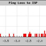 10/21 20:22:21
1 10/22 12:49:14
2 10/22 13:00:47
3 10/26 10:23:18
4 10/26 10:34:50
5 10/26 10:46:23
The first one was from the post above – not their fault. Presumably the other 5 were legit fixes. The ping stats show the traditional signature of the outages today and 4 days ago. All I can say is that AT&T ought to be paying me for the service calls I’m saving them! I should call and ask/force them to make notes in my account record of the failures.
Update 3/18/17: There was also an hour-long series of outages that resulted in kicking up the “dead time” after a restart that it waits before declaring another outage from 700 to 800 seconds. I suspect the line wasn’t coming back in time, triggering another restart. Disconnecting the power cycle stuff and doing a manual button press brought it back.
While 700 sec had been OK before, at least some times it takes more than 700 sec for the modem to get back on line after a power cycle.
Update 3/27/17: The automagic router restarter worked on this presumed outage:
0 03/27 10:22:45
I think there have been a couple of others since the previous updates (not since 3/18). Pretty much it just takes care of itself, just as designed. Yay!
Update 4/20/17: The modem has failed a few more times – and quite a few recently. It has recovered each time without manual intervention. That’s good. Looks like there were ping loss spikes that probably line up with the resets. That’s good, too.
0 04/17 04:45:31
1 04/17 08:08:58
2 04/18 08:00:30
3 04/19 06:39:43
4 04/19 06:52:18
5 04/19 23:12:52

Update ~4/24/17: Lost internet and phone, but it was completely my fault. (Well, at least not AT&T’s fault.) The system thumb drive on the PogoPlug home automation system failed (maybe 4/20/17?) and I got it back up using an ancient backup. I’d just run that up and immediately made an important phone call (Fidelity guy) when the phone went dead a minute or two into the call. I finished the call on my cell (confirming that no longer having a real landline – but rather one dependent on the internet connection – wasn’t as critical as it once was), but noticed immediately that the modem was resetting.
When I got off the call several tens of minutes later, the modem was still rebooting – apparently in a loop – so I unplugged the router resetter node. Then the light slowly came on: That old image didn’t even know the current ISP first router to ping – so pings failed and it tried to reset the modem. Add to that that since the early version of the pingstat tool I’d had to bump up the “dead time” between resets – because it takes so long for it to come up – from 240 to 800 seconds. I was doomed to a reset loop. The resetter remained disconnected for several days, but it’s back. I hope it works again.
Update 9/14/17: I was just listening to Pandora, and all of a sudden the music stopped. The Win10 machine showed a yellow triangle/exclamation point over the network icon, but interestingly the phone had a dial tone. I logged into the router and it said “connected”. Liar. This should resolve itself.
A little later, perl/pingstatstdout on the Pogo showed 2 router reset attempts. At various points I could ping 8.8.4.4 by IP, but not google.com. I considered disconnecting the router resetter just in case it was trying too soon to reset again, but decided to let it do its thing. I also considered adding a check either to pingstat.pl or the main 485pollD.pl to check for the existence of a file called, say, NoReset, upon finding which it would not honor the request for a router power cycle. That way I could give it some more time without climbing over stuff to get to the resetter node. Looks like either would work, but not sure if I’d end up with a whole mess of log messages about it, or worse – mess up logic that assumed the reset was done. Maybe a good way to implement that would be a script that created the file, slept for say 10 minutes (or a command line param?) then removed the file to avoid defeating future, valid resets. Maybe someday.
Anyway, it eventually fixed itself on the third try:
0 09/14 14:31:44
1 09/14 14:44:19
2 09/14 14:57:58
On the plus side, it’s been quite a while since the internet connection failed. Either that or the system I put in place to fix it when it happens works so cleanly and invisibly that I never noticed. 🙂
Update 9/25/17: Just noticed another nice, invisible reset that fixed things I didn’t even know were broken:
0 09/23 06:28:53
I think this reset system is one of the best things I’ve made. And AT&T should be paying me for the service calls it saves them. 🙂
Update 11/6/17: Another one automatically fixed by my resetter.
0 11/06 12:58:25
Update 5/29/18: Another automatic reset:
0 05/30 00:44:12
Update 6/28/18: Hmm – found new failure mode. Modem said DSL and internet connections were up; admitted phone was down. Didn’t reset. Clicked Restart on phone – nothing. Both Broadband LEDs and Service were green; phone was red. Pogo could ping “isp” (99.8.8.1), but neither google.com nor 8.8.4.4. PCs etc of course couldn’t access internet (and main PC showed yellow triangle with exclamation).
The real problem was that pingstat thought it was OK, since it could ping “isp”. What do I have to ping to be sure it’s all up?
I touched perl/resetFlag, and lost connection to pogo (since apparently the connection from the main PC was thru the router). Several minutes later, modem showed power, but not even flashing broadband LEDs. Clearly the pogo had power cycled it – and power was back on. But it wasn’t coming up. Another couple of minutes and both broadband LEDs were solid green, but Service flashing. Can’t ping. No phone.
OK – unplugged wire from HA node to controlled modem power outlet to avoid any possible reboot loops. It’s been a while – but I didn’t check time. OK – 1:16A now. Now 2 broadband solid, NO Service.
Called ATT from cell, talked to robot. Robot “ran some tests”; magically it came back up a couple of minutes later while I was still on hold. Waited on hold 45 minutes to talk to a human; gave up (since it had been working all the while). HA home page showed 4 resets, so a reset loop was possible. But I think it was just calling AT&T that fixed it. I really think that’s a very important tool for the arsenal: Just call the robot, tell it you’ve power cycled the modem, let them “run some tests” and it’s magically fixed. Not worth having them come out. Now that I have a fairly new modem, I expect this approach will work.
0 06/28 00:48:40
1 06/28 00:54:58
2 06/28 01:07:33
3 06/28 01:21:12
I’d really like a camera on the modem so these sessions would involve fewer trips to the basement. I found one like the most recent one – 2MP, wifi, but has an RJ45 on the back – for $21/free. But I’m not sure how it would work: I need color to tell LED colors, but if no light is on, I think it goes to B/W. And I don’t want a real light on. I wonder if I could spoof it with some white LEDs flanking the modem. I suppose I should experiment with the one I have pointed at the electronics bench, but I don’t seem to want to mess with it. Hmpf. But I guess it’s not quite at the top of the list anyway.
Update 7/24/18: Another automatic fix that I didn’t even know about until I saw it on the web page. Go robot!
0 07/24 11:20:26
Final AT&T update 8/12/19: No more AT&T resets – because we switched to Xfinity. Cable modem installed 7/26/19.
First Xfinity failure 8/8/19: Well that didn’t take long. Xfinity router was out for an hour or so around midnight. I called, and they said they were doing maintenance and that it would be back by 6AM. Fortunately it was sooner than that. I don’t remember ever having an outage blamed on maintenance by AT&T.
The annoying/scary part was that the Google Home Minis couldn’t reconnect, announcing something like “Can’t connect to network. Check settings in Google Home app.” I eventually disabled both 2.4G and 5G wifi, saved changes, then reenabled them (and saved again). I think I had to then ‘set up’ all 3 devices in the Home app. In a subsequent phone call with Xfinity support, the rep said she’d seen the same thing.
0 08/08 00:49:37
1 08/08 01:09:41
The living room mini reported the same thing 8/13, tho the others remained connected. Guess we’ll have to keep an eye on that.
Outside cable upgrade 8/19/19: This was a planned outage. I called Xfinity to come out to get rid of the big white Comcast demarc box on the west side of the house near the front where the cable comes diagonally across the yard. (Sorry for no pic.) When I agreed to keep the cable routed there (since the age-old one was there and there was cable along the front of the house and going thru the wall near the front door), I didn’t know about the new box. Lauren saw it instantly as a blight on the house. There was nothing in the box but a lightning arrestor coupling. I was going to remove the box and tuck the coupling behind the downspout, but didn’t quite want to do that without Comcast’s OK.
The lying salesman who got us to switch, Zack Zlatko Petroski (who lied about free mobile service, lied that I could bring by old Galaxy S7 over and stopped returning my calls and emails after he failed to get the box taken care of), said he’d get it removed. When he never got that to happen, I called and arranged for a “pro install” for $70 and planned to have the cable restrung to the back corner, around the back of the house, and thru a new to-be-drilled hole behind the garage corral. (Since the guy didn’t have to come into the house, it would have qualified as a free repair service. Oh well.)
When the guy got here, he said he could do that, or bring it down and have it buried along the new fence the neighbors put up. But there were already 2 cables strung to that corner of the house, so one fewer didn’t seem like it would provide much cosmetic improvement. But one of those was the AT&T wire, which isn’t our phone any more, and could be removed. Whoa! Or, he said, he could just remove the box and tuck the connector behind the downspout, as I’d originally planned. We did that. The 8:30 outage was that process. The 6PM outage was me removing the bulky connector, cutting it down so it would fit behind the downspout better, and reconnecting it.
Note that the resetting isn’t connected yet. Not sure when I’ll do that.
0 08/19/19 08:30:45
1 08/19/19 18:00:26
Update 10/30/19: Well, the router resetter is now live. Router went out for a few hours and couldn’t fix itself. Phone still worked. This is the classic failure. Let’s see how the resetter handles it. Entries below are the not-yet-connected resetter trying desperately to fix it.
0 10/29/19 08:23:22
1 10/29/19 08:43:26
2 10/29/19 09:03:29
3 10/29/19 09:23:33
4 10/29/19 10:50:06
5 10/29/19 11:10:10
6 10/29/19 11:30:14
7 10/29/19 11:50:17
8 10/29/19 12:10:21
Update 3/18/20: Xfinity had an outage yesterday, and the router resetter did its best. I’m pretty sure there was another instance – probably a local router problem rather than an outage – that the resetter fixed for me before I noticed it. No record kept here – oops.
0 03/17/20 11:36:39
1 03/17/20 11:56:56
2 03/17/20 12:17:13
3 03/17/20 12:37:31
4 03/17/20 13:19:09
Update 4/14/20: Xfinity did maintenance, and we were dark for an hour. The phone app knew about it and reported (conservative) ETA for back up. Between them and my resetter, it came up without problems. Maybe this doc will give some view into how often they do maintenance.
Ping outage 4/14 04:00 57 mins
0 04/14/20 03:09:38
1 04/14/20 03:29:56
2 04/14/20 03:49:09
Update 4/23/20: Another Xfinity outage. Phone app knew about it.
Ping outage 4/23 09:41 121 mins
0 04/23/20 07:46:34
1 04/23/20 08:06:53
2 04/23/20 08:27:11
3 04/23/20 08:46:24
4 04/23/20 09:06:42
5 04/23/20 09:27:01

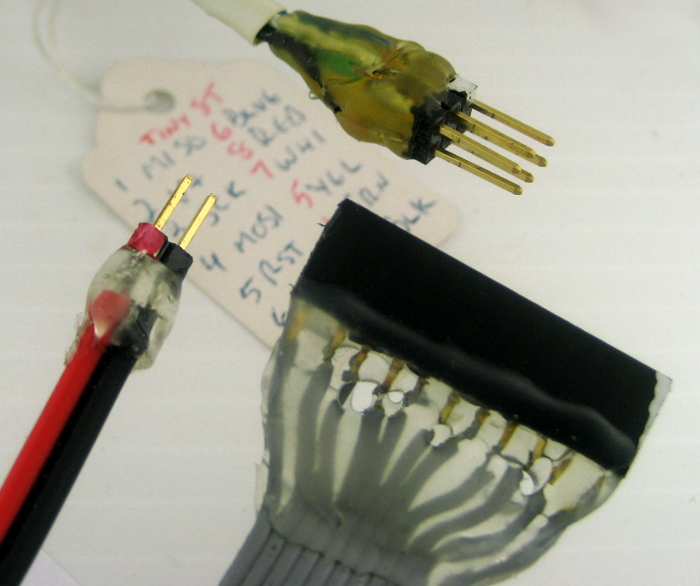
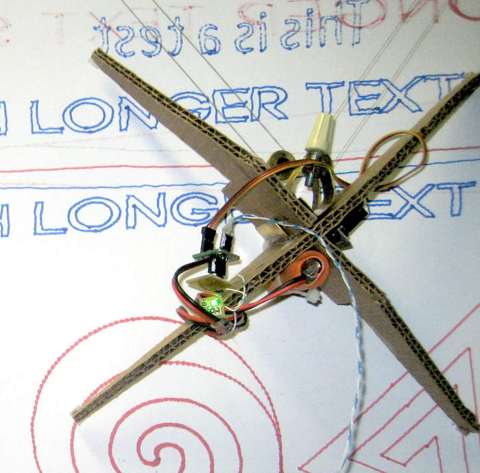 The first version of the pen lift for the Drawbot included a nice servo mechanism driven by a Tiny85, but time forced the major ugliness of a light pair of wires from the main Arduino to carry control info to the gondola. It worked fine, but those wires were never supposed to be there. IR communication was the plan.
 Finally, using a (20 year?) old 3 pin 38KHz IR receiver still in its Radio Shack bubble pack, I made up a PCB
 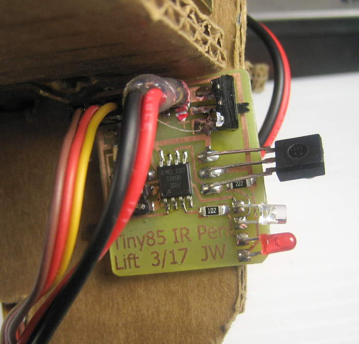 with a Tiny85 listening to the receiver module, driving the servo to lift the gondola and red and green status LEDs (for pen down/up). I defined a simple pulse position protocol (in DrawbotStuff/DrawbotTinyServo4_IR.ino) on top of the required 38KHz pulses to deliver the 1 bit (up/down) messages, made up a test sender with an Arduino and an IR LED sending alternate state messages every half second and got it working.
 A little aluminum bracket glued to the back of the PCB clips it to the gondola. Servo and power wires were both perfect length to go to the board. Sometimes we just get lucky. 🙂
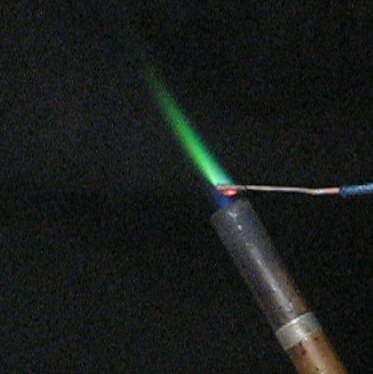
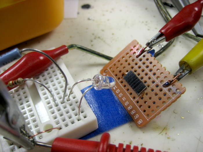 Christine suggested maybe the LED output was nonlinear and at the lower current wasn’t putting out as much as expected. I tested with a very small 8 cell Si solar panel directly into my bench meter in current mode (~100 ohms),
  which I think is a good way to test for light energy in. (I crudely covered the panel to keep out ambient light.) Results of output current v LED drive current were VERY linear, 1-30 mA. So I think doubling the current does indeed double the light output.
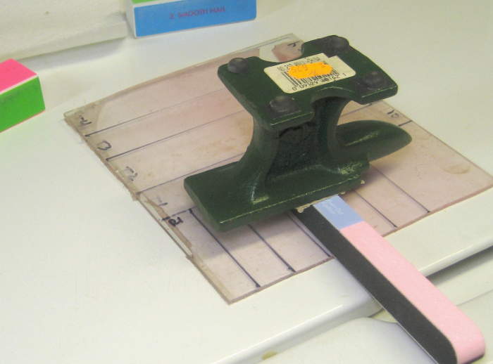
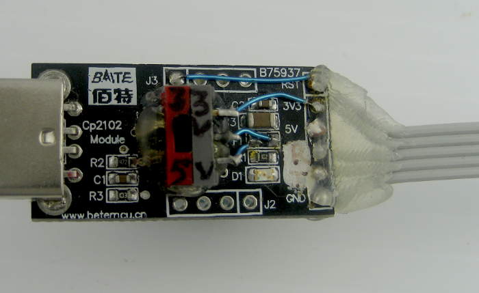
 To provide known current pulses, I set the IR LED up with a fixed resistor and an adjustable bench power supply. Pulse current was gated by a logic level MOSFET driven by an Arduino (or sometimes a bench pulse generator).
 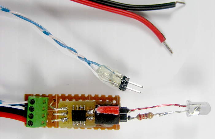 I mounted the FDS6670 MOSFET (in its odd SOIC 8 package) with power, logic in, and load connections so it might be reused some time.
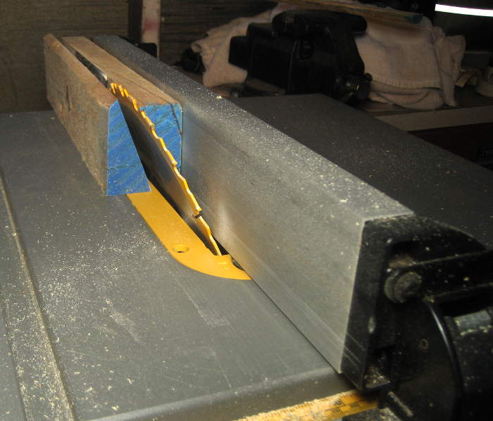
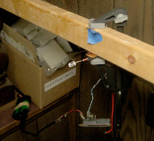 Knowing I’d need a long straight shot, I mounted the LED (with
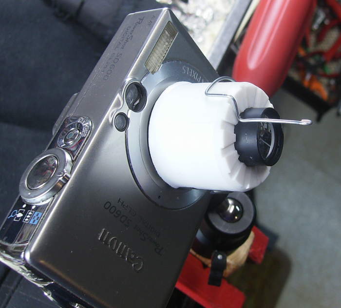
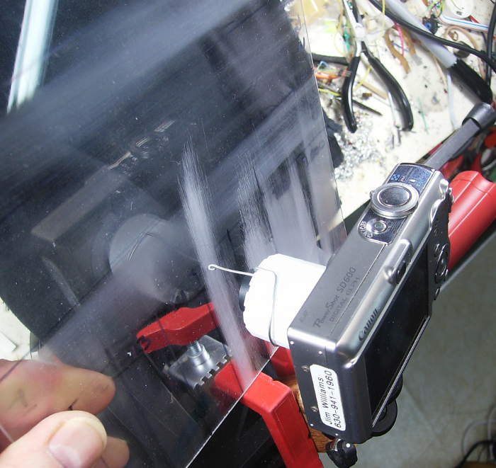
  Arduino dangling) on a stick hanging out in space so it could see past various obstructions, “up” a small staircase, and along the floor on the next level. At 50% duty cycle and 50 mA, it worked for the full 44′ shot. (11′ down the computer bench, 6′ to the stairs, 7 ft “up” the stairs, and 20′ across the
 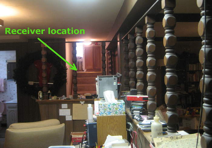 kitchen. View from the LED is on the left.)
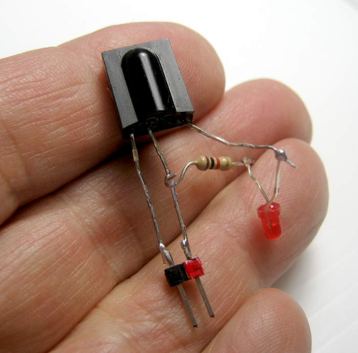 Trying to get better results, I made up another simpler receiver, using a different IR module and just an LED. After verifying that this one was indeed open collector (the RS one wasn’t), and getting past some dumb mistake, I second guessed myself and made it and remade it so the LED would be on, then off, then on
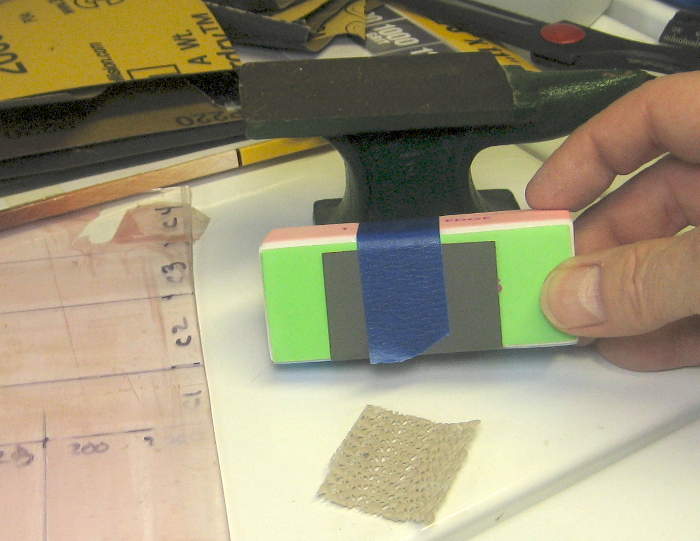
 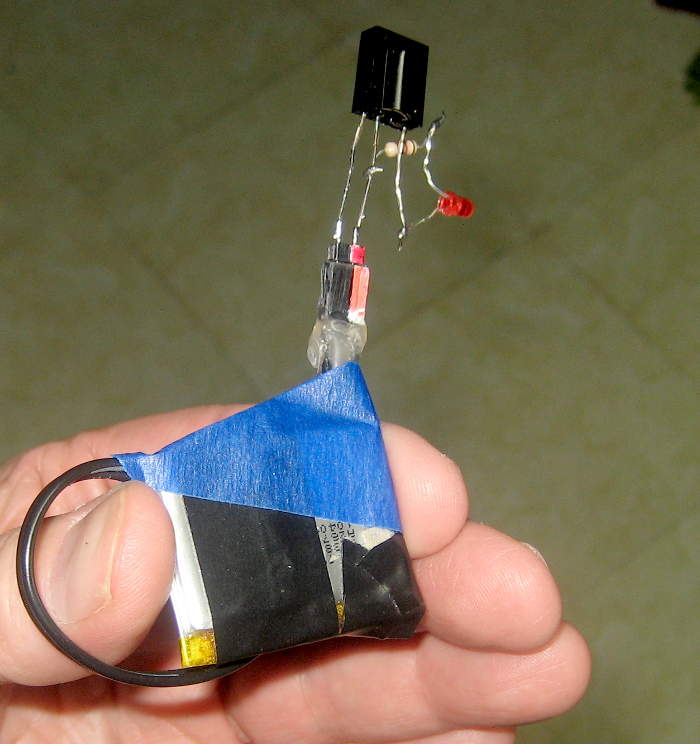 when pulses were sensed to make the most usable tool. (Is it easier to see it stutter off or on at the ragged edge of range?) Here it is as used, with some random little LiPo cell.
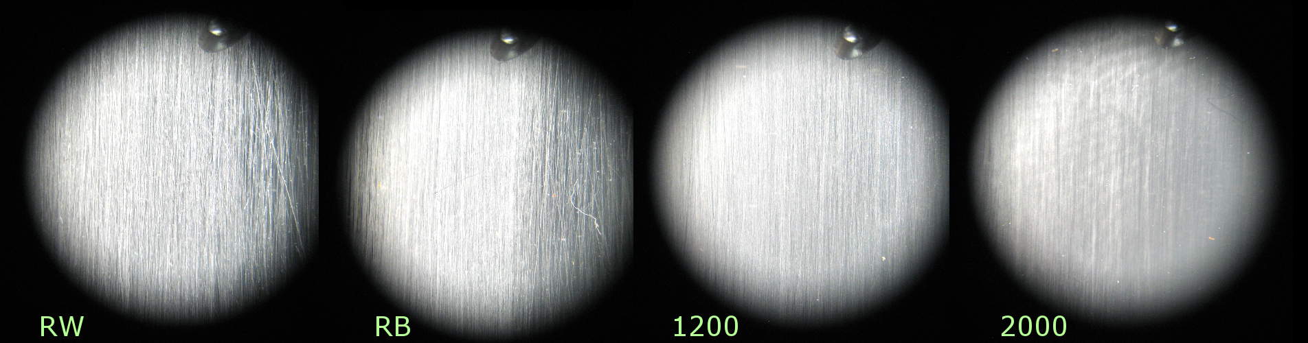
 Trying to decrease the range (to make measurement easier) while staying pretty linear, I made a little diffuser/attenuator out of a bit of plastic tube that (when split) fits over the (5mm) IR LED and has a Kleenex cover taped over the emitting end as the diffuser. I can’t imagine its effects could be brightness dependent. It might, however, act as much more of a point source, changing the parts of the range behavior related to the narrow beam divergence created by the LED’s lens. Ugh.
 The new receiver, tested with the diffuser shows the expected (and unimportant) behavior of somewhat shorter range (~72%) when DC is reduced from 50% to 20%. For the payoff test of decreasing DC and increasing current by like ratios: Using the 20mA->50mA points nets a 15% range gain. Using 10mA->(interpolated) 25mA gives a 32% gain. That’s probably statistically significant, though hardly a “Hallelujah!”.
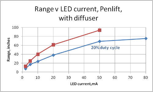 Data from the penlift – including its protocols – with the diffuser provides similar range decrease (66%) in the irrelevant dropping DC test. The payoff tests – two pairs of direct data and one interpolated – gives an average range gain of 8%. Big whoop.
 with reduced DC. But the payoff tests – real data for 2->5mA and extrapolated for 5->12.5mA (ran out of room to go any farther!) average 62% gain. But there’s a partial explanation: Graphs of both data sets covering several points (the ones with diffuser) show a clear curve – with greater slope at low currents. Since the scant data points we have are at the bottom, steepest part of the curve, one could argue that current increases have more effect there. But (in a fit of sensibility!) I haven’t done any curve fitting to see if that’s justified.
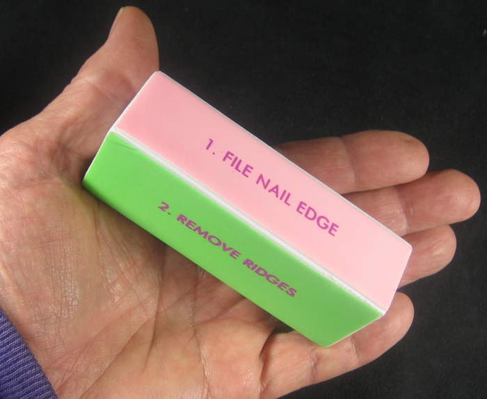


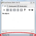 Update 4/29/16: I discovered the problem that caused my inkscape prints to Retina Engrave to work wrong: I had the “Opacity” set to less than 100%. Apparently RE doesn’t like that. It had become a default value, and all docs created since that happened were so corrupted. Changing the opacity back to 100% (and making sure it stuck as the default!) completely fixed the problem. Who knew?