
Introduction
I was planning to hold this to be part of a much larger writeup of the Drawbot, but while it started as part of that project, it sort of took on a life of its own as an IR comms optimizing exercise. I blew a huge amount of time on this, sticking my head in the sand and ignoring other things I really should have been working on. I kept thinking “just one more test” – but that wasn’t how it worked.
 The first version of the pen lift for the Drawbot included a nice servo mechanism driven by a Tiny85, but time forced the major ugliness of a light pair of wires from the main Arduino to carry control info to the gondola. It worked fine, but those wires were never supposed to be there. IR communication was the plan.
 Finally, using a (20 year?) old 3 pin 38KHz IR receiver still in its Radio Shack bubble pack, I made up a PCB
 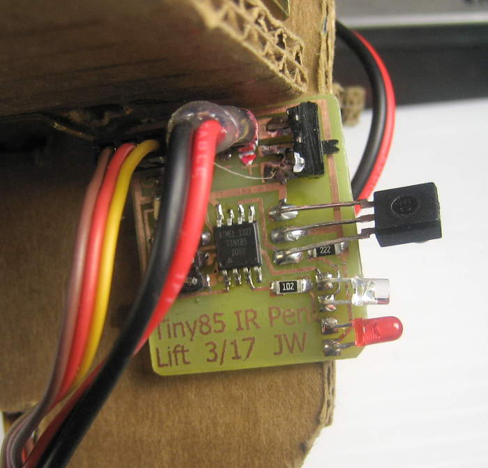 with a Tiny85 listening to the receiver module, driving the servo to lift the gondola and red and green status LEDs (for pen down/up). I defined a simple pulse position protocol (in DrawbotStuff/DrawbotTinyServo4_IR.ino) on top of the required 38KHz pulses to deliver the 1 bit (up/down) messages, made up a test sender with an Arduino and an IR LED sending alternate state messages every half second and got it working.
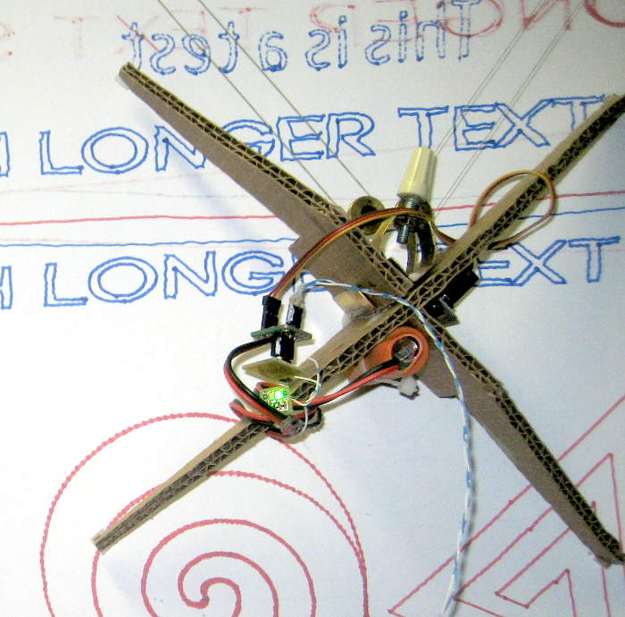
 A little aluminum bracket glued to the back of the PCB clips it to the gondola. Servo and power wires were both perfect length to go to the board. Sometimes we just get lucky. 🙂
Unfortunately, I wondered whether a useful improvement in range could be made by increasing LED current, along with a corresponding decrease in pulse width. Now, the plan is to use 3 IR LEDs spread across the width of the Drawbot base, shining up at the gondola so even when it’s at the bottom corners of its movement, it will still have a transmitter LED more or less under it (ended up with 6). And with one LED at 50% duty cycle and 20mA – completely within the LED’s specs – I can get range much greater than to the top of the Drawbot. So it really doesn’t need any range improvement. But I just had to go and ask the question. Bad decision.
Rick S suggested a 50% duty cycle would contain the most energy at the fundamental, thus providing max signal after the receiver’s bandpass filter. Sounded like a reasonable argument against a range increase. I tested at the space with 5.5 mA/50% DC pulses and got range (go/no go, with the actual receiver and protocol) of 50″. Dropping to 25% DC but still 5.5mA, range dropped to 40″. I can believe that. Keeping 25% and increasing current to 11mA range went up to 167″! WTH?
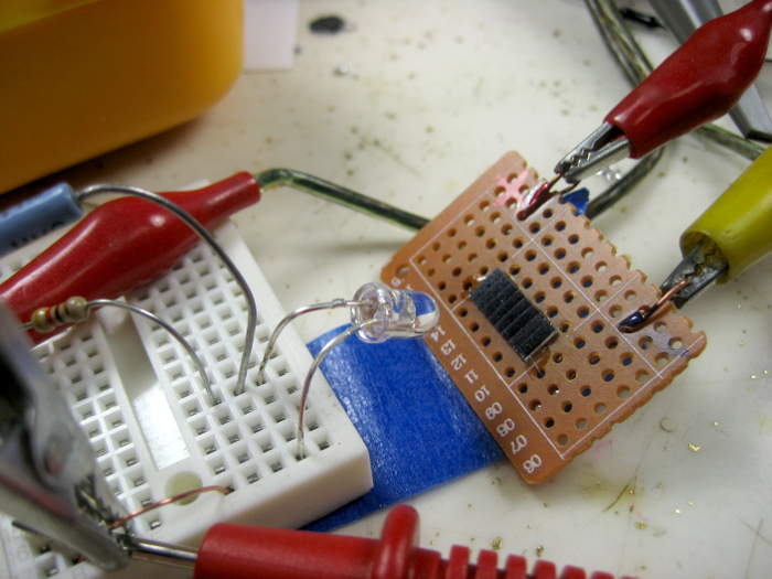 Christine suggested maybe the LED output was nonlinear and at the lower current wasn’t putting out as much as expected. I tested with a very small 8 cell Si solar panel directly into my bench meter in current mode (~100 ohms),
 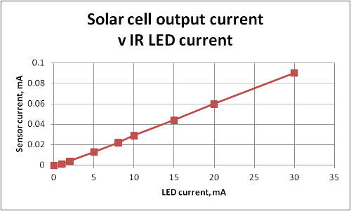 which I think is a good way to test for light energy in. (I crudely covered the panel to keep out ambient light.) Results of output current v LED drive current were VERY linear, 1-30 mA. So I think doubling the current does indeed double the light output.
(A vaguely plausible explanation for the wild range increase (sorry for no pics 🙁 ): The test was done with the LED near the end of one of the gray tables at the space, maybe 5″ above its surface, and aimed horizontally. *Maybe* – energy off axis, which should never have come into play, hit the table top and reflected/diffused off toward the 167″ away receiver over another table. That effect could be eliminated by mounting the LED out in space, not over a possibly reflective surface. A subsequent test with similar currents but without the problem table did not show the wild range increase.)
Of course while testing using the actual intended receiver and message protocol provides great “real world” chops, it violates my “No boolean failure indications!” rule. I should really structure a better test indicator. Hmm – if I can’t get inside the receiver module to get an analog indication of how close we are to max range threshold, what if I can control the stimulus – LED current – and use that to sneak up on the indicator? (Interesting idea, cost me lots of time digging into how to get an analog handle on LED current with a bench supply, but never got used. All I did was suffer along with the go/no go indications of the IR receivers. 🙁 )
A good next test would be another doubling (or more) of LED current (with corresponding decrease in duty cycle to keep from blowing the LED) and testing range. Maybe simplify the pulse train to eliminate any funnies created by my protocol, and maybe use a newer (and just different) IR receiver module.
Range test approach
Ugh. The first tests (at W88) were with 2 known resistors that measured a factor of 2 difference in LED current: 5.5mA and 11 mA. I kept the current low so the range would be manageable. But the results were just unreasonable.
For the next round, I wanted to compare the range with a known LED current at 50% duty cycle (of the 38KHz pulses) with the range with a considerably higher current and correspondingly lower duty cycle (to not smoke the LED) – for nominally the same energy per pulse. How hard can that be?
The lowest duty cycle I could easily arrange on the Arduino at 38KHz was 20%:
    digitalWrite(LEDPIN,HIGH);
    digitalWrite(LEDPIN,LOW);
    delayMicroseconds(16);
That gave me a 2.5:1 change from the 50% D.C. (duty cycle) I took as reference. That should be enough to see whatever effects there are by increasing LED current by a factor of 2.5.
 To provide known current pulses, I set the IR LED up with a fixed resistor and an adjustable bench power supply. Pulse current was gated by a logic level MOSFET driven by an Arduino (or sometimes a bench pulse generator).
 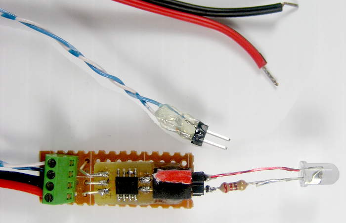 I mounted the FDS6670 MOSFET (in its odd SOIC 8 package) with power, logic in, and load connections so it might be reused some time.
By measuring the voltage pulses across the known resistor (with my nice new scope), I made a table of supply voltage v LED current so I could easily produce any desired LED current. That approach was chosen so changes in the forward voltage of the LED would not affect the results. The first 2 columns below show the results.
I, mA   Vsupply   Vsup, computed
  2       1.55     1.53
  5       2.16     2.26
 10       3.27     3.36
 20       5.57     5.56
 40      10.6      9.88
 50      11.6     11.9
 80      18.5     18.6
100      22.8     23.0
(In hindsight, the limited accuracy of reading the pulse amplitude on the scope introduced more error than the LED. Better would have been to measure the LED’s forward voltage at a couple of currents, measure whatever drop there was across the MOSFET (if any), interpolate the LED voltage and compute the supply voltage. Working backwards and subtracting the drop across the resistor at each current from the required supply voltage in the table above, I computed LED voltages between 0.6 and 1.17V, with no particular correlation with current – awful. Still close enough to be useful – just not very ideal. Measured DC LED Vf=1.19V @10mA. Later I computed the Vsupply based on known Vf (third column above); that’s what I used for subsequent tests.)
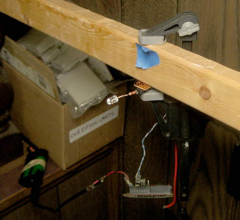 Knowing I’d need a long straight shot, I mounted the LED (with
  Arduino dangling) on a stick hanging out in space so it could see past various obstructions, “up” a small staircase, and along the floor on the next level. At 50% duty cycle and 50 mA, it worked for the full 44′ shot. (11′ down the computer bench, 6′ to the stairs, 7 ft “up” the stairs, and 20′ across the
 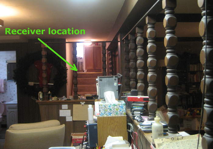 kitchen. View from the LED is on the left.)
Unfortunately, I never got very crisp results. The go/no go indication of the pen lift receiver was too capricious. Once again, I could see some decrease at constant current going from 50% to 20% duty cycle. But when I tried to change current, results were unclear. (Note that the observation of range decrease going from 50% to 20% DC has no relevance to the tradeoff we’re investigating. But it’s a very easy test, and can at least give some warm fuzzies when it behaves as expected.) Hmm – might there have been reflections from the kitchen floor – very analogous to the table in the tests at W88 – confounding the measurements?
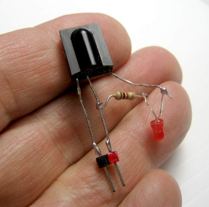 Trying to get better results, I made up another simpler receiver, using a different IR module and just an LED. After verifying that this one was indeed open collector (the RS one wasn’t), and getting past some dumb mistake, I second guessed myself and made it and remade it so the LED would be on, then off, then on
 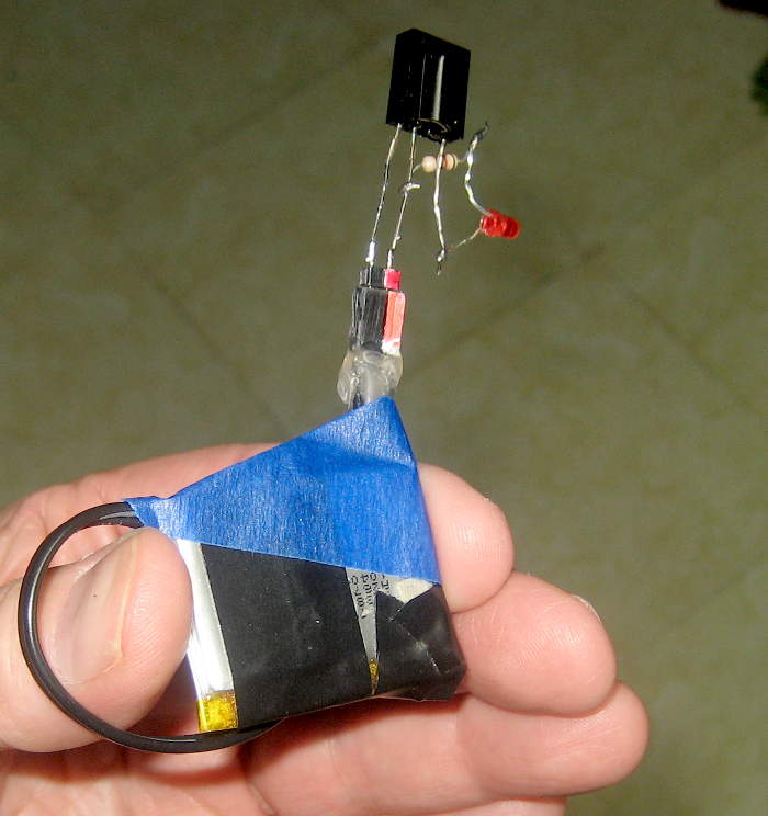 when pulses were sensed to make the most usable tool. (Is it easier to see it stutter off or on at the ragged edge of range?) Here it is as used, with some random little LiPo cell.
But it’s not that simple. In reading the datasheet for the common Vishay TSOP devices, I found you can’t just send continuous 38KHz pulses – something about AGC. It’s designed only for messages, and messages have a maximum length, and dead time is required between messages. That meant I would have to rewrite my test sender, honoring the gaps, but still giving a ‘mostly continuous’ indication on the receiver. Yeah, it’s just datasheets and code and design decisions, and yes, I can do it all, but boo. So I did it. Boo.
 Trying to decrease the range (to make measurement easier) while staying pretty linear, I made a little diffuser/attenuator out of a bit of plastic tube that (when split) fits over the (5mm) IR LED and has a Kleenex cover taped over the emitting end as the diffuser. I can’t imagine its effects could be brightness dependent. It might, however, act as much more of a point source, changing the parts of the range behavior related to the narrow beam divergence created by the LED’s lens. Ugh.
Real test results (finally!)
Using the new supply voltage values, new code on the penlift board, new code on the test driver Arduino, the 3d version of the independent receiver, and clamping the LED on the edge of the bench looking out so there wouldn’t be any possibility of unintended reflections, I did some tests. Finally. To keep from further frying the LED’s resistor (oops), I quit the 50% DC tests early. (I really need to remember to consider power more consistently in electronics hacks. As well as thermal effects in chemical hacks.)
The new sensor (with new “as continuous as I dared” pulse stream) worked, but not great. Its LED was constant brightness (and blinking at ~10Hz), but gently started to dim as it reached max range. Then it went out. I tried to gauge where it just started to dim (what a terrible indication!) and moved just a little closer for the official range. Uncertainty was a couple of inches. Ugh.
The penlift receiver exhibited some kind of hysteresis. I’d move away until it stopped responding, then go closer again so it restarted. But then if I went away very slowly, I could get an extra inch or five. This was over the course of several seconds. Parts of the AGC seem to be very slow. Again, I moved a little closer than the very furthest I could finesse for the official measurement. For both the penlift and the alternate receiver, I moved around in space to make sure I was fairly centered on the beam.
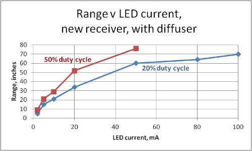 The new receiver, tested with the diffuser shows the expected (and unimportant) behavior of somewhat shorter range (~72%) when DC is reduced from 50% to 20%. For the payoff test of decreasing DC and increasing current by like ratios: Using the 20mA->50mA points nets a 15% range gain. Using 10mA->(interpolated) 25mA gives a 32% gain. That’s probably statistically significant, though hardly a “Hallelujah!”.
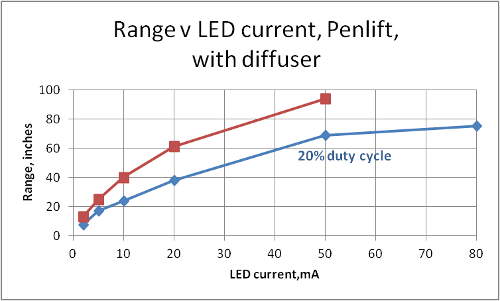 Data from the penlift – including its protocols – with the diffuser provides similar range decrease (66%) in the irrelevant dropping DC test. The payoff tests – two pairs of direct data and one interpolated – gives an average range gain of 8%. Big whoop.
The penlift with naked, lensed LED – the configuration I had expected to use all along – again gives similar range drop (70%)  with reduced DC. But the payoff tests – real data for 2->5mA and extrapolated for 5->12.5mA (ran out of room to go any farther!) average 62% gain. But there’s a partial explanation: Graphs of both data sets covering several points (the ones with diffuser) show a clear curve – with greater slope at low currents. Since the scant data points we have are at the bottom, steepest part of the curve, one could argue that current increases have more effect there. But (in a fit of sensibility!) I haven’t done any curve fitting to see if that’s justified.
The bottom line
Results were mixed, but it does look like increasing current and decreasing duty cycle, here both by a factor of 2.5, increased range by 10% – 30%, possibly more in some cases. Interesting.
But putting my adult hat on for a moment, this was all unnecessary for the case at hand: At just 5mA and 50% DC, the penlift worked out to 16 feet. The farthest the gondola can ever get from the LEDs is a little over 3 feet. But once some dumb question insinuates itself into my head, rational behavior is out the window. Ugh.
Update some months later: The actual drawbot pen lift works perfectly with this overengineered comms mechanism.
Notes on IR receiver modules
For at least my future reference, here are some random bits I learned diving down the IR receiver rabbit hole:
- The receiver modules are cheap and wonderfully effective. Just use one!
- They come with center frequencies from 30-56KHz. It doesn’t matter which you use, but do be sure your transmitter matches it.
- There are several quite well documented control protocols used by commercial remotes. The IR receiver docs often include nice info on them.
- These things are expressly designed for delivering small (a few bytes max) asynchronous messages, and REQUIRE gaps between them. They’re NOT designed as general purpose comms links.
- They will (usually?) detect the beginning of a pulse stream in well under a millisecond. But their AGC/other internal timing is very much not designed for DC carrier. Don’t try to use them for a (normally on) beam break application!
- There are multiple versions of modules tuned for different use cases. I ran across families supporting “AGC 2” and “AGC 4”. Presumably there are at least two other AGC classes. There are versions for “short” and “long” data packets, and something called “continuous”, though it might need gaps as well. I’d guess they would all work for simple hobby applications.
- If you can’t get a datasheet for a junkbox/surplus IR receiver and don’t know the pinout, the following is alleged to have worked well and never fried any parts: With a 1K resistor between the power supply and the device (for safety), just try all the possible pinouts of power/ground/signal out while shining a TV remote at it until you find the one that works.
Pingback: Drawbot string plotter | Jim's Projects