OK, the battle has begun. That darned GFCI outlet has refused to let my Christmas lights run in rainy weather too many times. It’s time to understand this stuff and update my installation techniques so I stand a much better chance of not getting bitten by this again.
(Just to be clear: I’m NOT complaining about rainy weather at Christmas time. Snow is beautiful. Unless you have to drive in it. Or walk in it. Or shovel it. Which I do. So above freezing temps in the winter are OK by me.)
Understanding GFCIs isn’t hard. They just look for differences in current in the hot and neutral conductors, and if that difference is ~5mA or more, they figure someone might be getting electrocuted, so they shut the power off. I’m all for that.
What I don’t understand is exactly where at least the worst of that leakage current is happening in my holiday lights. Once I understand that, the goal is lengthening the short circuits so they don’t scare the GFCI into shutting the power off again. Woven into that is separating fact from myth about what matters when trying to make GFCI-friendly wiring for outdoor lights.
This project note is work in progress, and will be updated as progress occurs. Maybe a good way to manage that once it’s done and working (or failed or whatever) is to rewrite the final story, put it at the top, and keep all the historical ramblings at the end, after a well marked break. (Spoiler alert: There’s a way simpler solution at the end of this post.)
Boolean failure indications
Part of what makes troubleshooting something like this difficult is that the indication of the problem (a tripped GFCI) has only two states: No Problem and FAIL.
When I co-authored a troubleshooting manual at the last place I worked, I implored the wannabe troubleshooters to avoid getting stuck with a boolean failure indicator. Lie, cheat, steal – do whatever it takes to get your hands on the instantaneous value of whatever variable triggers the failure when it crosses a threshold. Get a private code version, use undocumented interfaces, run a debug kernel – but somehow get something that shows whether the changes you’re making are helping stay away from that dreaded threshold value.
(Update 3/20/17) In some cases when you really can’t get your hands into the trigger mechanism, maybe you can get more analog-y info by changing the input stimulus. This came up while investigating range of IR remote controls. While I couldn’t get into the black box TSOP-type 38KHz IR receiver, I could alter the amplitude of the IR signal I was sending (by changing LED current). This might let me sort of alter the trigger point in a way I could control.
Measuring leakage current
That advice obviously applies here – but how do I get my hands on the magnitude of the couple of mA of current leaking to the wet ground? How about the way the GFCIs do it? A classic error of beginners with an amprobe type clamp-on AC ammeter is to try to measure current by clamping it around say a piece of lamp cord. Of course that doesn’t work, since the current in the two conductors is exactly equal and opposite, and they exactly cancel each other out.
But in the GFCI leakage current case, the currents through the hot and neutral conductors are not quite equal. If we run both main conductors thru a current transformer, and if our transformer is sensitive enough, we can use it to measure the difference in the currents – which is exactly what we want. And if I could build it into a device with an AC plug and socket so I could plug it inline with the outdoor lights, I could measure the leakage – and more importantly, the changes in leakage as I did various tests!
If there were enough leakage to trip the GFCI on the outdoor outlet (a likely case if it’s wet enough out to do this testing), I’d have to resort to an extension cord from a non GFCI outlet. Yeah, I’d be outside standing on the wet ground doing unusual things with the light strings – the perfect recipe to get a shock or worse – so I’d better be extra careful with this non-protected setup.
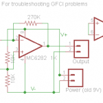
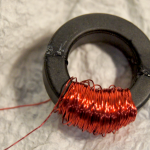 My old current sense toroids might work with a suitable amp. I couldn’t easily create tiny current differences, but since I only care about the difference, if I run say 5mA of AC thru a turn or two through the toroid and if the amplified output is enough to work with, it might work. I can get one turn of a pair of most any conductors through the toroid, but if I cheat and use say 16 ga wire, I should be able to get several (2-conductor) turns thru the core, making the whole design easier. The total draw of the lights would almost certainly be within the ampacity of that #16 wire.
In initial play, I’ve been able to get ~0.5VAC out for 5mA thru the toroid core, though with a really distorted waveform. Hum has been a real nuisance. Maybe an isolated, battery powered design would make that less of a problem. That 10uF (!) across the toroid was to get rid of RF it was picking up from a local AM station.
Another approach would be to hack a real GFCI. (Spoiler alert: That’s probably the way it will be built!)
Possible improvements to test
The changes I’d like to observe the results of with my leakage indicator so far are:
- Blow outlets and plugs out with compressed air.
- Spray WD-40 in/on outlets and plugs.
- Raise outlets/plugs off the ground.
- Disconnect specific strings of lights.
It will also be interesting to compare the leakage at above v below freezing temperatures.
I expect the final wiring will have outlets on spikes off the ground, covered and with their holes pointing at the ground. But that won’t be something I can see immediate results from with the tester like lifting outlets off the wet ground.
Hacking a GFCI
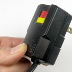
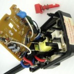 I had a line cord cut-off – probably from a hair dryer – with a GFCI plug, so I opened it up to see how hackable it was. Interestingly, while there was a little PCB inside, the control circuitry had no active electronics (no amp after the current transformer). The mechanical latching relay that opened both line and neutral when it tripped was operated by a solenoid powered (presumably) by just the current from the transformer due to leakage. The contacts were spring loaded open, and the red Reset button and its (stronger) spring held the contacts closed until the solenoid released the latch and allowed the contacts to open.
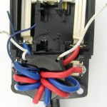 As expected, both main conductors passed through the toroidal core of the current transformer. There were two interesting features. First, the main conductors made 4 turns around the core, making it more sensitive than a single turn. Second, there was a separate, much thinner primary winding (the thin blue wire). That must have been for the test current. A nice simple, robust bit of engineering.
When I put ~8mA through one conductor of the main winding (a 0.11uF cap across 120VAC), I measured about 59mVAC across the secondary (white wires). That should be plenty of signal to work with as input to an op-amp. And with the PCB and the solenoid removed, there’s a good chance I can squeeze a little PCB with my electronics inside the shell to make a reasonably robust test tool. (If I want audio output, that will almost certainly require another box, if only for the speaker.)
If this approach works out, I should tear some other common GFCIs (like ones built into outlets) apart to see if I can make a general recipe of how to make a tester starting with most any (probably defective/free) GFCI. Presumably all we’d need is the current transformer.
My tester
The main purpose of the tester is to provide real-time feedback on the leakage while I make changes in the wiring. A secondary purpose is to provide a snapshot measurement of the leakage to see how close it is to the 5mA trip level. Here are some requirements.
- Must provide some analog indication of leakage current. (Sound would be convenient.)
- Range: From <<5mA (far below GFCI trip) to maybe 20mA. (And don’t blow up if >> 20mA!)
- Should provide a calibrated output probably readable with a voltmeter. Could be AC or DC. Decimal point doesn’t matter – could be say 0.5V for 5mA.
- Should provide an audible output that varies with leakage. Likely is a single tone, probably higher for higher leakage. Others would be considered – like spoken values.
- Give the guy on his knees under the bushes a quantitative indication of how much good that spray of WD-40 is doing. How about having the audible tone drop 1 octave for every factor of 2 change in leakage? With 10KHz as top, 4 or 5 octaves would give a range of 2^^4 or 2^^5. Four octaves and 20mA max would give good quantitative indication down to 1.25mA.
- A range switch would be considered.
- A reference tone for 5mA would be very nice. Maybe every 5 seconds have a 400ms silence, 200ms of the 5mA tone, silence, back to real time tone?
- The droning tone would probably get very irritating pretty quickly. How about a mute mechanism that shuts the tone off if no change in leakage for say 5 sec? Any change turns tone back on, maybe automatically starting with a 5mA reference tone cycle. Might have sensitivity control for what constitutes “change”. Reference for “old” leakage remains until tone is on again. That is, a very slow change in leakage would always trigger the tone after while.
- Maybe if no change for say 10 sec, would show how we’re doing with 1 sec of current tone split with above 5mA reference tone.
- For leakage above the 20 mA max, the tone is audibly different – maybe on/off at 1Hz.
- It would be very nice if it were robust and self-contained enough to be able to offer to lend it to others struggling with GFCI trips on outside lighting.
All that tone generation/change stuff would be pretty simple if the tone were generated by say, a Tiny85. If the leakage current were mapped by analog amp/rectifier to full scale of the 10 bit A/D at say 20mA leakage, at 2^^4 less (1.25mA) we’d still have 64 A/D bits to notice changes. That sounds like a pretty usable range. The analog section would probably have to have a trimmer to calibrate to the A/D full scale.
How to provide a power supply for both the op amp and the Tiny (and probably an audio amp!) is open. Before the Tiny, the plan was to use a past-service-life 9V battery. If the Tiny’s ratiometric A/D reference is used, Vcc would have to be regulated. Probably using the 2.56V internal reference would be better. And since the A/D input absolute max is Vcc, if I regulated the Tiny Vcc to say 5V and the op amp power supply were such that it could never put out > 5V, the requirement of not blowing up for leakage > 20mA would be ensured.
Hmm – I suppose if the design power input were ~7VDC (split for the op amp, regulated for the Tiny) it could use a new or used 9V or a 2S LiPo. (Yeah, or 6 NiMH AAs. But that’s pretty clunky.) Maybe just a 9V clip on a little pigtail and a rubber band to hold whatever battery on? That could serve as the power switch as well. Since a minor goal is being able to lend the device out, if I put together a 2S LiPo (with 9V style snaps), I’d need to provide a suitable charger to go with it. Yeah, I could do that. Or let the guy buy a 9V. Needs more thought.
Having my hand forced
The tester is only some wires and an op amp on a breadboard (plus some hot air) so far, but the darn lights have been out for a couple of days. I need to get them back on.
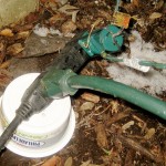
 The first step of the attack has been getting the connections off the ground. Plastic containers have been the first approach. I also raised up outlets with no lights.
An additional step was to charge up the portable air tank and blow out all the plugs and sockets with compressed air. It really hurt to do that without being able to see if/how much it helps, but I really, really wanted to get the lights back on.
I think I’d tried resetting the GFCI earlier today, and it wouldn’t hold. After raising the connectors and blowing them out, the lights stayed on, so I accomplished the immediate goal. Unfortunately, it’s many hours after that initial test, it’s now below freezing, and I didn’t test before hauling out the air and cream cheese containers. Yeah, the goal was to get the dumb lights back on and it was dark and late and cold, but it wouldn’t have killed me to do a quick test first. 🙁
Update 2/24/14: After having been buried in a foot of snow for weeks, a melt uncovered the wiring for the Christmas lights. On a whim, on a day when temps were maybe 20F, I tried the lights. Despite cords having been knocked off their plastic perches, the lights lit and didn’t trip the breaker. Not particularly relevant, but it’s another data point on a well-below freezing day. I think GFCI trips are a lot less likely when it’s below freezing.
I might not need/get to build this!
1/14/21: The lighting season started with a lot of rain – and GFCI trips. After more reading and head scratching, I realized/reasoned that a very likely source of leakage was outlets (female) that water had gotten inside. (Ron Sea proposed precisely this solution in the comments below. Thanks, Ron!) Unless the outlet is specifically designed to prevent it, there’s a nice short possible path for water to create leakage from hot to green wire ground inside the outlet. That’s certainly not the only possible path, but it is an obvious one.
While it seems heretical to step away from the conventional wisdom of “Always use 3-wire extension cords outside!”, I think it’s the enemy here. That third wire is there to allow for example the metal case of a tool to be grounded to protect against a hot-to-case fault in the tool. But if the only purpose of the extension cord is for 2-wire lights, that case does not come up, and in fact nothing useful is ever even connected to that third ground wire. (Sure – if you’re using the cord for the lights to run your old metal-case electric drill while putting up the lights, you want that third wire! But not for just the lights.)
I argue there is no typical case where the third wire provides any additional protection in the pure 2-wire lights case. But there is a clear and present possibility of inappropriate GFCI trips when the 3rd wire is present and connected (and wet!).
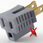 So I suggest a valid and potent ally in the GFCI battle is a ‘cheater’ adapter – to disconnect that third wire. (Of course, just using 2-wire extension cords provides the same effect.) I put one in front of all my Christmas lighting wiring and saw no more GFCI trips for the rest of the season. I plan to continue the practice going forward. (In my case, I have some custom, semi-permanently installed 3-wire extensions for lighting, so 2-wire extensions are an awkward solution.) Of course I’ll still arrange all exposed outlets to be off the ground.
It would be interesting if all the clever design above was for naught, made unnecessary by simply disconnecting one wire.

I too have struggled for years with the problem of a GFCI tripping when it rained while my outdoor Christmas lights were on. I am an electrical engineer, so I understand the basic principles, although my specialty is not home wiring and safety. Many years ago, when I lived in a house that did not have GFCI’s, I used isolation transformers to provide safety for my outdoor wiring. With that setup, the outdoor lights were powered by the secondary of the transformer which had no direct electrical connection to the grounded house wiring. I figured that would provide safety, unless the transformer had some kind of internal short circuit (I tested for that with an ohm meter to make sure it was really isolated).
When I moved into a more modern house that had GFCI’s protecting all outside outlets, I got rid of the isolation transformers, figuring that the GFCI would actually be safer, and it simplified my wiring as well. However, from that point on, I had problems every year when it rained, due to leakage current tripping the GFCI. The place where I plugged in my outdoor extension cords had an “in-use” cover that protected it from rain, so I figured the current leakage had to be at the point where one extension cord connected to another, or where the light strings plugged into the extension cord. So next, I got long enough extension cords to reach each light string without needing to join extension cords in an exposed location. I also carefully arranged it, so that the plug ends of the extension cords (where the light strings plugged in) were at least a foot off the ground, and faced down. It still didn’t solve the problem when we had heavy rain and wind. (Note – we don’t get snow where I live, so there is no chance of the connections getting buried in snow accumulation.)
One year I tried zip lock bags and tape to protect the point where the light strings plugged into the end of an extension cord. That made it worse because moisture still somehow got in, and then the bags held the moisture instead of letting it dry out after the rain stopped. I regretted disposing of my isolation transformers, and this year I started searching for isolation transformers online. They still exist, and you can get one rated at 250 – 300 watts for a little over $100. I was almost ready to order one, when I thought of a different solution, based on the way GFCIs work.
All the outdoor extension cords I’ve used have 3 prong outlets, with a ground connection. That is certainly a safety feature when using outdoor tools with a grounding plug, such as a metal electric drill. However, Christmas light strings never have a ground wire, so their plugs only have two prongs. Thus the ground hole in the extension cord socket is not used and is exposed to the weather. A GFCI will trip whenever the current in the hot and neutral wires does not match. That can only happen it there is leakage somewhere. The GFCI does not know where the current is leaking. If someone outside touches the light string and current leaks through their body, the GFCI will trip, and that’s good. But if the current simply leaks into the unused ground hole in the extension cord socket, the GFCI will also trip, but that small leakage is causing no harm – the leakage current is simply coming back through the ground wire in the extension cord instead of the neutral wire.
So I started thinking, why not use outdoor rated extension cords that don’t have a ground wire at all? Then the only way current could leak is if the light string touched a person or some other object that was grounded, and in that case the GFCI would still trip, which is a good thing. Since it is hard to find outdoor extension cords with only two wires, I decided to try using one of those adapters that allow you to convert a three prong plug into a two prong plug and use it so that the ground wire in the extension cord is not connected to anything at all. (Another solution could be to simply cut off the ground prong on the three prong extension cord plug.) Then at the socket end of the extension cord (where the light strings plug in), I would fill the ground hole with silicon to seal it from moisture. Thus, this extension cord would be converted into a two wire cord instead of three wire, since there would be nothing connected to the ground wire at either end. This cord would then only be used for Christmas lights since it would not have the three wire connection you would normally need for outdoor tools. The GFCI will still trip if there is current leakage due to someone touching a light string, so it should be safe.
I will be trying that this year to see if it solves the problem. I will update later on how well that worked this season.
Hi Ron,
That sounds like a great idea. Please post back with your results!
Jim
Leakage to ground wouldn’t necessarily have to be to the ground conductor. You could have lights leaking current to the eves troughs or anything wet.
That’s right. And that’s the case where you do want the GFCI to trip. That should still occur with my scheme of removing the ground wire from the picture. You still need to be careful to keep the lights away from any metal objects, or wet soil, etc. I don’t know how much leakage can come from the light strings themselves, and it probably depends on their quality (they should be outdoor rated and not too cheaply made).
I wrap some of my light strings around the trunks of tall trees. If it happens that current leaks from the light strings to the wet tree trunk, I suppose it could trip the GFCI. I will see if that happens, if we get some good strong rain storms this season, and I will post the results later. If that does happen, then next year I will just have to buy some isolation transformers.
This is one of the best discussions of GFCI problems I have found yet!
I have to compliment you Jim. You do things right and solve the problem. I’ve tried air-tight connections, plugging ground plug holes and the like, but to no avail. The GFCI trips when it rains for a long period, and troubleshooting by removing strands has revealed that it’s the totality of the leakages and not necessarily a single current leak. So I’ve decided to just do a little risk management with my Christmas lights over the past two years. When the Christmas lights go up, the garage (and outside outlets) GFCI is replaced with a regular outlet. When the lights come down, the GFCI goes back in.
I am book marking for any updates on what you all have found.
Why do the Tacky Light houses with the million lights keep theirs up so consistently without tripping anything?
Well, it’s Dec 22 now, and we’ve had a couple good rain storms since I put up the lights, and the GFCI tripped both times. I eliminated the ground connection in all my exposed cords, so there must be some current leakage from the light strings to the wet tree trunks. Since I have about 7 trees with light strings wrapped around the trunks, all on the same circuit, I guess the odds are high that there could be leakage somewhere.
The only thing I can think of next is to try isolation transformers, like I did years ago, before there were GFCIs. I’ll have to calculate the power load to see what wattage the transformers will need to handle. I will let you know how that works.
Bummer. Thanks for at least providing a new data point about the ground connection in the power cords not contributing (at least in your case).
Of course an isolation transformer should do the trick. But real ones are expensive. A quick look around for DIY versions just found the standard back to back pairs. The one on Instructables was only a few 10s of V-A, not nearly suitable for this. Some suggested power trannys from old UPSs. Unfortunately, I only have one old UPS I could steal one from. But what about old microwaves? Those have to be near a KW, and are fairly plentiful. Potential article title: “Old microwave transformers: Not just for making spot welders any more!”
The spirit of my (still unmade) audible leakage detector was that I could go around lifting cords and lights off the ground, or otherwise moving things around to try to find the large contributors to the leakage. With the number of lights you have, an audible device could at least let you go around unplugging strings or rearranging things to find the worst offenders. I’d lend you mine if I had one. 🙂
But (especially) for a large installation like yours a great approach might be some kind of visualization apparatus that highlighted the leakage. Kind of like thermal imaging, but for leakage current. I have no idea how to make such a thing, but if anybody has any ideas, post them here!
Pingback: IR comms considerations (for penlift for the Drawbot) | Jim's Projects