
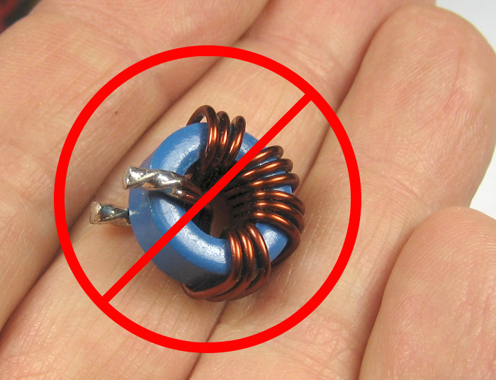
 Toroids with many turns of secondary winding are very useful for AC current sensing and measurement because you can just pass the wire carrying the current to be measured thru them. (We’re not talking about coils with a couple of wimpy turns for RF – though those can be a good source of cores.)
But unless you can find a good, cheap source of well-wound toroids, you’re faced with the really unpleasant task of threading hundreds of turns of fine wire through that core. (Well, unpleasant unless you have one of these cool toroid winding machines. But I don’t.)
After I finally figured out how the machines work, I thought about building one. But there are too many strange and precision parts, especially if you want to wind small cores – which I do. So how do you quickly and simply wind wire on a closed loop toroid?
Cutting
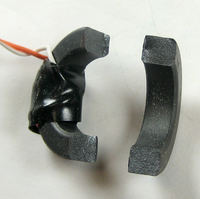
Well, duh – you cheat. If it’s good enough for Captain Kirk… The idea is to cleanly split the toroid in half, wind it, then put it back together. Yeah, it’s magnetically not quite as good after you glue it back together, but it’s good enough.
Fortunately, a ferrite core is kind of brittle, and if you score it nicely, it will often break fairly 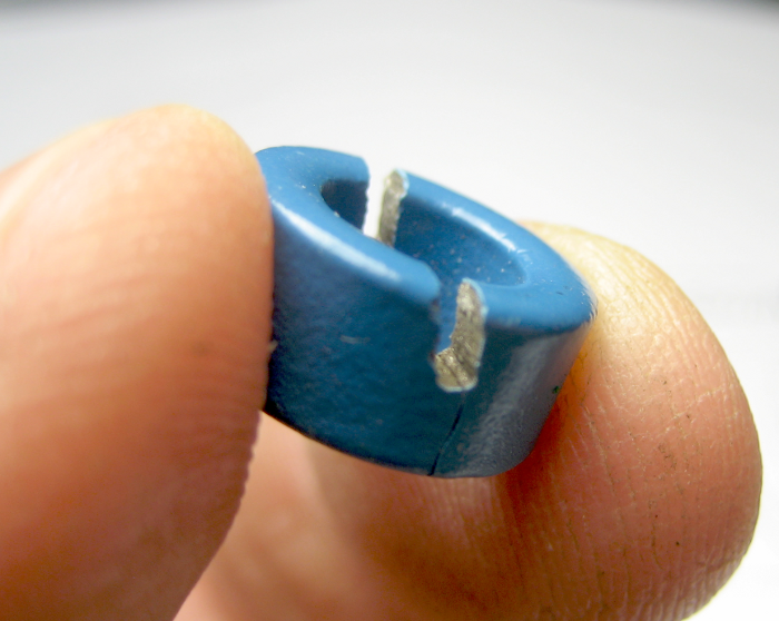 cleanly. I’ve tried a couple of different ways to score them, with varying results. The first was to just saw halfway thru before cracking it. (The material cuts very nicely with a hacksaw.) That approach provided a nice break, but lost so much material that it really felt like performance of the core would be compromised. (I never bothered to wind it.)
 In the spirit of scoring
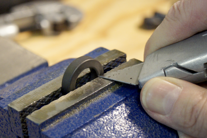
 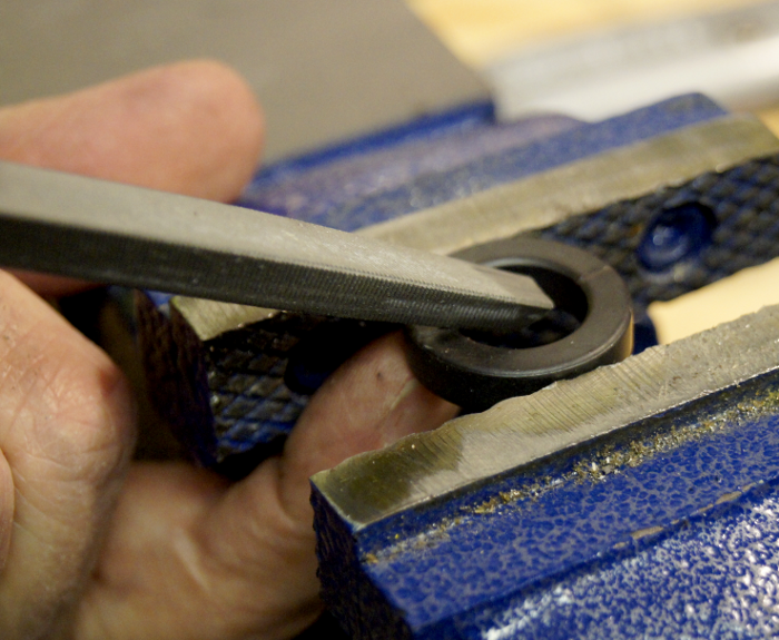 plastic, I tried a Stanley knife. It felt like it didn’t go deep enough to guide the break as much as I wanted. A triangular file didn’t have any trouble cutting the material, but made a wider score than I wanted. In any event, scoring the outside (and inside!) edges, as well as the flat side might help guide the break better.
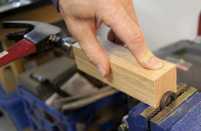 I generally held the core in a vise and whacked it to effect the
 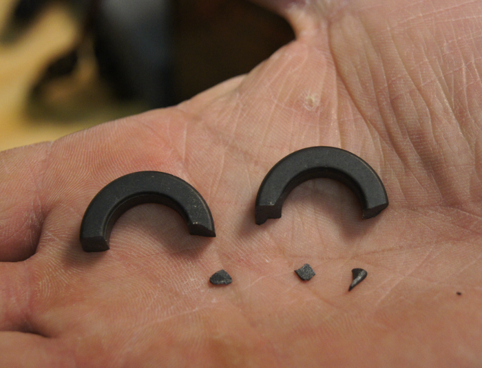 break. Results varied from about perfect to needing some additional reassembly.
The material’s clean breaks make super glue appropriate. By clamping the pieces together tightly, the gap 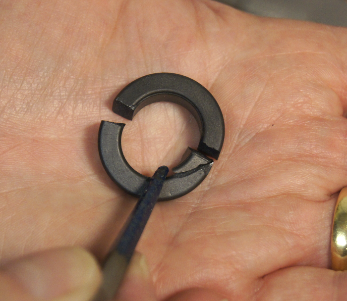 should be small enough to not hurt the magnetic properties too much. When there are chips, it may be easier to glue the chips back carefully as a separate step before you put the two halves back together. If there are chips missing, abort and try a new core. An air gap in the core is exactly what you DON’T want.
Winding
While you could wind the secondary by hand, my strong first choice would be to let 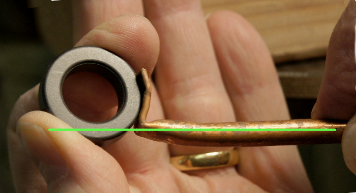 a drill or something turn the core while I guide the wire. We’ll need to attach some kind of spindle to the core to do that. Most of the winding will be about midway between the two breaks, so that part should be on the centerline of the spindle to minimize wobbling.
You could use a dowel nicely shaped concave to fit up against the core as 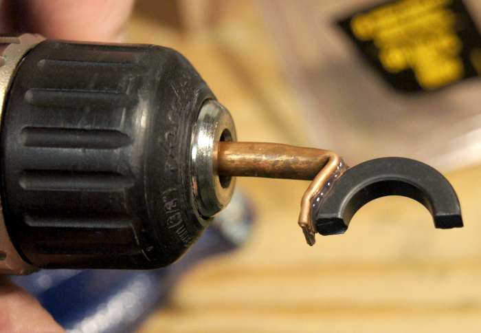 the spindle, but the bottom would probably (underlap?) interfere with some of the windings. Some copper or aluminum tubing lets you take advantage of the part of the core that won’t get any wire as a glue surface. If you handle it gently while winding, hot melt is a great way to hold the spindle to the core half temporarily.
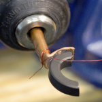
Clip of live winding
It’s nice to know about how many turns you’ve put on so you can confidently make an identical one or vary the number of turns as you experiment. Having a helper to count the turns is convenient. Another, probably less accurate approach is using an estimate of the average diameter of one turn of the winding and the desired turn count to compute how much wire it will take. Pre-measure the wire, and when you run out, you’re done. In any event, chuck the spindle in a drill, tie off some wire so you’ll have a nice lead to work with and start winding! Thanks to Ti Leggett at Workshop 88 for the video. It’s also posted on the W88 blog.
Unlike with some fussy RF coils where you have to worry about losses distributed through the bulk of the core, it doesn’t really matter where on the core your secondary windings are. Having them all bunched up together is fine. But if you’d like to spread them out a little more (perhaps to leave more room for the primary wire in a very small core), it seems like if the drill/whatever is turning slowly enough, you should be able to move your wire-guiding hand back and forth in sync with the rotation such that the extended edges of the winding were neatly wrapped square around the core like the ones in the middle. I’ve tried it, but with only very limited success.
Putting it back together
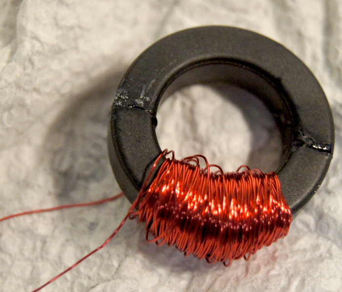 Super glue seems good because the breaks are clean and it introduces such a minimal gap at the joints. Here’s a 1″ O.D. core wound with 200 turns of #30 magnet wire and glued back together. Something like epoxy, that provides filler and some thickness to the glue joint would require that you clamp the core halves together quite tightly to squeeze out as much glue as possible.
If you’d like a little more physical strength and robustness – perhaps for a current transformer you were going to put around the main AC feed wires in your breaker panel – one possible approach would be to include a narrow zip tie on the outside of the core under the winding before you wind it. After you glue the core halves together, bring the ends of the zip tie around the top of the core and pull it tight. If you were quick, it could even provide clamping while the glue dried. (Sorry – no picture. I’ve never tried it.)
Now what?
You must have had some reason to wind that coil in the first place. If it’s for a current transformer to measure AC current, you’ll need to terminate the secondary in a very low resistance, and figure some way to measure the secondary current. You’ll probably also need to do some calculations (or at least testing) based on the material and dimensions of the core to see if it will stay linear (not saturate the core) over the current range of interest.
If you just need to sense AC current – for some kind of logging or perhaps automatically turning one device on when another is on, you can probably get away with most any small core. Here’s a note on how I built an interface to an Arduino.
And if you wound wire on both halves of the core, you could make a more traditional transformer. I’ve never tried that.
Good luck with your new toroid!
Update 2/14/13: The W88 blog post made it to Hackaday! The commentors there always keep people honest, and this was no exception. One poster said he had broken cores several times, and there was no way to get the core back together tight enough. He indicated his cores lost an order of magnitude in inductance! I had no quantitative handle how much the gluing cost, but I didn’t think it would be that much. Time to try to measure the reduction I’m seeing.
I hand wound exactly 30 turns on one of the same cores (without breaking it first). I tried a couple of indirect ways to measure the inductance, since I don’t have an inductance meter. (I do have a capacitance meter, and tried using that both by switching the test leads and even by rotating the meter 180 degrees, but neither one worked.)
Extrapolating from the 30- to the 200-turn coil
The first thought was to measure the inductance of the intact 30 turn test toroid and compare it to the 200 turn glued-together toroid. Since inductance is proportional to the square of the number of turns, I would expect the inductance of the big coil to be about (200/30)²=44.4 time that of the small coil.
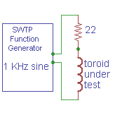
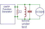 I tried making a tank with a 47 nF cap in parallel with the coil, driving it with my dear old (old being an operative term) Southwest Technical Products function generator and looking at it with a scope. (The 22 Ω across the generator output was to lower the output impedance from I think 75 Ω.) I was going to use the known cap and the resonant frequencies to compute and compare the inductances of the large and small coils. I aborted this after I realized this added a new variable of frequency, and I had no idea how the toroid material behavior changed with frequency.
Update: The setup above is just wrong. There should be some resistance in series with the tank to see the resonance clearly. Thanks to M Peters for his comment below.
To eliminate the frequency variable, I found resonance with the large coil and 1 μF at just about 2 KHz. I changed to the small coil and tried different cap values until I got resonance at 2 KHz again. That was adding a 10 μF electrolytic across the 1 μF film cap for around 11 μF. Plugging those values into a nice LC resonance calculator gives inductances of 570 μH for the small coil and 6300 for the large one. That’s hardly the expected factor of 44, and using the test of a factor of √10, is in fact (barely) an order of magnitude off. But the methodology was poor: Twisting a knob and looking for a peak magnitude on a scope for a low-Q circuit is hardly precise. And electrolytic caps have notoriously inaccurate values at best, and using them at zero volts is completely out of spec. Next approach?
Apples and apples
 The best approach would be to get something with the 30 turn coil I could measure with a decent meter, break and glue it, and measure again. I put a nice carbon resistor in series with the coil, cranked the signal generator to 1 KHz, and measured the voltage across the resistor and the coil with a multimeter whose AC ranges were known good for that frequency.
 I scored the coil with a jeweler’s file and broke it. The break was one of the cleanest I’ve had (fortunately). I used some old (read: thicker than expected) no name cyanoacrylate, wiggled the pieces to be sure they seated as well as possible, squeezed hard and put a spring clamp on it. Then I put it back in the test circuit.
The break/glue happened over maybe 5 minutes, and the test setup was untouched, including the signal generator. I measured the voltages across the resistor and coil again. (Twice for each, as I had done the first time.) This is about as clean a comparison as I can make. So at 1 KHz with a 22 Ω resistor here are the results:
        Vres   Vcoil  Zcoil  L
Before  0.367  0.097  5.81Ω  925μH
After   0.372  0.068  4.02Ω  640μH
The inductance is reduced by the gluing by about 30%. Quite noticeable, but quite acceptable for a hack.
I also did measurements of the tank circuit resonant frequency with the parallel combo of 10 μF electrolytic + 1 μF film caps before and after the break. While there is a frequency difference, I’d guess it doesn’t contribute a large error.
       freq     L
Before 2.0 KHz  576μH
After  2.7 KHz  316μH
That test indicates a 45% decrease in inductance. Not identical, but in the same ball park. Now we have a rough quantitative handle on the impact of break/glue.
Pingback: Toroid winding cheat
Pingback: rndm(mod) » Toroid winding cheat
Pingback: Toroid winding cheat | Daily IT News on it news..it news..
When you cut the toroid apart and glue it back together you change its magnetic characteristics. Because you can’t perfectly reassemble the toroid, the gap left in both cuts reduces the magnetic flux density, reduces the coil’s inductance and causes spurious magnetic fields around the cuts.
exactly what i was thinking…
You could maybe try mixing some iron powder or other fine ferromagnetic material with the glue and see if it improves the reluctance while still maintaining an adequate bond.
good idea, but the mag field will never be the same. would like to see some one actually test this.
There’s an article in March 2013 Circuit Cellar magazine (found at Barnes and Noble) on a home energy monitoring system using current transformers like yours. He uses an AMVECO Magnetics AC1020 1000:1 sensor. Digikey has them for $8.34. He put them on every lead in his home’s electrical load center box.
The first test circuit seems odd to me. All three components are wired in parallel. If the source generator is a voltage source, the scope simply sees the same signal that the generator is driving. The resistor needs to be in series with the LC tank. Maybe the generator has a 50 ohm (or 75) output Z, which would explain it. Why did you need to add 22 ohms in parallel with the tank? The Q of the circuit is much lower this way, which doesn’t allow you to observe a sharp resonance.
Thanks for the comment! In looking back at what I did, you’re exactly right. (That’s why we try to document stuff accurately – so we can look back and see our good designs and our mistakes!) As stated, the 22 ohms was to make the generator (plus resistor) closer to a real voltage source. (I think I’d had some problems with non-resistive output impedance of that generator in the past, and was trying to swamp that out.) But to see the tank resonance by looking at the voltage across it as I’m doing here, there must be some additional impedance (preferably resistive!) in series with the tank.
The fact that I saw a peak at all is thanks to the internal impedance of the signal generator – reduced by the 22 ohms I put in parallel with it! The setup I used is just wrong, and I certainly should know better.
Thanks so much for pointing this out. I hope this will burn it into my brain a little better so I won’t make that mistake again next time.
I wasn’t quite motivated enough to redo the experiment more properly, but I did edit a little mea culpa into the post.
Thanks again.
Jim
Purposely gapping a ferrite core sometimes makes sense, othertimes not.
If you are just trying to make it easier to wind, pre-wrap your wire onto a
dowl rod that can pass through the hole.
Magnetic energy is only stored in the empty spaces between bits of iron
powder or ferrite. Without gaps, a toroid would uselessly magnetize to
its full potential, and thereafter misbehave as-if an empty donut. Not
entirely empty, because the iron still gets hot and wastes power…
The iron’s purpose is merely to guide the field around a confined loop
of very short gaps. Keeps stray fields from uselessly heating the wires.
And shortens the path of the field, so that you get more inductance for
fewer turns and less wire.
Iron metal conducts electricity and supports unwanted eddy currents
that waste power. Therefore it is alloyed, laminated, powdered and
coated, or made into ferrite to block those eddy currents from flowing.
Ferrite does this best and offers the lowest eddy losses. Unfortunately
also offers smallest gap between particles and stores the least energy.
Iron powder offers plenty of gaps to store energy, but conducts small
eddys cause its still metallic iron. And with all those gaps, you need a
LOT of turns to make the same inductance as ferrite.
The ideal thing to do is to use the least lossy ferrite and add needed gap
to store enegy somewhere along the path. If its a big gap, it will have a
messy fringing field, and the wires will need to be spaced well away.
They should cover the gap to contain the field, just not be right in the
worst of the mess. Maybe build up some tape over the gap first…
I have no idea why manufacturers don’t crush up some defective ferrite
cores and re-mold them into distributed gap products to compete with
the iron powders.
So, you need enough gap to store energy or the core quits working. But
not too much gap or you may need excessive amount of wire. Strangely,
counter-intuitively, its not an even trade. Saturation is a problem that
increases with the turn count. Inductance increases with the SQUARE
number of turns. Both decrease linearly with added gap. Adding more
gap, and more turns wherever they will fit, always gives you advantage.
Its a square law vs linear thing…
I really like and appreciate your article. Great.
Thanks, William!
Pingback: GFCIs and Christmas lights | Jim's Projects
Hi Jim et al,
I’m not a regular user here but I found the post with an internet search. I need an rf transformer (1MHz to 2Mhz), so iron core is not an option for me. And high frequency ferrite is much more difficult to cut/machine.
But, I have 1 comment about winding on a toroid… How about winding the coils around the ID and the OD of the toroid?? By that I mean DO NOT wrap the turns radially. The lower value winding goes in the center of the donut shaped core (along the outer perimeter of the ID). The larger winding goes wrapped around the perimeter of the core. No turns are wrapped around the core in the conventional manner.
Since both winding are in the same plane, the core should couple them magnetically.
With regard to making ones own custom shaped magnetics, it should be possible to grind the core into dust sized pieces, then use a microwave oven to melt the pieces into a shape that can be used. There are many videos on youtube about using microwave ovens to melt and recast metal. Induction heating should be an option as well, again there are many examples on youtube.
n’est-ce pas??
73
Art
Hi Art,
Thanks for the reply and interesting toroid winding approach. I’ve never tried it, but I’m guessing it wouldn’t work.
The circular field lines around a bit of current (classic visualization: wire in right hand, thumb along current, fingers show field lines) of all the turns in any coil look for the easiest path. With an iron(ish) core, that easiest path is down the core, essentially concentrating all the field lines thru that core. If that core also goes thru another winding, the field lines also go thru that second winding – resulting in efficient magnetic coupling. Of course the field lines are necessarily complete loops, so for something like wire wound on a nail for a kid’s electromagnet, the field lines must go thru air from one end of the nail to the other to complete their paths. That’s the cool bit about the geometry of a traditionally wound toroid: There’s a complete loop path around each bit of wire ALL going thru iron, so the field is MUCH larger.
If the core is outside, rather than thru the coil – as in your suggestion if the primary is on the ID – I think again virtually all the field lines will go (crosswise!) thru the core. But they still need some path (thru air, unless you add more iron) to encircle the conductors. The shortest (air) path for that is back thru the very center of the coil/toroid.
There’s the rub: If the field lines thru the core are going, say downward (toroid flat on table, coils parallel to plane of table top), the path thru the air in the middle will be upward. Since both the downward and upward field lines go thru the outer coil, they cancel, so there would be little coupling. Or at least that’s what I think would happen. 🙂
But as a wise mentor told me many times – “The test is the test.” Why don’t you give it a try? Shouldn’t be too hard.
Hmm – If you wound both coils inside the toroid, the iron might convince many lines to make half their path outside the outer coil, breaking the cancellation I suggested above. I guess that’s just kind of a mirror of having the core down the middle of the coils. Try it!
While actually melting ferrite dust might be a challenge (and change its properties?), there should be some binder you could mix with it that would make microwave casting a little easier.
Good luck with your transformer, and let us know how any of your experiments come out!
Jim
hi.
your artical was interesting. the 1st thing that came to mind was using a ferite bobbin. i have only 1x of these and i made a interference supressor for a audio power amp in a car many years ago. [dreaded alternator whine]. bobbins can be expensive .. and cumbersome .. so i know if you need the space its probably a bad idea. the upside is i found it easy to experiment with the turns to tweak .. depending on the ferite type used. plus the one i got for the test had spring clips to hold it all together. it did the trick so i investigated no further. the other option could be to use a minature transformer .. audio or voltage type. just work out the in-out ratio.
for my radio experiments i normally wind air spaces coils on plastic formers .. and use NO glue – heatshrink – hot glue gun or tape to hold the winding tight. after setting up a working hf amplifier and then adding some glue to fix the windings … i was horrified to find a few days later all the inductors had gone low in fqy! had to replace them all!! ha. now i drill small adjusting holes in the formers and pull the wire as tight as poss. seems to work.
the thought of putting a ferite ring in a vice and hitting it makes me cringe . it will end in tears!