
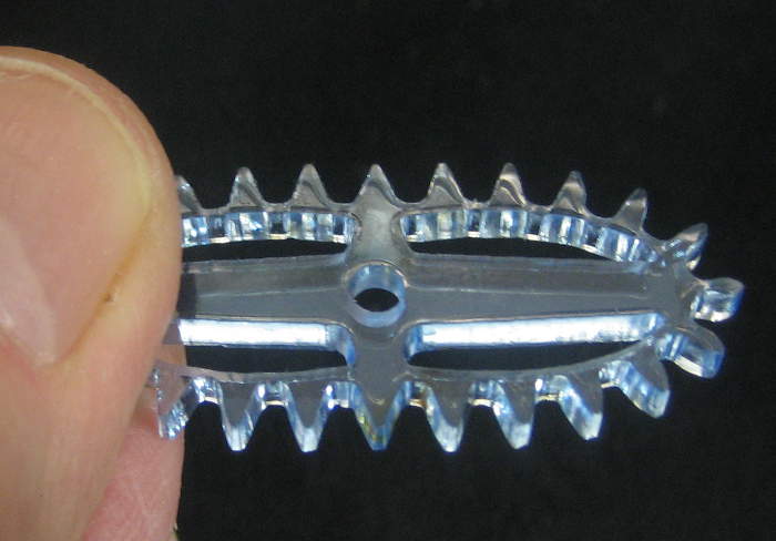
I wanted to have the laser cut center holes in 3mm acrylic gears that would provide just enough clearance to use 4-40 screws as pivots while allowing the gears to spin freely. I didn’t know exactly how much clearance that was or what the laser kerf in that plastic was, but since the kerf is significantly wider at the top 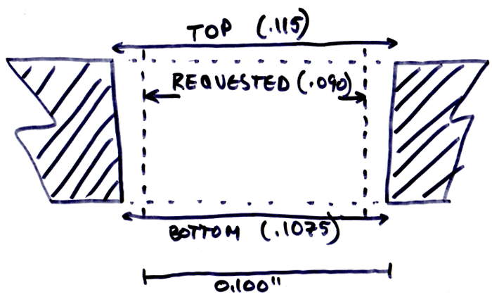 surface than the back surface of the cut, an experimental approach seemed suitable.
The nylon 4-40s I was using were about 0.105″ OD. After a couple of tries, I found that a 0.090″ hole in the svg produced a (conical) hole 0.115″ at the top and 0.107″ at the bottom. (180 LPM, 10% S, 100% P, 100% VC) I don’t think Retina Engrave tries to make up for the kerf like CAM for a milling machine (or EASEL) does. But whatever it does, those were the 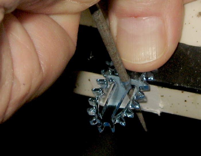 results. Those holes were sloppy for the screw at the top, and too tight for it at the bottom. (Yeah, should have fit. I don’t know.) This approach did let me do the final fitting with a round jeweler’s file for just the clearance feel I wanted. If I had to do a whole bunch I’d want a perfect drill bit, but for hand made onesy-twosies, this worked out very well.
So to produce that hole, I needed to provide a circle in the svg about 0.017″ smaller diameter than what I wanted. Another set of measurements showed needing 15 mils smaller. I think that represents the (whole) kerf (at the bottom surface).
As for the conical nature of the holes, these ended up about 80 mils smaller at the bottom. Other notes during the same set of experiments showed 60, but making those measurements was difficult, and probably not very accurate.
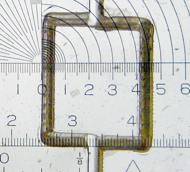 In another note in the kerf tests done for the gear hole, I noted that the kerf in acrylic was about .030″ (presumably at the top surface). In a separate cut for a finger joint box in 2mm acrylic, I measured the kerf using a graticule at about 0.5mm, or 20 mils at the top surface.
Searching for “kerf” in the FSE laser product forum provides some more points of reference.
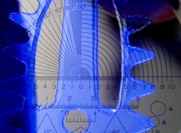 In addition to the actual kerf and the difference between the kerf at the top surface and bottom surface, there’s usually a small raised lip of presumably melted plastic above the top surface at cut lines. (Not much on the bottom.) On a straight line cut it seems to be about 0.4mm wide. There was a comment in the FSE forum about covering acrylic with a wet paper towel to reduce some effects like this.