
I’ve had trouble for a long time with my router (or occasionally my DSL modem) getting confused and breaking my lifeblood Internet connection. It can go months without happening, then happen multiple times in a day. If I’m home, it’s mostly an annoyance. But if we’re on vacation and depending on the house monitoring system to reassure us that all is well, a broken Internet connection is a real problem.
I’d considered spoofing an http session to log into the router and modem and soft-reset them, but that’s a hassle, and sometimes the router gets so messed up I couldn’t get into it. So with a year or two of thinking about it under my belt, two years ago I started actual construction of hardware to remotely power cycle both the modem and the router.

Corrected schematic
The outlet had to be normally live, and if the controlling PIC failed it had to continue to power the modem and router. A solid state relay let me do that by shorting out its LED with a 5V reed relay operated by an output pin of a PIC.
 I built that into a 4″ box with a short male pigtail and one duplex outlet for the two wall-warts that supplied the devices. It had another pigtail of low-voltage wire coming out to go to the PIC. It sat mounted on the wall that way, powering the network stuff for two years – with nothing connected to the control pigtail.
In the mean time, I built up a PIC node and wrote code so it would set an output pin high for 20 seconds when it heard a command. It had an LED on its output pin for testing and sat on the bench for a year that way. I even added code to the user interface of the main perl program to send it the necessary command, and had an RJ45 pigtail from the 485 network hanging right there ready to plug into the PIC node. I even passed on some good deals on routers to replace the flaky one because the flaky one would provide the best test environment for the reset system.
 Inspired by a couple of recent router hangs, I finally got around to the final small hardware steps of putting a diode across the output pin of the PIC (to protect it from any reverse spikes from the relay coil), putting a suitable connector on the control pigtail from the outlet box and plugging it all in. It worked! No surprise, but it felt good to finally have all the bits connected into something useful. You can see the controlled outlet box on the left, the PIC node at the bottom right, the wall wart that provides 12VDC on the cat-5 that implements the network, one of the “T” joints of the network, and the brown/white pair that carries the data back to the computer. The power strip with the 485 net power supply and the short lead to the router reset box is run from the main UPS. Who knows – I might even put things in housings some day 🙂
Of course that isn’t really very helpful. If the router hung, I could fix it from the computer keyboard rather than walking about 15 steps and power cycling the router. Woo hoo. It was designed to be more automatic than that, and now that the hardware was working, I couldn’t just let the software go for another year. I already had a continuous ping to my ISP running as part of the system, and now it could provide the info of when the router needed a swat. A couple of hacks to the ping program and the main perl program to hook them together, and I had an automated resetter! OK, and a little troubleshooting – like addressing the design flaw that the 50-seconds-of-no-ping-replies threshold that triggered a reset was shorter than the reboot time of the modem and router, providing an infinite power cycle loop the first time it tried to save the day. Oops.
But how would I know when it actually did save the day? The main perl program already has a fully functional mechanism to post what its sensors observe to the web site. And the new PIC node has its own address, event IDs, data structures, etc, so “it shouldn’t be very hard to add one more section to the web page” with history of recent automated resets.
After a lot of rediscovering how the system works (Why are there 5 elements in this structure? Can I use them? Why are there THREE php files to set the web page configuration? Why was I so dumb as to use all these similar 2 letter variables names? I should just be able to duplicate this section – it’s pretty much like the one I’m adding. Oh – except for that. And that… ) But the good news is that when it was actually printing timestamped entries for recent resets and I realized they were off by 2 hours (just like some other timestamped info) I finally got annoyed enough to dig into php enough to figure out how to set the timezone. Fixed two problems at once with that, and had the great pleasure of removing the embarrassing announcements that the timestamps were off!
With the web site update, a schematic (why is it to hard so add schematic symbols in Eagle?) and this post, I think this one is actually DONE!
UPDATE 6/1/13: The router resetter has been running for wow – 2 years? – now, and it’s been great. I don’t think I’ve been hassled by outage caused by my dumb router or modem since the resetter’s been in place. It reports to the home monitoring status page, and I see a reset maybe every week or two. This one looks like a total success!
Update 12/5/15: The dumb NVG589 modem/router/gateway device AT&T put in when we switched to Uverse VOIP has a built in backup battery (as is most appropriate for a modem supporting house telephones!). Unfortunately, this means my old power-cycle reboot trick won’t work any more. I haven’t quite been able to bring myself to pull the battery, even though the router is powered from the substantial house UPS. I looked at doing a reboot thru the modem’s user interface, but spoofing the password dialog got too messy. The failure today is making me rethink pulling the battery.
Somehow, I defeated the reset stuff when the NVG589 was installed. The home page still shows ping stats, but never reports restarts. (It should ~1000 lost pings this morning, and more with the second failure.) I took a quick look today, but haven’t been able to see how it works – or doesn’t work. I need to dig in some more to turn it back on so it will have a chance to help out when I pull the NVG589 battery. Ongoing…
(several hours later) OK – got it. The ping monitor – pingstat.pl – decides when the router needs to be reset, 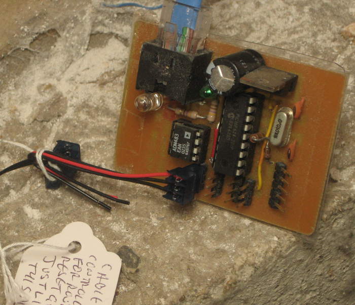 and when it does, creates empty file resetFlag. The main 485poll perl script checks for that file after every round of module polls, and if found, sends a command to the resetter module to cycle power to the controlled outlet. I’d unplugged the resetter module from the 485 net (so it’s been timing out every poll for the past year or 2 – ouch) because I didn’t want to disconnect the wire to the controlled outlet for fear of losing how it was connected, and didn’t want the outlet to be power cycled. I just put a dummy connector in showing how the real cable plugged in, tied it to the real cable, and attached a tag explaining that.
Then I plugged the resetter module back into the 485 net, and bless Microchip’s heart, it came right up and started responding to polls as evidenced in 485stdout! Then I touched 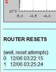 resetFlag, saw the 485poll script find it and get an ack from the resetter module. And a few minutes later saw that the reset info had propagated to the main monitor web page! Why there are 2 I don’t understand 🙁 .
In any event, the stage is set for removing the battery and letting the old ping failure detection try to reset the NVG589. Hmm – not quite. Since it often takes ~20 minutes for the gateway to boot and sync up, I probably need to crank up the dead time in pingstat.pl before it tries a subsequent reset to avoid the unpleasant reboot loop. Looks like the line there is
$resetTimeout=240; # don’t reset more often than this (sec)
Should be easy 🙂
Pingback: Home automation reporting system | Jim's Projects
Pingback: AT&T Uverse failures | Jim's Projects