Led Tester

I put a couple of minimalist LED testers together out of junk parts for the space.  9V snaps harvested from dead 9V batteries, old but not dead 9V batteries, some female headers and resistors.  The header and resistor are soldered directly to the connections on the snap and covered with hot melt glue.  A layer of white-out makes the background for the polarity labels.  These should be good to just have out on the table for circuit building or Arduino classes.  We might even have a few around and leave them on other hackerspaces’ benches as a little branded present!

Sorry for the poor picture.  Picturenaut failed me – I just couldn’t get nice HDR pictures like I did before.

Posted in Workshop 88 Stuff | 3 Comments

Chewed soaker feed hose

(This is the first of what will presumably be an ongoing series of small repairs and improvements around the house.  I’m not sure how to manage it:  individual posts per event?  One post for say watering system, one for sump pump, one for wiring, etc, with individual repairs as updates to those category posts?  And what about just documenting such systems?)

During a routine inspection of the landscape watering stuff, I found a geyser coming from an apparently chewed 3/8″ hole in a poly hose that feeds a series of per-plant soaker hoses on the Saylor side of the house.  The system has been in place for a couple of years, and I’d never seen anything like that.  After I patched it up with Gorilla tape (until I could get a repair coupling), I found another smaller spray from another apparently chewed spot on the same hose.  I taped that one up, too.  The tape did seem to hold fairly well, but I only observed it for a few tens of seconds.  But at least some plants will get more water than they would have until I can get some parts.

I guess I better do such inspections more often.  I also found the main hose feeding the rose garden sprinklers had popped apart and was soaking a few bushes while providing nothing to the others, and a similar smaller spray where a soaker hose connector had failed and come apart.  Since the watering happens very early in the morning, I don’t see stuff like that unless I go looking for it.  I guess the parts don’t last forever!

Update 7/25/11:  All fixed.  The challenge was finding a coupling to fit this hose.  There are an annoying number of similar but incompatible sizes of black poly hose.  I don’t think I even found any of this exact hose to try to match the size, but fortunately, I had discovered I could make an end cap with what might be 1/2″ CPVC pipe.  I had a piece of that and cut couplings for the 2 bad places.  A package of hose clamps and I was in business.  So it’s all done – until the next chewer attacks.

Update 9/3/11:  More hot weather – and more thirsty animals.  I can’t believe how much they chewed out this time!

I had some spare parts for this hose system and used a T that was pretty long and fit this hose.  The critter also chewed up the drip tap that connected the short 1/4″ soaker hose to the feed hose, so I poked that into the stub of hose closing off the other branch of the T.

Unfortunately, there was another chewed hole I missed.  The new connection also leaks pretty badly.

I wonder if I should just put out a bowl of water for the critters – presumably automatically refilled from the watering system.

Update 9/4/11:  OK, I pushed the leaky end of the feeder further into the T and put a “goof plug” into the other hole.  The leak at the edge of the T went away, but the plug didn’t work very well.

I kind of gave up and decided to see how long just wrapping it with Gorilla tape would last as a semi-permanent solution.  I dried the hose off well and washed the area with alcohol before applying the tape. Unfortunately, there was another branch tube coming out 3/4″ away from the failed plug.  That meant I either couldn’t get as much tape to that side of the plug hole as I wanted, or I’d have to cover both – and not get as much at either end as I’d like.  I chose the latter, and did one piece of tape – maybe 3 wraps – wrapped as tightly as I could centered over both holes, followed by a piece at each end.  Because I was taping over the thickness of the first wraps, the last 2 didn’t lie very flat, and I question whether they do any good at all.  (If it had been a single hole, it might have been improved if I put a hose clamp over the tape right where the hole was.  Maybe even a piece of the same tubing maybe an inch long over the tape and under the clamp to apply clamping over a little wider area.)  When I tested it, there was only a small dripping leak.  Not great.  I’ll watch it over time and see how it holds up.


Posted in Home Repair | 2 Comments

UPS battery monitor started!

My UPS is a big old sine wave clunker retired from work many years ago.  It works fine, but the only “management” info it provides is a dry contact closure when it’s on battery – not very useful to know how close to end of battery life we are during a power outage.

There’s been a project on the list for years to monitor the battery voltage of the two large deep-cycle marine batteries that power it.  Thanks to a donated Teensy, that project is starting to come to life.  Sorry PIC, but I could write this in 10 lines of C instead of battling through PIC assembler yet again.  I got the Teensyduino environment up with no problems.  Here’s the prototype that let me get started.

The monitor’s job is simple:  Measure battery voltage and spit it out serial once every few seconds.  Actually measuring the voltage range of interest is more challenging.  The battery runs ~28V fully charged, and the UPS probably cuts out when the battery drops to ~20V (not measured yet).  If I just put a divider across the 28V to bring it down to the 5V range of the Teensy, the 8 volt range of interest is only about 30% of the A/D range, so I’d lose considerable precision.

By dropping a pretty accurate say 20V from the positive side of the battery, I get a nice 8V which I can then scale to the 5V range of the Teensy.  I can use a negative voltage regulator upside down to do that.  There are a couple of calibration issues, including setting the regulator to a low enough voltage that its dropout voltage is accounted for.  Obviously the code needs 2 calibration constants:  An absolute offset representing the regulator voltage, and a scaling factor to account for dividing the 8V (or whatever) to its 5V A/D range.  That should be pretty easy.

(This approach came from expecting to use an 8-bit A/D in a PIC.  With the 10 bits in the AVR chip, I could probably afford to keep it simple and just do a divider across the whole 28V.  If I did that, the range of interest – 20-28V – would span ~30% of the 1023 count A/D range, giving me ~300 counts.  I guess I should be able to live with that.)

The Teensy’a serial output will go through an opto-isolated path to another normal PIC node on the 485 network.  The serial out bit should be able to drive the isolator’s LED without any trouble.  Since that PIC’s UART is busy talking RS485, it will have to do bit-bang serial on some other pin.  But the data rate is so low I could run that at 300 bits/sec or lower.  It should be able to handle that rate with no problems.  More to follow…

Posted in Home Automation | Leave a comment

AC supply for time lapse with Canon SD600

Since it seems likely I’ll end up doing more time lapse photography with CHDK and my little Canon SD600 it seemed appropriate to make a dedicated supply for it rather than hauling the unholy hack of a battery directly in parallel with my bench supply and a lot of clip leads described earlier.  (And then I can get my bench supply back on the bench!)

I was planning to use an LM317 adjustable regulator, but while rooting around in my regulator drawer, I found a TO-220 regulator with 3.85V hand-written in Sharpie.  It was otherwise unmarked, presumably from a “poly-pak” assortment of regulators, apparently tested by me many years ago.  A quick test showed it was really 3.85V, and putting an 8Ω resistor across it dropped it very little.  Sounds like a good replacement for a 3.7V battery!

I found a 12V 1A wall wart and tried it with the regulator and the camera.  Close, but no cigar.  It would turn the camera on, but immediately turn off.  Looks like I needed a little more voltage.  With a Shottky diode between the negative side of the supply and the nominal ground pin of the regulator, I saw 4.1V and the camera worked correctly.  The regulator got hot, but that was expected.  With the display off, the camera only drew ~50mA while idling.  With the display on, it was more like 150mA, and there was a 400-500mA peak when it took a picture.

So I put it all in a little aluminum box, using the box as a heat sink for the regulator.  Since the leads to the fake battery could have little more than bare wire at the end to fit through the little hole in the battery cover, the choices of output connector for the supply were a pigtail with alligator clips or binding posts.  Since there’s still chance of mishap with clips, I chose binding posts.  Not much inside.  You can see the knot/hot-melt strain relief.  It will get its inaugural run tomorrow trying to catch application of the last layer of blacktop to the street in front of the house.

Update 7/20/11: It worked fine and I got a nice capture of the blacktop laying.  With the display off, the box got warm, but only a little.  Success!

Posted in Li-ion camera battery, Time-lapse photography | 3 Comments

Home automation reporting system

This is a work in progress!

Overview

The system starts with several small “sensor nodes” that monitor things (like temperature) or control things (like sprinklers).  They’re connected via an RS-485 network at 56Kb/sec on Cat 5 cable.  That cable also provides 12V DC to power the nodes.

The other end of the 485 network is the main control or monitor machine.  Software running on this box polls the sensors , collects their data, and ftps updates to the web host.  Additional software there creates the page we see.

Software structure

There are three main components to the software:

  • Node-specific software in the sensor nodes (written in PIC assembler) that performs the node’s tasks and communicates over the RS-485 network.
  • The “poll” program running on the monitor machine at home (currently a Pogo) that polls all the sensors over the RS-485 network, collects their information, and ftps updates to datafile.csv on the web host every 5 minutes.  Other cooperating programs on that machine provide a user interface, monitor network connectivity, and more.
  • The “page display” software running on the web host which paints the main status page and creates the graphs (and text reports) from the data in datafile.csv displayed on that page.  It also has links to these Project Notes and other pages served by that GoDaddy-hosted web server.

Node software

As of 4/13, all the nodes are still running on PICs with code in assembler.  While I finally structured that code into some sort of skeleton with all the communication stuff plus some node-specific parts, it’s still not fun to work on, and I have to figure it out again each time I need a new node.  (And figure out how to run the programmer, and probably download a new version of the IDE…)  Some day I expect to get an Arduino (or some Atmel chip) based sensor node running so I can write in C.  An SHT15 temperature/humidity sensor that’s been sitting on the shelf for a year is a likely driver for that.  Some day.

Update 6/3/14:  I’m starting to try to run nodes on Arduinos (or the like).  First step is to reverse engineer the protocol.  Fortunately, there are fair comments, so it’s not like starting with a sniffer 🙂

The protocol is: [sync/header byte (‘U’)] [src addr byte] [dest addr byte] [opcode hi nibble; length lo nibble] [0 or more data bytes] [CRC lo byte] [CRC hi byte]

Master addr is 0.  Slaves are defined uniquely.  We can have up to 16 opcodes and length up to 16 bytes.  Found this in some source:

;------------ OPCODES -------------
#define    OCpoll        1
#define    OCretr        2
#define    OCrst         3
#define    OCgeterr      4
#define    OCdata        5
#define    OCdata.err    6
#define    OCack         7
#define    MAXOPCODE     7

“Received length” is at least 6.  What’s in the protocol length nibble is (num data bytes + 2 for CRC).  That’s always 4 less than “received length” (hdr, src, dest, op/len are not counted in the protocol length).

CRC is really just a 16 bit checksum at the moment.

6/5/14:  OK – got the Mega with a 75176 on a breadboard to send Quick Brown Fox to the USB-485 converter plugged into the Ubuntu Dell Mini 9 at 115200!  Used Mega since it has multiple serial ports.  Grounds between PC and Dell Mini 9 didn’t seem to be a problem.  Wrote up most of a basic message parser/validator.  Never sends out the 485 device.  Should echo parsed received messages when plugged into the real 485 net.  (And shouldn’t screw the network up!)  Basically a protocol aware (but content unaware) 485 net sniffer to see if it works, is fast enough, etc.  Currently stuck on parsing message boundaries.  I think timeout is essential as terminator.  Maybe?
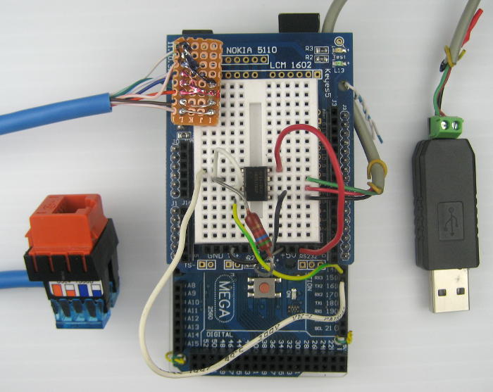
6/6/14:  Rs485OnMega1682
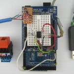
I made up a little breakout to 0.1″ pins for an RJ45 female with the standard 485 net Cat5 pinout.  Here it is on the Mega with a driver and the initial pair to a USB-485 adapter.  Very next step is to see if it can parse (read only!) live messages on the house network!

Later that day:  Wouldn’t read anything at all until I reversed the hard-wired data direction on the 75176 (from initial fox send tests).  Oops.  I would expect that always-on sender to mess up the network, but surprisingly, it didn’t seem to.  While the RJ45 breakout isn’t wired yet, you can see the direction pullup still connected to +5 in the pic above.

ParsedRcvdMsgs
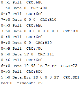
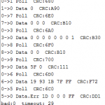
After a few tweaks, success!  While looking at the parsed messages, I found that the temp2 (addr 5) outside temp sensor seems to constantly respond with opcode 6, which I vaguely recall indicated first response after startup.  Looks like it is used for first reply after start as well as somehow to report errors.

The great setTimeout() on serial stuff inheriting from the Arduino 1.x Stream class made the code pretty clean.  I’m kind of depending on silence as a message delimiter.  Seems to me I had to put delays in maybe to allow for turnaround time in 485 adapters.  I put a pot on the Mega so I could play with the timeout, and found that with timeout of 29mS it works pretty consistently, but at 31 it misses some data (gets the polls, though).  At 34 it only gets polls.  That’s a very useful data point.  Since I’ll be managing data direction on the 75176/483 TTL/RS485 (422) driver, I can use any timeout I choose for receive parsing.  Let’s pick 10mS.

Guess I better add a 30mS delay before I respond to polls, though.  I should look back through the old node code to look for a delay like that.  (later) Found:

;-----------------------------------
; MAIN LOOP PROCESS RECEIVED MESSAGE
;-----------------------------------

rx
    call    tenms
    call    tenms
    call    tenms

;------------ process opcode--------

Next step:  (Read a sensor and) actually respond on the network!

Update 6/9/14:   Various bumps along the way, but I got code working on the Mega2560.  It decoded existing traffic on the live 485 net (yeah, the first connect was scary).  Then I added stuff for the DHT22 temp/humidity sensor, put code in to respond to a poll, and (with the new section in 485pollC.pl,)  it all seems to work!

Of course the target is a Tiny 4313 (since it has an actual serial port that has a chance of being close enough to speed (with a crystal or 8MHz ceramic resonator) to work at 57600.  First I took out the second serial port stuff and verified that it still worked on the Mega.  Then I tried to compile for a 4313.  (Using a boards.txt entry for “2313 hacked for 4313”.)  Unfortunately, the new Serial.setTimeout() and Serial.readBytes() the code depends on aren’t there in the Tiny4313 core.  Rats.  Rewriting the code without the timeout was very surprisingly hard.  Changing readBytes() to use read() was pretty easy.  And both sets of code were nicely localized.  Got the new version running on the Mega, and then stripped out the second serial port stuff again for another try to compile for 4313.

Got the dreaded i:/program files/arduino-1.0.5-old/hardware/tools/avr/bin/../lib/gcc/avr/4.3.2/../../../../avr/lib/avr25/crttn2313.o:(.init9+0x2): relocation truncated to fit: R_AVR_13_PCREL against symbol `exit’ defined in .fini9 section in i:/program files/arduino-1.0.5-old/hardware/tools/avr/bin/../lib/gcc/avr/4.3.2/avr25\libgcc.a(_exit.o) error.  Messed with stuff I’d tried before about importing bin directories from WinAVR 2009 and 2010 – usually getting an error like ‘can’t create process’.

Googled the error messages some more and found an Arduino 1.0.5 install package with WinARV 2010 tools embedded from Erwin Reid and installed it.  And now it compiles!  And that tool chain even actually knows about Tiny4313, so I don’t have to hack a 2313 entry for it!  The bad news is that the smallest I could get it was about 4380 bytes – too much for the 4313’s 4096 bytes of flash.  Tried the Adafruit DHT22 lib, but that was even bigger.  Tried turning off the float support by #defining DHT22_NO_FLOAT, but it didn’t help.  That extra couple hundred bytes is pretty much a show stopper for using a 4313.  Bummer.  Yeah, I suppose something without the DHT lib might fit.  Grumble.

I did recompile for a Duemilanove, and that works.  So I could make up a little shield for a Diavolino so I could  put something in the bedroom, (or I suppose, run off a breadboard shield).  That might buy some time until I decide to get some 328P SMT 32 pin TQFPs and make an intial 485 PCB with them.  Ugh.

Still to do is responding to other opcodes: Retry, Reset, GetErrs, and Data to control stuff.  But since it doesn’t have to fit in 4K, the extra code shouldn’t be a problem.

Update 6/26/19: Still working on using the first Arduino node.  Motivation is rising, as I have a DHT-22 sensor installed in a perfect location under the eave on the far side of the garage, with cable going to the relocated (currently PIC) node.  I have an Arduino node built, with code that mostly works to read the temp/humidity sensor.  But since it will also be the rain collector reader, it will need additional code (very likely interrupt driven), and new code in the poll program.  But when the code works, it should be a 5 minute job to swap the node out and bring it online.  Theoretically.

<more detail needed>

The “poll” program

Currently about 1740 lines of Perl running on a Pogo, this program is the main control of the system.  Current version is called 485pollB.pl 485pollD.pl  It talks through a USB-RS485 converter professionally mounted to the side of the Pogo, polling all nodes once/min over that serial network.  While the basic poll message is the same for each node (except of course address and checksum), each node replies with unique data.  The poll program has a separate callback for each sensor to decode and deal with its reply.  Each sensor also has several associated data structures to store current values, accumulated counts, error counts, etc.  Both the callback and data hashes are indexed by the sensor name – “sump”, “rain”, etc.

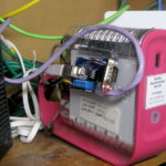
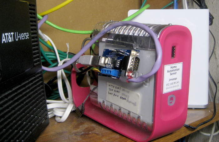
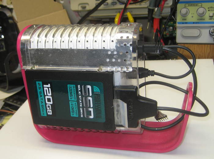
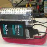
Update 6/26/19: The “professional” rubber band mounting has been upgraded to be supported by a sheet metal saddle, the other side of which supports a 120 GB SSD.  The latter should reduce the USB thumb drive “disk” failures.

For those nodes which can be controlled – primarily the sprinkler controller – there’s a simple external control mechanism.  A requirement was to be able to telnet ssh into the Pogo to control them, rather than accessing stdin/stdout on the poll program, which could only be done from the Pogo console.  So the poll program now listens for a USR1 signal in its main loop, reads a command file when it receives that signal, and sends control messages based on the file’s (one line ASCII) content.  A companion command line program (sendusr1) – which can be accessed by telnetting sshing in – provides a very simple user interface, writing the file and sending a signal when <cr> is pressed.  The prototypical application of this is logging in from the netbook a tablet from outside to control the sprinkler and watering systems while setting them up in the spring.

Update 6/8/14:  With an Arduino-based temp/humidity sensor almost working, I need to add a new block to the main poll program – which I haven’t done in a long time.  Working on 485pollC.pl, here’s what I had to do:

  • Under SET UP ALL KNOWN SENSORS, create new block for the new sensor.  Addr (here 11) must be unique.  I think the small ints for etypes, errtypes, retypes should be unique, though that’s not true for sprinkler and water.  It needs a unique string name (here th1 for 1st temp/humidity sensor), and a variable name for the function pointer, typically ${the name}ref.
    $sensors{th1} = [11,5,$th1ref];
    #$sentMsg{th1}=1;       # don’t do dead check on me
    $errs{th1}=[0,0,0];
    $data{th1} = [0,0,0,0,0,0];
    $etypes{th1}=24;
    $errtypes{th1}=25;
    $retypes{th1}=26;
    $etypes is critical – that’s what’s sent to web server.  Not sure if any others are used yet.
  • Create a # SPECIFIC PROCESSING FOR yoursensor TESTING block, typically by copying another block and doing significant modifications reflecting the intimate details of the data provided by the new sensor.  Here’s the block for th1:
    #—————————————
    # SPECIFIC PROCESSING FOR TEMP/HUMIDITY SENSOR 1
    # this is the most up to date one 6/9/14 – use as template for others
    $th1ref = sub {
    $len=@locchars;
    # 10=6 standard bytes plus 2 2-byte data values: temp, humidity
    lenOcChk(10);
    #—-Pull out specific data for this sensor—-
    $temp1lo=$locchars[4];
    $temp1hi=$locchars[5];
    $temp1=($temp1lo+256*$temp1hi)/10;
    $huml1lo=$locchars[6];
    $hum1hi=$locchars[7];
    $hum1=($hum1lo+256*$hum1hi)/10;#—– Announcement to 485stdout using data from above ——
    printf (“TH1 OK: $detStr $OCstr temp: %0.1f humid: %0.1f”,$temp1,$hum1);#——— LOG TH1 EVENTS using data from above ——–
    # event type, time, temp, humidity
    # ugh.  Gotta keep these two strings in sync!
    $logString=’$etypes{th1},$timesecs,$temp1,$hum1′;
    logit(“$etypes{th1},$timesecs,$temp1,$hum1”);
    }; # end th1 sub
    lenOcCheck() must reflect this sensor’s total byte count including data and CRC.  Up thru the printf() are sensor-specific, and should be pretty obvious.  The $logString/logit({args}) are the critical part.  There’s some other remnants in other sections, but this seems to be what’s needed.

Update 6/9/14:  OK – seems to work with the new Arduino slave node.

Update 6/17/14:  If I actually get temp/humidity info from a sensor or 2, I’d like to include tomorrow’s high temp (forecast) to make the WHF decision.  That means I need a way to have the poll program interact with other scripts on the monitoring host (like doing a wget and parsing info).  There might be other applications for interacting with other code running on the main processor, too – like modulating watering.  So I need a general mechanism for that interaction.  I suppose it could just be files, but that seems pretty crude.

<needs more…>

Software on the web host

The page is served by an http request to the top directory finding index.php.  That file paints the structure of the status page, including the top nav buttons and sections for each of the reports – rain, temperature, power, etc.  Index.php used to include graphs.php, which is where most of the work is done.  Graphs.php reads and parses datafile.csv, checks the date range, and creates the .pngs for the graphs.  But that took annoyingly long each time the page was called, so now the graphs are created right after new data is ftp’d up, by a wget on the Pogo to graphs.php.  There’s some more here on that home page speedup.

The actual graphing is done by a php package called jpgraph.  That’s pretty good, providing several graph styles, lots of control over appearance, auto scaling, etc.  That package failed with a php upgrade when I moved my GoDaddy hosting to a newer server in mid 2019.  Downgrading php (from 7.x to 5.4) allowed it to work again, but it took lots of hacks to keep from generating a multi-gigabyte error log.  Seems stable now (6/19).

Configuration of the status page is ugly.  It was originally accessible from the main page, but that was removed after bad guys did bad stuff.  <to be continued>

The home page got hacked by some damn Pakistani hackers in March of 2013, probably through some php back doors I foolishly left visible.  My bad.  I changed all the passwords, restored the original code, and removed all my back doors.  I think I also removed all the several back doors they put in to get back in.  Ugh.

Some day, I hope to implement the code on the host as some kind of round-robin database so I don’t have to manually trim the dumb ascii file every so often.  rrdtool is a likely candidate.  (That’s still a goal/hope as of 6/19).

Other software

Partly out of curiosity about how much of the time my DSL connection was up, and partly to make the system more robust by resetting the modem and router when there are problems, another Perl program on the monitor machine runs a continuous ping to the first router at my ISP every 5 seconds.  It keeps track of max, min and average round trip times (though they’re not displayed on the web page) as well as missed pings.  After a number of consecutive missed pings (currently 20), it sets a flag (touch ./resetFlag) to have the main poll program send a command to one of the sensor (here, controller) nodes to power cycle the modem and router.  There’s an additional delay after such a reset before it will try another reset.  I suppose I should import the details about it from this post to have them all in one place.  (More details below.)

That’s fine for detecting and fixing a failure resulting in not being able to access the Internet.  But the dumb router – even the new one – apparently gets confused after running for a while (weeks) and stops serving addresses via DHCP.  It seems to still pass traffic when in that confused state, so the Pogo, with its static IP address and others whose DHCP leases haven’t run out yet still work.  But other devices – like my phone or a recently awakened laptop that request addresses on the fly – suddenly don’t work.

Fortunately, when the router is “confused”, it also fails to respond to http requests for its admin screens.  That allows another pingish mechanism to detect confusion:  If a wget to the router fails, the router is (probably?) confused and deserves to be reset.  Code to do that started to be installed 12/16/11, but couldn’t actually trigger a reset.  Working on this is a slow process – I have to wait a couple of weeks until the next incident to do more testing after it’s been reset.

A downside is that the router wget could possibly trigger a reset while something useful was going on.  Might just have to live with that.

There have been so many router failures – almost all handled by the router resetter since mid 2017 – that I have a separate post here to record them.  I’m sure there have been some that the robot has fixed that we never even knew about.  Yay!

On the ping stuff:  There’s pingstat.pl, running as a separate process since ~2001.  It’s gotten fairly sophisticated, recording average, max, and min ping times as well as missed pings, and automatically adjusting a threshold above which ping times are flagged as extra late.  It can report 2 cycles of stats – about every 5 minutes and about once/hr.  It logs its exception findings to pingxfer.txt, and by touching sendit2 tells the main poll program to ftp that sparse ping stat file to pingstats.csv (which is not csv) on the web host.  Graphs.php handles it from there.

Hardware details

Typical sensor

The sensors are implemented on small PC boards with the PIC processor and 10MHz crystal, a voltage regulator, a TTL-RS422 driver chip, some LEDs, I/O connections as appropriate for the task at hand, and an RJ-45 jack to connect to the 485 network.  There are several versions, depending on what they needed to do.  Later versions changed the ICSP programming connector from 4

Sprinkler controller

pins to 5 to work with a knock-off PICkit 2 programmer I started using a few years ago.  The biggest sensor node controls the landscape watering, and has 8 relays and a larger PIC processor.  Some have opto-isolated inputs to connect to water sensors on the floor or other devices at dangerous potentials.  New types will be created as new needs arise.

I chose RS-485 for its noise-resistance for long runs.  The network extends to the detatched garage (for the rain sensor), so long runs are part of the requirement.  The 57.6 Kb/sec rate was a compromise between speed and reliability.  There isn’t a lot of data moving around (yet), so that speed is quite sufficient.  Using RJ-45 connectors and Cat 5 cable is dangerous in a place with Ethernet running on similar wiring.  All the 485 net cabling is blue, and I work hard to not use that color for ethernet.

Since the half-duplex RS-485 uses only one pair (and a reference ground), I use the Cat5CablePinout
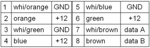
other 3 pairs in the cable to provide unregulated 12V DC to power the nodes and provide the ground reference.  Here’s the pinout:


Updates and bug fixes

7/8/11: I made a minor fix to the software on the web host that serves the main status page, and realized I didn’t have any place to record details of that (kind of ugly) software.  This is the first entry in a sort of change log, and has provided me the opportunity to put all the details of the system in one place.

Today’s fix was simple, but the background is a little convoluted.  I wanted to get rid of a harmless but ugly error message that occurred when the page display stuff tried to pull router reset events out of the main datafile.csv if there were no events there.  It wasn’t a problem before because there was always at least one “event”.  That event was not an actual router reset, but a startup header line that is part of trying to make the data in datafile.csv be sort of self-describing by starting out with a pair of lines – one data, the other field descriptions.  The poll program at home (now on the Pogo) posts one such pair of lines for each sensor each time the poll program restarts.

Unfortunately, that first-time-only line was also interpreted as a router reset, so the web page incorrectly reported a router reset each time the poll sofware was restarted.  No problem – I can fix that!  Not wanting to disrupt the (as yet unused) self-describing data mechanism by blocking that one entry, I hacked the code (in the poll software) for that one sensor’s handler to modify its initial data description entry (prepending a “#”) so it would not be recognized by the parser in the page display software.  That worked to get rid of the bogus router reset report, but created the situation that there were often no entries at all for that data type.  Thus when the page display iterated through it to report all the resets, the iteration failed – and thus the ugly error message.

So I just added a check to make sure there were events before I looped through them.  All fixed.  But as long as I’m making an entry for the web site software, I suppose I should put some info about it.  I guess this will evolve into the migration of the little “Home Automation” page to this more proper home.

7/22/11: Main perl code crashed yesterday trying to send me a text that it timed out a sensor 5 times.  Unfortunately, since when I ported it to the Pogo I couldn’t find SendMail.pm (NOT Sendmail.pm!) I’d ripped out the sendSMS() function, so when it tried to use it it crashed.  Found SendMail.pm, copied it over, tested it and put it back into the main code.  Also honored a note that the sensor timeout alert needed some kind of reset.  Added a walk through all sensors to clear timeout count and clean %sentMsg as an overloaded feature of the “A” turn on alerts control.

The reason the main poll program couldn’t talk to the sensors was that somehow the serial port wasn’t working.  It’s a USB-485 adapter, and when I unplugged it and plugged it back in it started working.  (Probably restarted the main program, too.)  No way to check for that yet, but I probably should.  I tried restarting the perl program remotely, but that didn’t help.  I think if I’d rebooted remotely it would have fixed it.

Update 7/28/11:  The towels that live on the floor by the below-grade family room door to soak up rain leakage were found very wet and smelly yesterday.  We don’t get water there much any more, and didn’t check them after the recent big rains.  If the floor water/moisture sensors had been in place, we would have been alerted.  It’s time to bump up the priority of getting those sensors in place.

The 3 parts required to do that are the actual floor water sensors, PIC nodes with opto-isolated inputs to keep the 485 net from getting ground-referenced when the floor is wet/flooded, and the software to run them.

I haven’t touched the code in a long time, so I guess I better attack that.  I just downloaded the latest MPLAB IDE from Microchip, and I’ll use this opportunity to reacquaint myself with the structure of the PIC code and document it here, filling in that very lonely Node software heading above.

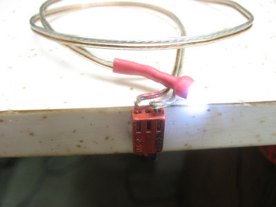
I played with water sensor boards a while back.  The basic interlocking fingers is sound.  An early version had the opto isolator on the sensor board.  Wrong!  That still puts wires directly connected to the 485 net on the ground in the water!  The good board has nothing but real estate for water to provide some conductivity to turn on a transistor.  Isolators are safely up on the PIC node.  Looks like I laid it out for various transistor lead layouts.

I’ve had some boards with 3 channels of opto isoloation for a while now, and even have one all made up.  That one will probably be the first production water sensor.  The isolated water sensors need to turn on the LED in the opto, so they need power.  There’s leads for a small battery pack – 2xAAA? – on the isolated side for that.  I’ll probably spend 2 channels for 2 water sensors, leaving the last for serial from the UPS battery monitor running on a Teensy.

Update 12/5/15:  After a router failure, I looked at the home page and saw old data and some php warning messages.  Apparently, config.php had gotten corrupted.  I hacked the main index.php to remove the option to modify the config file to turn on/off power outage details in hopes of avoiding future corruption.  Unfortunately/insecurely, if you clicked the ‘submit’ button near the display/hide details button, you can see the POST URL to config.php.  Anybody seeing that could try to inject garbage or worse.  By removing that option, I hope to close that door.  I changed it to a link to a separate page with the stats, so the info is still available.  I think this is a good change.

Update 9/2/18: The Godaddy hosting file datafile.csv seemed to need to be truncated too frequently.  I verified that it was still being restarted (with a “STARTED POLL APP” line) every 24 hours, but noticed the sump and power durations each had ~10 bytes of extraneous decimal data for every log line.  I changed these 2 lines in 485pollD.pl:

> #$dur=(256*$locchars[6]+$locchars[5])/5;
> $dur=int((256*$locchars[6]+$locchars[5])/5+0.1);
> #$Pdur=(256*$locchars[10]+$locchars[9])/5;
> $Pdur=int((256*$locchars[10]+$locchars[9])/5+0.1);

I think this lost the last 1/5 sec resolution, but saving ~24 bytes out of each ~116 byte log sequence seemed worth it.  Here’s old and new:

3,815,0,0,0,5004,15805.8000000007,0,0,1,10,7500.20000000001
15,815,1
11,816,32,77
7,814,79.7,82.4
5,814,0,3432
—–
3,65,1,3,0,1,3,0,0,1,0,0
15,65,0
11,66,32,77.9
7,126,79.7,81.5
5,127,0,0

I need to keep an eye on it to make sure that didn’t break anything.
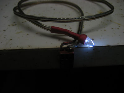
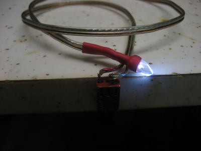
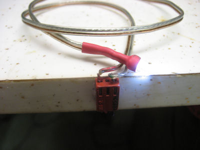
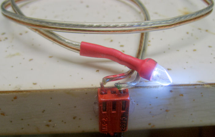
Posted in Home Automation | Leave a comment

HDR lets me photograph LEDs!

After I suffered a couple of the standard dismal failures anyone trying to photograph lit LEDs encounters, Google quickly provided the relevant buzz term: High Dynamic Range.  Initial browsing showed lots of pretty pictures, but to the inexperienced eye they failed to communicate the real message:  It is nearly impossible to actually take these pictures without special techniques. But after I played with it a little I understood how much these techniques could improve technical photos I wanted to take.

I don’t understand much (anything!?) about how the software merges the multiple bracketed exposures, using the “right” parts of each to produce a result that approximates what our wonderfully HDR eyes see, but by feeding a couple of exposures to freeware picturenaut and clicking a couple of buttons, I got dramatically better images than any single exposure could provide.

Here’s one example.  I took 5 exposures, one stop apart.  (Oops – am I showing my age?  I suppose I should say “one EV apart”.)  The nice picture at the end is the result.

All I did was “Generate HDR Image”, add files, enter the bias (since I wasn’t using a bracketing feature on the camera to provide that info in the EXIF data), and click OK, keeping all the defaults.  Then I used “Dynamic compression” in “bilateral” mode.  There are lots more knobs to turn, but even the defaults produce impressive results.

I’m glad to have this new tool in my arsenal.  I even made a Paypal donation.  Putting a button for that on a freeware site is a great idea.

Posted in HDR | Leave a comment

Skinny LED flashlight

I needed to see who was connected to what in the amplifier board of the Hilton repair project, but the traces were on the bottom of the circuit board.  I tried shining a flashlight between the board and the surface under it and that sort of worked, but I needed something  better and more flexible.  A skinny light on the end of a wire sounded about right.

I crudely ground the case of a high-brightness white LED to defeat the very efficient lens that pushes most of the light out a narrow cone at the end of the LED.  That made the light much more diffuse – just what I needed.  Then I soldered it to maybe 18″ of speaker wire and protected the joints with heat shrink so they couldn’t get in trouble if they bumped into something conductive.  I didn’t bother with a resistor, since an LED tester (with a resistor) lives on the front edge of my bench.

When I slipped the LED under the circuit board, I could see the traces in any area quite clearly.  Success!

[For anyone who has ever tried to photograph LEDs, you’ll know that it is nearly impossible to take the picture of the LED above. That picture is the first result of starting to play with High Dynamic Range (HDR) photographic tools.  Here are some of my HDR experiments.]

Posted in HDR, Hilton repair | 1 Comment

LED tester

One of the very useful tools that has earned a permanent installation on my bench is an LED tester.  It’s just an old 9V battery, a 560Ω resistor and a socket I can slip LED leads into.

The battery was past the end of its useful life for a 9V application, but at 6 or 7 volts still fine to light an LED.  With that voltage and resistor, it’s safe for most any color of LED (different forward voltages), but still allows enough current to light it nicely.

Since the battery doesn’t have to be replaced very often (the one in the picture has 1/91 scribbled on it!) I just hot-melt glued it under the bench far enough back for the wires to not hang down.  (I pried it off just for this picture.  Can you tell?)  The flat socket (also hot-melted on) is never in the way, but always available.  Highly recommended.

[The picture above with the lighted LED is almost impossible to take.  It’s the result of some HDR techniques I’m just starting to play with.]

Posted in Electronics workbench revamp, HDR | Leave a comment

Hilton repair

I took in an old non-working Hilton 75 square dance caller’s turntable/amp of Ray’s to see if I could fix it.  The first time I tried to work on it was before I cleaned a space on the bench, so it’s spread out on the family room floor.  Thankfully, Hilton has made a schematic available.  Without that I wouldn’t have even tried.  It wasn’t obvious how it worked from the schematic, but some googling of the transistors it used found a DIY article from Popular Electronics Feb 1967 on building the “Brute 70” hi-fi amp.  (Tweak the URL to get subsequent pages.)  With a couple of minor component value changes, this was exactly the amp in the (nominally 75W) Hilton!  And even better – the article went into the design, how it worked, and how to do initial calibration on it.  Can’t ask for much more than that!

I finally shoveled off the bench enough to have a decent place to work on it.  I narrowed the problem down to the power amp board.  The design is pretty modular in that the only connections to that board are power supplies, audio in (from a mixer/preamp that still works) and output to speakers.  Initially it was almost completely non-functional.  I could hear just the highest excursions of the audio waveform as little more than pops from the speaker.  It was alive, but *way* out of whack.  Injecting a little DC or paralleling a pot with a cleverly chosen resistor moved the bias point so it put out recognizable, badly distorted audio – but considerably better than how it started.  But with no obviously failed parts, troubleshooting was a challenge.

To make it more exciting, I now need this unit as a backup system for a square dance weekend July 8-10 (next Friday!).  And to make it even more exciting, I hit something with a meter probe, heard a loud pop (from the speaker) and now it’s completely dead.  The -43V supply is now at ~-21V.  (The +43V supply is still at +43V.)  My current dilemma is how to approach the troubleshooting/repair.  A check on the transistor specs shows that they’re good for 80V, which is higher than anything I have in my junk box.  (I do have replacements for the 2 output power transistors.)  I have a couple of options:

a)  Order all new transistors and see what happens.  There are NTE cross refs to all, though Fry’s doesn’t stock them.  But at least then I’d have 80V transistors.  Best case is that one of the trannys was weak/bad before, and this fixes what I blew out plus what was bad and it works fine.  Murphy is betting against that one…

b)  Plug it into a Variac and crank it down so the power supplies are maybe +/- 20V (they’re not regulated).  Then swap at least the small transistors for garden variety ones from my stock and see if I can get it basically working (obviously at lower power).  If I can, and if I can get proper replacements in time, it would probably work.  If I can’t get it to work, either there’s some other component bad or the rather sophisticated circuit depends on specific characteristics of the RCA transistor set it was designed around.  Next step would be unclear.

c)  Give up on the amp as it is.  Newark has a single audio power amp IC (TDA7293) rated at 100W and power supplies up to +/- 50V (abs max is +/- 60V).  There’s even a little PCB layout for it.  Make a PCB – which would even let me use the existing edge connector.  And of course hack it so the chip bolts to the existing heat sink.  It’s sort of pushing things to replace the amp with something completely foreign, but it didn’t work in the first place, and it looks like I’m completely within spec for the new part.  It should work fine…

d)  Go to Fry’s and try to find some NTE parts (since that’s all they carry)  that are good for 80V and see if those work.  (Radio Shack still has a few transistors, but none over ~40V.)  Like option b), this is based on the vague hope that the original design that used 6 different transistors in a 7-transistor circuit was just some guy at RCA trying to see how many different RCA parts he could get into a reference design, rather than that it actually depends on some weird characteristics of those parts.  (It uses RCA 40406, 40407, 40408, 40409, 40410, and two 40411s.)  My gut says subject to obvious stuff like polarity and working voltages/power ratings, it would pretty much work (probably even sound decent) with other general purpose transistors.  But it doesn’t say it very loudly, or with very much conviction.  What to do?

I’ve ordered the NTE parts and the amplifier IC, but they won’t be here ’til next week.  I’m too anxious to make some kind of progress to just wait around ’til the parts arrive and hope I can get something to work in the last day or 2 before it’s needed.  Do I waste an hour and a half trying to find high voltage parts at Fry’s?

Update 7/1/11: Agreeing with the recommendations of a guy at work and a guy at W88, I’m putting all my energy (for this project) into plan c) – replace the whole amp with an IC.  I’ve started the PCB design.  The board layout in the datasheet turns out to not be very useful, so I’ve started from scratch, including laying out fingers on 0.156″ centers to fit the existing PCB edge connector.  I’ll play with the original board at my leisure after the dance weekend deadline is past.

While I was still exploring the original amp, I needed to see the wiring to know which end of which component I was looking at.  I made an LED-on-a-wire light snake I could slide under the PCB and see the traces.  It worked out well enough that it will probably get a permanent home on the bench.


Update 7/5/11: Got the PCB laid out and etched.  No major problems.  I tied the “mute” line high, and am hoping there won’t be objectionable pops with it’s turned on.  But just in case I brought the mute line out to where I can get to it if I have to.  This is the first board I’ve done with an updated setup for etching with cupric chloride.  More on that in another post.

It’s a hybrid with some SMT parts on the foil side and some thru-hole parts on the other side.  I invested some time in improving my Eagle skills, including a valuable semi-automatic fill mechanism.  I’m getting faster at making packages for custom parts, and am learning which layers to use for what.  I guess Eagle is mostly a friend now.

There’s some cutting of this board blank to make the connector fingers fit into the Hilton edge connector.  Still waiting for some parts, including the main IC.  But I should be ready to put those in when they arrive – I hope Wednesday, possibly Thursday.  If it’s Friday, that’s awful tight.  I should be able to deal with most of the stuff like mechanical mounting before the parts come in.  More to follow…

Update 7/6/11: The new amplifier is coming along.  I cut the board back and slotted it so it fits the connector.  I got dimensions for the IC, mocked it up, measured things, figured how to mount it and made sure everything would fit.  While bolting the 15-pin IC to the heat sink would provide a sufficient mounting for the PCB, I set up an additional mounting bracket for it.  Nothing is  soldered in yet.   Now we’re mostly waiting for parts from Newark/Element14.  Old board is on left, new (smaller!) one on right.  You can see the connector in the lower right on both.

One remaining open issue is whether to dig out the gold plating stuff I got for some other project and plate the edge connector for better long term reliability.  Two more immediate concerns were thermal related:  There’s a thermal cutout wired (soldered) in series with AC power to the unit that was riveted to a part of the heat sink on the board to be removed; and since the tab of the IC is internally connected to V-, it would have to be insulated from the main heat sink (which is  electrically connected to the chassis).

You can see the cutout between the power transistors on the old board.  While the IC has internal thermal shutdown, it seemed a shame to remove the existing cutout.  I found a nice home for it on an aluminum bracket I made to clamp the IC to the heat sink – a fine solution, though there’s zero science comparing its temperature trigger to when the IC is “too hot”.  It’s better than nothing – unless it cuts out before the IC would be in trouble and does an inappropriate shutdown while the amp is in use!

The first thing that came to mind for a thin, heat-conductive electrical insulator to put between the IC and the heat sink was mica.  Does anybody still use that?  I thought strongly that I had some, but couldn’t find it and couldn’t think where to look.  Would I have to try to disassemble capacitors to try to find scraps of it?  As I googled it, I found the clue I needed:  a picture of an insulator for under a TO-3 power transistor!  I looked in the old power transistor drawer, and sure enough, there was a stash of mica TO-3 insulators, along with a couple of insulators of other materials.  Exactly what I remembered, and they’re plenty big enough to cover the heat-transfer tab on the IC.  I have lots of thermal grease, so I’m all set.  If the parts come.

Update 7/7/11: It’s done!  All problems resolved, tested, cleaned up and packaged, ready to go!  Oh yeah – one part left over – the old power amplifier board.

Parts came today, and board stuffing went pretty smoothly.  (OK, I put one electrolytic cap in backwards and it hummed a lot.  Rats.  You’d think I wouldn’t make freshman mistakes like that any more.)  Here’s both sides of the board and installed in the chassis:

The most interesting mechanical challenge was clamping the IC to the heat sink.  I made an aluminum bracket that used 2 threaded holes that used to clamp the power transistor heat sink to the main heat sink.  But it needed to clamp both the plastic body and the top of the tab.  The tab is set back 1/8″ from the body, so I made a wooden spacer to fill it in.  (Of course I couldn’t use metal since the tab must be electrically insulated from the heat sink, so also from the bracket.)

To insulate the back of the tab, I cut down one of the mica TO-3 insulators I found.  Thermal grease on both sides and it was good.  (Well at least on the third try.  Apparently when I put it back together after replacing the reversed electrolytic, the insulator fell off.  The back of the IC tab was all full of silicone thermal grease, so I was staying as far away from it as I could.  I guess I assumed the insulator would have stayed stuck in all that goo.  Wrong.  More hum – but now the power supply voltages were way out of whack.  Found the insulator, disassembled and reassembled again – this time with the insulator in place again.  Much better.  Dumb.  It’s that whole assume thing…)

The unexpected electrical challenge was that while it worked and even sounded OK, there was still quite audible hum.  The +/- power supply voltages were right on, so I finally put a scope on them.  Huge ripple on the + supply!  Thankfully, Hilton put the rectifiers on a nice plug-in board, so replacing the 2 diodes that were blown was easy.  That quieted it down quite a bit 🙂  I suppose the reversed cap or the oops with the missing IC insulator might have had something to do with it 🙁  It’s not as hum-free as I would have liked, but acceptable.

I tested it with audio from a good MP3 player.  Fortunately, the Hilton schematics made it obvious where I could plug audio in.  Surprisingly, it was exactly in parallel with the phono cartridge.  That meant  the RIAA equalization was applied to the nice flat music I was putting in.  That equalization is designed to reduce scratch/hiss, so what’s pressed into the vinyl has treble pre-emphasis, and that’s taken out in the phono preamp input in the mixer.  Sure enough, I had to crank the bass down and the treble up to get the music to sound reasonable.  But the Hilton’s potent music bass and treble controls let me do that.

I also ran music into the microphone input, just to make sure that worked.  Wow – I had to crank the voice treble all the way down to make the music sound at all decent.  But it worked, so it looks like both the voice and music channels are OK.  Rats:  I forgot to test the remote music volume control Hilton mics always have.  I think it’s just an isolated 20K pot, so I could have done it.  But it’s part of the preamp/mixer, which didn’t seem to have any problems, so it probably works.  (Such an ugly word.  Ugh.)

I cranked it up ’til I was afraid I’d blow out the substantial speakers I was using, and let it run for 10 or 15 minutes.  The heat sink got very hot, but neither the IC’s thermal shutdown nor the Hilton’s thermal cutout (which I mounted on the aluminum clamp bracket) triggered, and there was one part of the heat sink not even mounted yet, so it seems OK.  The chip has a clipping detector, and I laid out an LED on the board for it, just for testing.  (It’s not visible when the unit is all together.)  I did see it flicker a little when it was cranked up to the point of distorting a bit, but I was unwilling to run it that loud for more than a few seconds.

Eventually, all the too-long screws got cut down, the missing spacer found, everything tightened up for the last time and I could put it together.  (It’s amazing how messed up the bench got from working on just one project!)  Oh yeah, it’s a turntable – better check that out too.  I found an old square dance 45 and put it on.  Seemed to work fine.  But when I took the record off, the back side was covered with black crud from the decomposing ancient foam turntable pad.  That’s really unacceptable, so I scraped off the old pad, found some not-yet-decomposing foam rubber and cut a new one.  It’s a little thicker than the old one, but should be OK.  And it doesn’t leave junk on the records.

Of course I tested it some more with it in final assembled form, and everything is still good.  Because I didn’t get the parts yesterday, I invoked Plan B and arranged for another system for backup for the weekend.  I’ll bring this one along as a second backup, though I’m sure it won’t be needed.

But it’s not quite time to return it to Ray.  I have all the replacement transistors, so I’ll probably take another crack at the original amplifier board after the smoke clears from the weekend.  I wonder what challenges that will bring!

Posted in Hilton repair | Tagged , | 9 Comments

Scrolling LED Display

Russ’ post of a link to a one-wire serial-parallel latch to drive 16 LEDs from one pin on a micro reminded me I had an old LED display we might rebuild into something useful.  It was from work maybe 25 years ago (!?), given away presumably because it didn’t work very well because the 1:64 multiplexing didn’t let the LEDs get very bright.

It’s 7 x 64 red LEDs in a nice 5.5″x5″x35.5″ laminate over pressboard case with a smoked plastic faceplace (which, while cool, makes LED brightness even more of a problem).  It has four 74154 4-16 decoders to cover the 64 columns plus a gate to select one of those four decoders.  The 7 row connections are brought out, as well as 6 lines to select columns.  There will be lots of rewiring to bring all 448 of those LEDs out to latches, but it might be a fun project.  I’ve offered to make a PCB for the latches and donate the display to the space if folks would like to build it into something useful (or even use it as is for an interesting Arduino exercise).

Update 7/26/11:  Our “Hack a Scrolling LED Display” get-together was a great success.  I’d played with it enough beforehand to be confident we wouldn’t have to send people home after discovering that it didn’t work at all, but the group successfully reverse-engineered much of it, did some initial testing, hooked it up to power, made a connector so it would be easier to plug into an Arduino, and wrote code to drive the column-select electronics.

We could only get half the display working – there may be a hardware problem with at least the 3rd from the left SN74154 column decoder.  All the LEDs seem to work, although brightness isn’t as uniform as one might hope for.

All together we had 8 people working on/observing the display, and Fredo stopped in as well.  Edgar brought friend Alex from Fermi, and Andrew seems to have gotten 3 high school students to come.  New member Dan Gray came in to join us as well, adding some seasoned expertise to both the hardware and software sides.  Edgar and Alex handled the  hardware, dealing with the power supply and soldering up a header to connect/disconnect the display from the Arduino easily.  Andrew headed up the coding side using a freshly installed Arduino IDE on Renae’s graciously loaned laptop, with help from Dan and conversations with the students as they watched.  I wandered around, consulting, trying to ask questions to keep things moving, touching as little as possible.  I did provide a little troubleshooting when the column select electronics didn’t seem to be working.  We got past a miscommunication that led to reversed power supply connections to the TTL chips.  Thankfully, the chips survived and went on to select columns as designed after we got the power polarity correct.

The only casualty was Andrew’s Arduino, which no longer talks to avrdude.  He’s going to try reloading the bootloader.  Swapping the ATMega should be another troubleshooting step.  Sorry for the inconvenience, Andrew!

I left the display running a full-column vertical bar scanning back and forth over the half the display that works.  Shame on me for not getting any pictures of the group working or at least the scanning display.

There’s more to be done.  In particular, we didn’t do any control of the row pins.  I’d even made up a little header with per-row resistors, but we didn’t get quite far enough before folks had to go home.  I don’t know whether we should bother trying to troubleshoot the other column select hardware, since it will all be ripped out for the final configuration.  Next step might be breadboarding a column or 2 worth of latches, and perhaps starting the per-column latch board design.

All in all it was good fun and exactly the kind of stuff that should be going on at a hackerspace!

Update 8/26/11:  The second get-together yesterday was very good.  Since a critical step is designing the per-column latch boards, I went over some Eagle basics.  From a comment on the Meetup page:

Very successful. We got thru the very basics of schematic capture, PCB layout, and the critical creation of new parts in Eagle. Jim H got the display disassembled so we could work on it. We measured the LED spacing and discussed pad size to solder the LED leads to. Dan created an Eagle “package” with the pad layout for the LEDs and started a board layout using it. We did some informal LED current v objective brightness tests and confirmed our expectations that it should look fine at ~15mA. Great fun!

I’ve ordered the latches – 74AC542s – a closeout at Jameco for $0.15 each!  I suggested a tweak to the physical board layout to reduce the amount of board needed.  John Greusel reported good results with toner transfer and a heat press he got on Ebay.  I sent him a note asking if he’d like to help with manufacturing the 64 boards we need.  The topic of reflow or hotpad and hot air gun as a good mass production approach was also brought up.  Open issue.

Update 2/10/12:  I made up the other 4 latch boards at the W88 meeting last night, so we almost have the initial 6 boards.  (I failed to put the per-LED resistors on the board used for the very first reflow test – I’ll have to do those by hand.)  I cut the boards apart, solder-pasted them, laid out the parts, and reflowed all 4 at once on the hotplate at the meeting.  Came out pretty well.

When cutting the boards apart, the long (vertical in these pics) cuts are made with a hacksaw with the board in a vise (before the resistors are soldered on!).  That inside cut was made by scoring with a cutoff wheel in a Dremel, breaking the boards apart by hand, then cleaning up the edges.  I really need to be careful with the cutoff wheel, as there’s almost no clearance at the ends.  I completely cut through one trace, almost completely cut another, and nicked a third.  Not too hard to repair, but that was pretty sloppy.

Wiring, logic

Since the 74154s outputs are active low, the original design must have had the wire-wrapped common for each column connected to all the LED cathodes.  We’ll use those wires, but hard wire them to ground.

We have to put positive on the other LED lead (anode) through the latch boards.  Obviously we’ll need to rip out all the long wire wraps joining all those anodes.  The latches are non-inverting, so the code will have to put out a high to light an LED.

The clock on the 75AC574 latches input data on a low-to-high transition.  That means the code will have to:
– write the address of a column on the 6 address lines (74154 output goes low)
– set up data for that column
– write the
next address on the address lines (our clock goes high and latches)
– set up data for next column …
Since the latches are not transparent, changes to the data while the clock is either low or high will not get written to the outputs, so I think this approach should work.  But the test is the test. 🙂

Since an Arduino output pin probably can’t drive 64 latch inputs, we’ll need a few (4?) octal buffers with the Arduino driving those and each one driving some (16?) latches.  Nothing is even started for that yet (but we don’t have 64 latches yet, so …)

Resistors

I’m not sure how to manage the series resistors.  All the boards made up so far (4 of the initial 6) have all 220Ω resistors.  If we want quite consistent brightness, we may have to tweak (some) individual resistor values.  But to avoid the unpleasant task of unsoldering a board we just soldered in, we should do the resistor tweaks before soldering the board on.  But we don’t know what tweaks (if any) are needed at that point.  We may want a test jig to check the brightnesses of all of this column’s LEDs.

Since the voltage drop in the latch’s output circuit matters, maybe we should make up a latch board that starts up with all outputs high (some RC on the clock, maybe), with all 220Ω resistors, and with some kind of sockets (perhaps on a pigtail) we could plug briefly on to the column of LEDs we’re about to solder a latch to.  Ideal would be to use the code and the existing wiring to light all LEDs in the previous column for comparison.

It gets stickier from there.  If all the LEDs look good, fine.  If one (or more) looks bad, how do we know what resistor value(s) to use?  We’ll probably have only a small range of values to choose from – maybe 180, 200, 220, 270?  Switchable resistors of all values for each LED would be a real hassle.  Since I’m guessing low brightness will be the most common problem, I suppose we could have something like a header with the 2 sides of each resistor brought out.  We could put a pot (just one end and slider) on a female pigtail, plug it across the existing 220Ω, and adjust for matched brightness.  Given its value in parallel with 220, we could compute the ideal value and so make a good guess about which available value would be best.

When we get all the 74154s/columns working, we could step through each column with an Arduino driving all LEDS on (like the cylon code we have now, but manual increment/decrement) and look carefully at them, noting exactly which ones were questionable.  That’s certainly the easiest first step, and maybe sufficient for spotting those (I hope!) few LEDs we’ll need to worry about.

Posted in Scrolling LED, Workshop 88 Stuff | 1 Comment