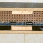
 Russ’ post of a link to a one-wire serial-parallel latch to drive 16 LEDs from one pin on a micro reminded me I had an old LED display we might rebuild into something useful. It was from work maybe 25 years ago (!?), given away presumably because it didn’t work very well because the 1:64 multiplexing didn’t let the LEDs get very bright.
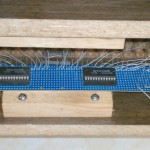
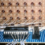 It’s 7 x 64 red LEDs in a nice 5.5″x5″x35.5″ laminate over pressboard case with a smoked plastic faceplace (which, while cool, makes LED brightness even more of a problem). It has four 74154 4-16 decoders to cover the 64 columns plus a gate to select one of those four decoders. The 7 row connections are brought out, as well as 6 lines to select columns. There will be lots of rewiring to bring all 448 of those LEDs out to latches, but it might be a fun project. I’ve offered to make a PCB for the latches and donate the display to the space if folks would like to build it into something useful (or even use it as is for an interesting Arduino exercise).
Update 7/26/11: Our “Hack a Scrolling LED Display” get-together was a great success. I’d played with it enough beforehand to be confident we wouldn’t have to send people home after discovering that it didn’t work at all, but the group successfully reverse-engineered much of it, did some initial testing, hooked it up to power, made a connector so it would be easier to plug into an Arduino, and wrote code to drive the column-select electronics.
We could only get half the display working – there may be a hardware problem with at least the 3rd from the left SN74154 column decoder. All the LEDs seem to work, although brightness isn’t as uniform as one might hope for.
All together we had 8 people working on/observing the display, and Fredo stopped in as well. Edgar brought friend Alex from Fermi, and Andrew seems to have gotten 3 high school students to come. New member Dan Gray came in to join us as well, adding some seasoned expertise to both the hardware and software sides. Edgar and Alex handled the hardware, dealing with the power supply and soldering up a header to connect/disconnect the display from the Arduino easily. Andrew headed up the coding side using a freshly installed Arduino IDE on Renae’s graciously loaned laptop, with help from Dan and conversations with the students as they watched. I wandered around, consulting, trying to ask questions to keep things moving, touching as little as possible. I did provide a little troubleshooting when the column select electronics didn’t seem to be working. We got past a miscommunication that led to reversed power supply connections to the TTL chips. Thankfully, the chips survived and went on to select columns as designed after we got the power polarity correct.
The only casualty was Andrew’s Arduino, which no longer talks to avrdude. He’s going to try reloading the bootloader. Swapping the ATMega should be another troubleshooting step. Sorry for the inconvenience, Andrew!
I left the display running a full-column vertical bar scanning back and forth over the half the display that works. Shame on me for not getting any pictures of the group working or at least the scanning display.
There’s more to be done. In particular, we didn’t do any control of the row pins. I’d even made up a little header with per-row resistors, but we didn’t get quite far enough before folks had to go home. I don’t know whether we should bother trying to troubleshoot the other column select hardware, since it will all be ripped out for the final configuration. Next step might be breadboarding a column or 2 worth of latches, and perhaps starting the per-column latch board design.
All in all it was good fun and exactly the kind of stuff that should be going on at a hackerspace!
Update 8/26/11: The second get-together yesterday was very good. Since a critical step is designing the per-column latch boards, I went over some Eagle basics. From a comment on the Meetup page:
Very successful. We got thru the very basics of schematic capture, PCB layout, and the critical creation of new parts in Eagle. Jim H got the display disassembled so we could work on it. We measured the LED spacing and discussed pad size to solder the LED leads to. Dan created an Eagle “package” with the pad layout for the LEDs and started a board layout using it. We did some informal LED current v objective brightness tests and confirmed our expectations that it should look fine at ~15mA. Great fun!
I’ve ordered the latches – 74AC542s – a closeout at Jameco for $0.15 each! I suggested a tweak to the physical board layout to reduce the amount of board needed. John Greusel reported good results with toner transfer and a heat press he got on Ebay. I sent him a note asking if he’d like to help with manufacturing the 64 boards we need. The topic of reflow or hotpad and hot air gun as a good mass production approach was also brought up. Open issue.
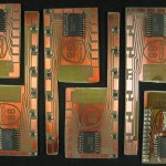 Update 2/10/12: I made up the other 4 latch boards at the W88 meeting last night, so we almost have the initial 6 boards. (I failed to put the per-LED resistors on the board used for the very first reflow test – I’ll have to do those by hand.) I cut the boards apart, solder-pasted them, laid out the parts, and reflowed all 4 at once on the hotplate at the meeting. Came out pretty well.
 When cutting the boards apart, the long (vertical in these pics) cuts are made with a hacksaw with the board in a vise (before the resistors are soldered on!). That inside cut was made by scoring with a cutoff wheel in a Dremel, breaking the boards apart by hand, then cleaning up the edges. I really need to be careful with the cutoff wheel, as there’s almost no clearance at the ends. I completely cut through one trace, almost completely cut another, and nicked a third. Not too hard to repair, but that was pretty sloppy.
Wiring, logic
Since the 74154s outputs are active low, the original design must have had the wire-wrapped common for each column connected to all the LED cathodes. We’ll use those wires, but hard wire them to ground.
We have to put positive on the other LED lead (anode) through the latch boards. Obviously we’ll need to rip out all the long wire wraps joining all those anodes. The latches are non-inverting, so the code will have to put out a high to light an LED.
The clock on the 75AC574 latches input data on a low-to-high transition. That means the code will have to:
– write the address of a column on the 6 address lines (74154 output goes low)
– set up data for that column
– write the next address on the address lines (our clock goes high and latches)
– set up data for next column …
Since the latches are not transparent, changes to the data while the clock is either low or high will not get written to the outputs, so I think this approach should work. But the test is the test. 🙂
Since an Arduino output pin probably can’t drive 64 latch inputs, we’ll need a few (4?) octal buffers with the Arduino driving those and each one driving some (16?) latches. Nothing is even started for that yet (but we don’t have 64 latches yet, so …)
Resistors
I’m not sure how to manage the series resistors. All the boards made up so far (4 of the initial 6) have all 220Ω resistors. If we want quite consistent brightness, we may have to tweak (some) individual resistor values. But to avoid the unpleasant task of unsoldering a board we just soldered in, we should do the resistor tweaks before soldering the board on. But we don’t know what tweaks (if any) are needed at that point. We may want a test jig to check the brightnesses of all of this column’s LEDs.
Since the voltage drop in the latch’s output circuit matters, maybe we should make up a latch board that starts up with all outputs high (some RC on the clock, maybe), with all 220Ω resistors, and with some kind of sockets (perhaps on a pigtail) we could plug briefly on to the column of LEDs we’re about to solder a latch to. Ideal would be to use the code and the existing wiring to light all LEDs in the previous column for comparison.
It gets stickier from there. If all the LEDs look good, fine. If one (or more) looks bad, how do we know what resistor value(s) to use? We’ll probably have only a small range of values to choose from – maybe 180, 200, 220, 270? Switchable resistors of all values for each LED would be a real hassle. Since I’m guessing low brightness will be the most common problem, I suppose we could have something like a header with the 2 sides of each resistor brought out. We could put a pot (just one end and slider) on a female pigtail, plug it across the existing 220Ω, and adjust for matched brightness. Given its value in parallel with 220, we could compute the ideal value and so make a good guess about which available value would be best.
When we get all the 74154s/columns working, we could step through each column with an Arduino driving all LEDS on (like the cylon code we have now, but manual increment/decrement) and look carefully at them, noting exactly which ones were questionable. That’s certainly the easiest first step, and maybe sufficient for spotting those (I hope!) few LEDs we’ll need to worry about.

Pingback: LED Hacking Night recap « Workshop 88