My UPS is a big old sine wave clunker retired from work many years ago. It works fine, but the only “management” info it provides is a dry contact closure when it’s on battery – not very useful to know how close to end of battery life we are during a power outage.
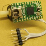
 There’s been a project on the list for years to monitor the battery voltage of the two large deep-cycle marine batteries that power it. Thanks to a donated Teensy, that project is starting to come to life. Sorry PIC, but I could write this in 10 lines of C instead of battling through PIC assembler yet again. I got the Teensyduino environment up with no problems. Here’s the prototype that let me get started.
The monitor’s job is simple: Measure battery voltage and spit it out serial once every few seconds. Actually measuring the voltage range of interest is more challenging. The battery runs ~28V fully charged, and the UPS probably cuts out when the battery drops to ~20V (not measured yet). If I just put a divider across the 28V to bring it down to the 5V range of the Teensy, the 8 volt range of interest is only about 30% of the A/D range, so I’d lose considerable precision.
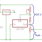
 By dropping a pretty accurate say 20V from the positive side of the battery, I get a nice 8V which I can then scale to the 5V range of the Teensy. I can use a negative voltage regulator upside down to do that. There are a couple of calibration issues, including setting the regulator to a low enough voltage that its dropout voltage is accounted for. Obviously the code needs 2 calibration constants: An absolute offset representing the regulator voltage, and a scaling factor to account for dividing the 8V (or whatever) to its 5V A/D range. That should be pretty easy.
(This approach came from expecting to use an 8-bit A/D in a PIC. With the 10 bits in the AVR chip, I could probably afford to keep it simple and just do a divider across the whole 28V. If I did that, the range of interest – 20-28V – would span ~30% of the 1023 count A/D range, giving me ~300 counts. I guess I should be able to live with that.)
The Teensy’a serial output will go through an opto-isolated path to another normal PIC node on the 485 network. The serial out bit should be able to drive the isolator’s LED without any trouble. Since that PIC’s UART is busy talking RS485, it will have to do bit-bang serial on some other pin. But the data rate is so low I could run that at 300 bits/sec or lower. It should be able to handle that rate with no problems. More to follow…
