Time lapse of tree cleanup

We had some impressive tree limbs ripped off in the storm 6/21.  Some were too big to even drag to the parkway.  I’m really hoping the city will come by and cope with them.

Since there wasn’t much going on with the driveway and since the script seems to be working happily (and since we have power again!) I moved the camera to look out over the branches in the front yard.  Let’s see what it captures.

I never expected to have the time-lapse script be useful again.  I hope it doesn’t turn me into a time-lapse junkie, if for no other reason than that it ties up my camera for days at a time!

Update 6/25/11: Some guy with a chain saw came to the door and asked if he could cut up the branches and keep some of the wood for firewood.  We said he was welcome to do so, and made sure the camera was watching.  Got a nice clip of him at work.  (Well, series of pictures.  Haven’t made it into a video clip yet.  But I will, I promise, and will post it here!)  He did a nice job, and by removing the largest branch made it possible for us to move the rest and clear the sidewalk.  Unfortuntately, the camera had stopped by the time we went out, so no clip of that.  Something about the shoemaker’s kids not having shoes…

Update 6/27/11: Rats.  Heard big noises outside and there was a crew with a chipper-shredder starting to get rid of the branches!  Bad news was that the camera was stopped – memory full.  By the time I could get a couple of directories moved off the card so there was a little room, they were gone.  So near, and yet so far!  For some reason, they stopped in mid-cleanup, so there’s more to do.  Maybe with an empty card I’ll come home after work tomorrow to a fully empty parkway and some actual pictures.  The one interesting thing I saw as I watched (since I couldn’t take any pictures!) was that there was a winch above the opening of the chipper-shredded.  They attached the winch rope to one very large branch (which it took 2 of us to haul onto the parkway) and hauled it across the parkway over to the c-s.  Since the winch was maybe 6′ off the ground, as the end of the branch with the rope neared the c-s, it was lifted about into position to be fed in.  That must be a real major labor-saving device for the crew.  Maybe more to come.

(On a side note, as I tried to cut the grass under where the removed branches had been (on both my grass and my neighbor’s) my very reliable 18 year old lawn mower started making nasty metallic noises and ground to a halt.  No metal in a quick check of the oil, but it wouldn’t run.  Possibly a bad ignition timing slip and a terrible knock, but it ran pretty much normally for the last few minutes – except for really nasty noise –  before it ground to a halt.  I’ll never know now.  I went out bought  a new mower, and the old one was gone from where I left it on the curb within an hour.  But with a little luck I’ll get another 10 or 15 years out of the new one – which may be as long as I’ll be cutting grass!)

Update 6/29/11: Success!  I looked out this morning and the last pile of branches is gone – and the camera is still working!  So no excuse for not making up a video clip – except that I have to go to work today.  But with a little luck I can post it tonight.  Watch this space!

Update 9/12/12: OK, it took a while.  The clip is here.

Posted in Time-lapse photography | 2 Comments

First cupric chloride board etch

I finally etched my first board in cupric chloride (with no extra oxidizer).  It was a little slow, but came out fine.  I heated the etchant some, but not as much as I typically heated ammonium persulfate, for fear of fumes.  It took 13 minutes with continuous manual agitation.

Board dipper

I formed a cradle with a handle out of #14 insulated wire to hold the board.  A little bending and it holds quite securely.  I dipped the board in the glass loaf pan dedicated to etching and immediately pulled it out and turned it nearly vertical so the spent etchant would drain away as much as possible.  I did a dip every 3-4 seconds and changed the orientation for draining every several dips.  Boring, but I’m sure it was much faster and more uniform than if I’d left it sitting in the etchant with no agitation.  The etchant left a heavy white deposit on the insulation of the wire after one use.  More on that later.

The etchant is a little thicker than the water-consistency AP I’m used to and also nearly opaque, so not so pleasant to use.  It started to turn from its pretty clear green state to muddier green-brown quite quickly.  (It’s “clear” only in thicknesses of maybe a mm.)  By the time the ~2.5″ square board (~typical 50% remaining copper) was done, the etchant was noticeably browner – between 0.5 and 1 g/l Cu+ concentration from Seychell‘s white card pictures.  His etch rate v Cu+ concentration graph shows times not a lot greater up to maybe 5 g/l, so some fears that my 0.7 l of etchant might give out too soon probably aren’t well founded unless I have a lot of boards to do at once.  And after 12 hours of aeration, it was clear, pretty green again.

Etchant tank

I found a rectangular plastic spaghetti storage container (at the Container Store) about 1.5″x3″x11″ that’s just about right for the smallish boards I usually make and the volume of etchant I have.  I’m hoping it will become the combination storage and aeration container for the etchant as well as being the etch tank.  The etchant would never leave that tank.  With a little luck, I can use the same aeration setup (a rectangular aquarium air stone) both for regeneration aeration and for agitation during etching.  It would be great if I didn’t have to stand around (breathing fumes) doing the dumb manual agitation dance any more!  But the steps before I can do that are making a right angle fitting for an air hose to the stone and a rectangular clone of the funnel top I’m using in the current glass jar to control splashing during aeration.  And probably making a base for it so it won’t tip over easily…

The one thing that might make me need to take the etchant out of the tank is some kind of crud deposits.  I suppose it’s copper hydroxide, but don’t quote me.  There was the white deposit on the wire I used to dip/agitate the board during etching, and a similar white deposit on the back of the board after etching.  Most surprising, however was a ring of deposit that had to be scrubbed out at the surface level of the etchant in the glass etch tank!  If these deposits are any indication, there may be a lot more cleaning than I would expect from this system.  I’ll continue to report on it.

Posted in Cupric Chloride Etchant | Leave a comment

Workshop 88 door lock

As part of upgrading the W88 infrastructure, we’d like better records of who’s in the space and when.  The new lock on the W88 front door only allows 2 combinations, and so isn’t very helpful in logging who’s there.

This project hopes to fix that by reverse engineering the connection between the keypad on the outside and the lock mechanism on the inside, intercepting keypresses from the outside, comparing them to a larger list of valid combinations, and if a valid one is entered logging that code and spoofing a valid code into the lock to open the door.  Bill and I have made some initial progress.

The keypad has 6 buttons and is backlit with 3 red/green LEDs.  While there are spots on the keypad PCB for other stuff, nothing else is populated on our board.

The connection between the pad and the lock is a 14 conductor cable terminated as two 7 conductor pads on the keypad and a 2×7 female header apparently on 0.05″ centers.

Before we took it apart far enough to see the keypad PCB, we figured that with that many wires, each button was probably brought out as 2 contacts.  Using an audible continuity tester in the good multimeter, we guessed what the connector layout might be and tried to find which contacts went to which button.  Nada.  We had some thin wire that fit nicely into the connector and even took 6 pieces of wire, picked 6 random holes and tried to increase our chances of finding at least something by connecting the continuity checker to them 3 at a time.  After a couple more tries that way, still nothing.  Concerned that it might use the conductive carbon contact technology in some cheap keypads and the resistance was too high to trigger the audible indicator, we even started looking at the ohmmeter indication rather than listening for the noise – still nothing.

After taking it apart enough to inspect the PCB, we visually traced the 2 connections to each switch and then had no trouble hearing the switch closures.  We were just unusually unlucky in the pin choices we blindly made initially.

The good news is that both sides of each switch are in fact brought out to the connector, so sensing which keys are pressed and spoofing presses to the lock shouldn’t be too hard.

Here’s the pinout of the connector, looking into the holes, with the key shown:


The pin numbers are numbered pads on the keypad PCB and match the numbers marked on the lock PCB male connector.  Keypad switch and LED pin numbers are shown.

No info at all on the single-row female header on the board that’s visible through the battery compartment except that it’s more like 0.08″ centers than 0.1″.

Update 6/10/11: OK, the 2×7 header from the keypad is “1.27mm”; the other as yet unexplored female is 2mm.  I’ve ordered M and F 1.27mm, and some M 2mm from Digikey.  <grumble>Shipping was as much as the purchase.  </grumble>  Started to make a little 6 push button array for dev/test.  Got a chunk of the key detect and main loop designed, at least in my head, during the 6 hours drive to St Louis for the square dance weekend.

Update 6/14/11: The connectors arrived, but I’m not going to have time to touch it until next week (since we’re going away to another square dance weekend and I’m working desperately on some recording electronics for it).  I did start writing some code over the past weekend before the design thoughts I had in the car evaporated.  (Sorry for the blurry picture.  My good camera is off taking pictures of the driveway.)

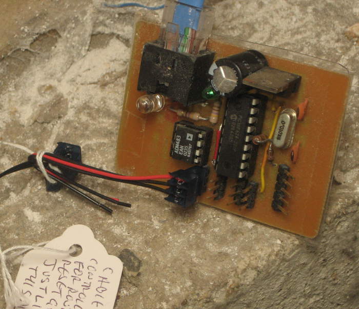
Update 6/20/11: Made a (first version of a?) shield to provide a place to terminate the cables to the lock and host the 2 reed relays I hope to use to spoof keypresses to the lock.  (This was the first board I’ve used cupric chloride etchant for.  Worked OK, a little slow.)  From the pinout above, I needed eight pins to the keypad (1-5, 6, 7, 8 ) and six to the lock (1, 4, 5, 6, 7, 8 ).  To keep the keypad LEDs working, 6, 7 and 8 must be connected straight thru, and to simplify the board layout while connecting those, the Pin 1 of each cable is at the far end of the termination pads; the two Pin 8s are adjacent in the center.  All the keypad switches are covered by pins 1-5.  If I use a minimalist code to the lock – like 1 1 1 1 – I need 2 relays to spoof the “1” and “unlock” keypresses, and of course diodes across the relay coils to protect the Arduino output drivers. I might have gotten away with MOSFETs or possibly normal transistors, but relays always work.

I avoided Arduino pins 9-13, as at least some Ethernet shields use those.  I put pads in for several other lines, most notably Tx+Rx, with an eye toward easy hacking if other functionality is needed.  While an Ethernet connection would be cool, it looks like all we’d really get is ascii strings, which could be handled just as well with a serial connection.  If I have to do that, I’d probably opt for RS485, using the same ADM483 TTL-RS485 chip the nodes in my home automation system use.  I’d use PoE or put power on the unused pins of the CAT5 carrying the RS485 signals to power the Doorduino.

During the meeting at the space Monday night I managed to solder up quickie cables to the 1.27mm headers that intercept the keypad connections .  (They’re ugly – those pins are really close together!)  But somebody brought a Makerbot and that was too interesting to ignore, so I didn’t even get to plug the cables into the lock.

A very incomplete bit of code exists, so maybe by the next time I can get in there will be something that might work.

Update 6/22/11: Most of the skeleton of the code is in place.  Still just stubs for reading from some computer to update the member code database and for reading the database from EEPROM, with 2 member codes hard coded in to test with.

I also tacked a little set of buttons on, hopefully wired just like the buttons on the keypad.  Approach for reading a key is to set one pin to output and write high to it, then read the other pin.  If it sees 1 the key is pressed, else not.  It sorta works, but I get way too many false positives – reading 1 when the key isn’t pressed.  I should have put pulldowns on all the lines – oops.  That’s the next hardware step.  Then I should be able to use the buttons to debug/test the keypress/member matching logic.

Update 6/24/11:  Pulldowns: Russ said floating Arduino inputs were _really_ noisy, and were especially affected by the state of the adjacent pins, so I did a quick test to see what pulldown value I’d need to get reliable reads of the keys.  Using the TestKey(key) function already in the code, I chose the 7/8 key, whose sense pin (5 from the table above, which maps to A1 on the board) had both physical neighbors (A0, A2) free.  I set A0 and A2 to be outputs, and did trial runs with those 2 pins in each of the 4 possible states.  To return true, the debounce logic in TestKey() must read the pin as high 3 times in succession, with 20 mS delay between.

In 1000 trial runs (4000 calls to TestKey()) with no pulldown, it got about 2600 false ‘true’ indications.  In every  case with both neighbors set high, it gave a false true.  For other cases it read some 0s correctly.  In 1000 trials with a 470K pulldown to ground, it read zero false trues.  A 1M pulldown seemed to do little or nothing.  All test runs were with the key not pressed; it always correctly reported true when the key was pressed.

Due to the unusual wiring of the keypad, where some pins must be set high to read one key while being the sense pin for other keys, the cost of the pulldown is that when I need to force a pin high, the pin’s output structure must source enough current to overcome the pulldown.  At 470K, that’s 10 μA – trivial for the Arduino pins.

I now feel free to use whatever value pulldowns – say 100K or less – I can find 5 similar 1/8W resistors for in my junk box.  The Doorduino shield will look a little uglier more interesting showing its history with the resistors tacked on, but function wins over form.

Later: OK, I put the pulldowns in.  Big and ugly, but they work, and the buttons seem to work pretty reliably.  Or at least the little test buttons work.  It’s never been connected to the actual keypad yet.

I did manage to screw up the wiring, though.  The pulldowns were supposed to go to ground – which is available right there about 0.3″ to the left of where the left sides of the resistors are connected.  I wrong-headedly fitted the resistors to go into the pad by A0 instead of ground pad.  Fortunately, I wasn’t using A0, so I set it as output and wrote a LOW to it.  Works, but it was dumb.

A little worse is that I think I didn’t need them at all!  The approach to test a switch was to set the pin connected to one side as output and write HIGH to it, then sense the other end with an input line.  Of course I needed the pulldown to make sure it was low if the switch wasn’t pressed.  But I think I could just invert the logic, write a LOW to the output pin, look for a 0 to say the key was pressed, and use the internal pullups on the input pins to ensure the input was in the high state when the switch wasn’t pressed.  (The analog pins do in fact have pullups just like the other pins.)  I haven’t decided whether it’s worth tearing the dumb resistors off or not.  But I hope next time I’ll think to do it that way.

Button detect logic seems to work, and I can reliably enter any of the three code sequences I’ve hard coded in and have it identify which sequence it is and call unlock().  Changed the #define for length of keycode from 4 to 5 and it worked exactly as expected (after I increased the database contents to 5 keys each).

Update 6/27/11: Went in to the space Sunday for cleanup day and had a little time before the others arrived, so I played with the lock.  The connectors do fit, but it will be interesting to find a way to get the cables into the lock.  The user interface from the keypad is not what I thought:  It unlocks as soon as the last key in the code sequence is pressed.  I thought you had to press the “Lock/Unlock” button as a sort of “enter” key, but that’s not right.  It’s a “Lock” button only, and will always lock the door.  I modified my code to a) not expect a Lock keypress at the end; b) to not send a Lock keypress as part of the spoofed sequence I send the lock to unlock it; and c) respond to a Lock keypress by spoofing a Lock keypress to the lock.  I couldn’t actually try it because I didn’t have a laptop to update the code and power the Arduino while plugged into the lock.

Russ got an Ethernet shield, and it seems to use the pins I left available for it.  It also has female connectors on the top so I should be able to plug my shield into it.

Likely access (without cutting holes in the metal frame of the lock) is down an empty space near the battery.  Unfortunately, there’s barely room for one cable, let alone 2.  Decisions to be made and work to be done!  Short term next steps are:

  • actually test lock/unlock commands to the lock
  • actually test keypad input to the Arduino
  • figure out how to modify the lock case to get cables into it and still connect the battery
  • modify the case, mount Arduino, etc

Mid term steps:

  • define protocol for database updates from computer
  • define protocol for lock activity log messages to computer
  • get (Russ to get) Ethernet connectivity working to implement above

Update 7/12/11: Got to the space and made some progress today.  Main goals:

  • verify that it could talk to the lock and to the keypad
  • try to see if that single-row header could be useful

I took the electronic/motor part of the lock off the inside of the door so I could work on it from the comfort of the table, and using the very crude cables I’d made out of Cat5 (almost completely inappropriate for the task) I plugged the Doorduino into the lock.  After some repairs to the clunky cable, I succeeded in sending both lock and unlock commands to the lock, both triggered by appropriate key press sequences on the surrogate keypad I’d hooked on.

While the lock command worked just as designed, the unlock command just produced lots of beeps from the lock.  I soon realized I hadn’t reprogrammed the lock to accept “1 – 1 – 1 – 1” as a valid unlock code.  Once I did that it unlocked fine.

Then I brought the Doorduino and the laptop over by the door and plugged it into the actual exterior keypad.  Sure enough, it recognized presses from the keypad, and when I entered the user code sequences I’d hard coded in, it identified which user it was and called the unlock function.  Great!

To facilitate testing the mystery header, I made a little breakout cable.  With power applied, I looked at the voltage on all the pins (with respect to the negative side of the battery).  Found some +6V, some +3.3, some ~0V.  Nothing surprising.  Since there were 14 pins – same as the connector to the keypad – with the battery out I tested for continuity from both end pins on the header to the 4 corner pins on the keypad connector.  Nothing.  It’s clearly not just alternate access to the keypad connector.

Finally, I connected a logic analyzer to the breakout (sorry for the cluttered picture) using battery minus as ground and caused the Doorduino to issue lock and unlock commands.  Since the analyzer only has 8 input pins, it took two runs to watch all 14 header pins.  While it showed a collection of hi and low levels on various pins, there were no transitions at all during lock and unlock events.  So much for the vague hopes that it might provide access to the lock motor pins.

I have figured out a little more about the lock from playing with it multiple times.  Looking down into the hole on top that the battery pack slides into, in this photo from Andrew you can see two white plastic guides that about line up with the mystery header.  I suspect strongly a programming or diagnostic card with a male header slides down into those slots.  Looking at the instruction card visible when you slide the cover off, in addition to a DIP switch and the “program” button, there are 2 small round white buttonish things near the top that don’t seem to do anything at all.  Having had them in my hand, they’re part of those white plastic guides.  (You can see most of the one on the left in the picture.)  I suspect strongly they provide access to a couple of tiny buttons on the programming/diagnostic card.  No clue what they might do, but at least that probably explains their existence.

I also learned that if it beeps a lot and the keypad flashes red and it will unlock but not lock, it needs batteries 🙂

Now that I know that I can operate the lock motor and read keypresses from outside and that the mystery header probably won’t be very helpful, the next step is to make much better cables from thinner, stranded wire, with strain reliefs and better insulation.  And there’s still the issue of moving the battery pack to make room for the cables.

Update 7/18/11: I didn’t have any suitable wire to make new cables, so I went to Fry’s to see what I could find for thin stranded wire.  Not sure, but 26-30 ga is probably what I’m looking for.

I stumbled on almost exactly what I needed in a floppy cable with the extra fine pitch ribbon cable.  “Normal” ribbon is 0.05″ pitch; the stuff with an extra shield conductor between the conductors that are used is 0.025″.  But most of the ribbons were one color, making it slightly more challenging to wire the cable correctly.  But I ran across an 18″ non-ribbon cable with lots of colors.  I’ll cut it up and it should be just what I need.

There’s been a little discussion about leaving the existing keypad functional in case the Doorduino (DD below) fails.  That requires different cabling, so I need a final group decision on which way to go before I can actually make the cables.  There are two basic options:

Option 1: The original design.

  • The original keypad goes only to the DD allowing it to read keycodes from that keypad for checking against the internal database.  The lock can no longer read the keypad directly.
  • The connection to the lock is essentially just enough for the 2 relays on the DD to spoof keypresses on the Lock and 1/2 buttons.  We program a code of 1-1-1-1 into the lock.  To unlock, DD makes a series of contact closures on the wires to the 1/2 button to spoof pressing that key 4 (or however many) times.
  • Pros: Can use existing keypad.  (Doesn’t rule out adding a different keypad later if we have enough I/O to connect it to the DD.)  The current wiring plan also allows existing red/green LED feedback on the original keypad.  Works now.
  • Cons: The existing keypad’s 5 buttons could allow for unintentional duplicate codes.  For example, 1-3-5-7-9 is just the same as 2-4-6-8-0.  Not a show stopper, but we need to watch for it.  If DD fails, only access is with a physical key.  (If we cache the database on the DD – as is planned – failure of the main computer does not affect access.)

Option 2: Leave existing keypad connected to lock.

  • Make cables so the relays are in parallel with the Lock and 1/2 keypad keys.  Probably not too hard.
  • User entry is from another keypad.
  • Pros: Original keypad works if DD fails.  Separate full keypad avoids duplicate codes.
  • Cons: Keycode 1-1-1-1 would work from the outside.  This is bad.  Need new outdoor keypad and to interface it to DD.  Not sure how LED feedback would work.

Update 7/22/11: Based on the feedback I received, I’m going to proceed with the original plan 🙂

I cut up the floppy cable and found the wire to be about perfect.  Soldering to the tiny pins of the connectors to mate with the lock/keypad cables was a challenge, but I think I did a pretty good job.  Here’s the color code.  It’s the same for both cables.

1 blue
2 red
3 yellow
4 green
5 purple
6 gray
7 tan
8 pink

I put paper between the rows of pins and encased the pins and a little of the wire in hot-melt glue as a strain relief and insulator.  While I believe firmly in the better reliability of pigtails – avoiding an extra connector pair – I also replaced the original soldered-on pigtail approach with a 0.1″ header.  I figured if I needed to remove the DD (like to program new user codes until the network stuff was in place) I didn’t want to have to take the lock apart to get to the connectors.  After I’d put the female header on I realized I could just unplug the shield from the Arduino (now a Diavolino).  Oops, too late.

I used a hot-melt strain relief on the 0.1″ male end of the cable as well.  It turned out that a soft clear plastic fan shaped cover from the floppy cable fit almost perfectly over the header, so I used that, too.

It’s pretty much ready to go for testing.  I hope I kept the wires straight, but the test is the test.  And with the much thinner wires, there’s a vague hope that I can squeeze them in without extending the battery holder!  We’ll see.

I’m seriously considering removing the dumb pull-downs, since they’re both ugly and unnecessary.

Update 7/23/11: Well, I thought it was ready for testing.  On looking a little closer, I realized I made a mistake and also made a decision (bad, in hindsight) that could have, but didn’t save my butt.  I need 8 (of the 14) pins to go to the keypad to get all the switches and the LEDs, but only 6 to go to the lock (since the DD only has relays to spoof 2 of the switches).  Murphy won, and I put the 6 on the female instead of the male.

A little worse, I thought about running all 8 wires to both connectors, since the pinouts were identical (obviously, since they interpose between 2 connectors that plug into each other).  I already had all 16 terminated at the DD end.  That way if something weird and unexpected happened – like DD was redone to spoof all the switches – all the wires would be there and connected.  But the chances of needing to spoof all the switches (adding 4 more relays to the DD shield) were pretty slim, so I took the short cut of not soldering in the other 2 wires, saving maybe 2 minutes.  (I did just fold them back into a bit of heat shrink, rather than cutting them off.  I guess I learned something from past flubs.)

Of course the unexpected thing didn’t have to do with the relays – just with being dumb and picking the wrong connector to shortchange.  Switching the 2 connectors’ functions – keypad/lock – at the DD end is trivial:  the 16 pin header is symmetrical, so flipping it over would swap the 2 cables.  If I’d only connected all 8 wires on both connectors, I’d be all set.  But I didn’t.

You can see the bit of card stock I put between the rows as insulation, and the fingerprints where I formed the hot-melt while it was still hot.  (Wetting your fingers works great!)  You can see the 2 unconnected pins – 2 and 3, referring to the diagram earlier.  I also cut off the unused 6 pins, since I don’t even know what they do.  Looking at it closely, it looks like a pretty effective insulator and strain relief.  Fortunately, pretty wasn’t in the requirements 🙂

OK – now how to fix it?  I do have a spare connector (ordering 2 was cheap insurance), so I could just cut the wires off and start again.  And I think I have enough wire that it would still fit.  Of course all the connections are now potted in hot-melt, and I tried extra hard to work the stuff in to really surround the pins.  So reusing the existing connector would require removing the hot-melt – non-destructively.  I guess I’ll try using the hot air station and see what happens.  But I sure am glad to have that spare connector as Plan B!

Much later…

Interesting process.  I chose to try to surgically remove the glue just from around the pins that needed their wires.   I used rubber bands and a pair of pliers to hold the connector, and a desk vise to hold the pliers.  That let me get a pretty good angle for the hot air gun and the toothpick I used to scrape out the remelted glue.  Here’s a little clip: RemovingHotMelt.

The hot air station remelted the glue just fine.  I could pick out the glue from around the pin of interest pretty well.  I finished cleaning up each pin by scraping it (cold) with an Xacto knife.  I tinned each pin after I removed the glue, and it tinned fine.  A little careful soldering, and I had the connection I needed.  After soldering both wires in, I added some more hot-melt to remake the insulator/strain relief.

After

An interesting effect of using the hot air on the glue is that as it melts from the outside in, it effectively removes the ugly cloudiness from fingerprints introduced as I shaped the still-hot glue with wet finger tips.  It’s still bad, but with the glue more clear, it’s a little less ugly.  I’ll have to remember that trick the next time I make a hot-melt strain relief!

Each wire tested OK with a continuity tester, so I think I’m back to where I thought I was yesterday:  It’s ready to test out on the lock.

Update 7/26/11:  Major progress this evening after the LED scrolling display hacking session.  First, the new, thin wires fit past the unmodified original battery pack.  That simplifies things a lot.  Then I tried each connector (to keypad and to lock), and each worked by itself, so I tried the whole thing end-to-end.  First I had to stuff the connectors behind the lock and get it to fit back on the door.  After a couple of false starts, I got it all to fit.  Test time:  And it works!  I could use the keypad outside to punch in the user codes I’d hard coded in and the door unlocked and locked and logged user access just as it should.

Now for a touchier consideration:  It was a (small) hassle to get the new connectors stuffed inside the lock, but if I unplugged the DD, the lock wouldn’t work.  And the Doorduino had no mounting or source of power, so I couldn’t leave it in place.  Fortunately, I now had all 8 pins brought out from  both the keypad and lock connectors.  I dug around in my parts box and found a long enough female header to cut a 16 position header that would mate with the connector to goes to the DD.  Eight bits of wire and some soldering later, I had a jumper cap that looped back the connectors, pin for pin, and the lock worked again.  I taped the connector (with loopback cap) to the door and called it done for the night.  If you can’t leave wires duct-taped to the front door in a hackerspace, where can you?

Next software steps are putting the user database in EEPROM, isolating the initial user code definitions to a nicely structured separate header file until there’s network connectivity, and starting the network stuff.  Next hardware steps are arranging for power over the network cable (it won’t be proper PoE, since that requires extra hardware on the network shield) some kind of mounting, and probably at least a minimal enclosure.  I’d be delighted if someone else built a beautiful enclosure for it, but I’d like something to keep it from catching on people’s clothes, etc.  I may take off those ugly pulldown resistor too.

Many thanks to Andrew and new visitor Dan Gray for sticking around to help!

Getting close!

Update 7/30/11:  Tested out DD duct-taped to the door with a battery pack on Makerbot build day Friday 29th.  We went to lunch and it locked the door when we left and unlocked it for us when we came back!

As an interim arrangement, it currently gets user codes and names from a clean, separate header file as PROGMEM, puts them into EEPROM, then uses the data from EEPROM for keycode validation as it will in the final version.  It doesn’t deal gracefully with the number of entries yet – that will probably end up as the first byte in EEPROM.  The header file entries are pretty easy to manage, and look about like this:

userCode userCodes[] = {
    "Bob",{0,1,2,3,4},
    "Ted",{0,2,1,3,2},
    "Carol",{4,3,2,1,0},
    "Alice",{0,1,2,1,0}};

I’m off to a square dance week and since the Arduino dev environment isn’t physically very big, I’m bringing the DD with me to finalize the software a little more.  I hope to fix up the EEPROM stuff and get it to at least acknowledge the Ethernet shield.  I’m confident enough that I can get it to work without the dumb, ugly pulldown resistors that I pulled them off the board.  Did my heart good, but that logic now also needs to be fixed before DD will work again.  I may be able to make at least some design headway on figuring out how to get power over the Ethernet cable (but not PoE).

Update 8/8/11:  Got keyboard sense working with pullups (no more pulldowns!), cleaned up EEPROM stuff some so the database (user codes and names) is in a header file that is conditionally compiled.  If present, the data from the header file is written to EEPROM; else there better already be something in EEPROM!  In any case, user code validation and name lookup for logging is always from EEPROM.

I tried to get the Ethernet shield working with some example code.  Some LEDs on the shield blinked, and it indicated link, but didn’t work at all.  Wouldn’t even respond to ARP requests.  Is the shield bad?

I was using it with a Diavolino, so I tried it with a real Duemilanove.  It worked fine!  The shield uses SPI via D11-D13.  For reasons known only to the developers, it picks up those signals (MISO, MOSI, SCK) not from actual pins D11-13, but from a non-standard socket that plugs into the ICSP header.  The ICSP pins and D11-13 are connected on an Arduino.

For reasons known only to a different set of developers, the Diavolino has chosen to move the ICSP header over about 1 cm from where it is on a “real” Arduino, so the socket  under the Ethernet shield doesn’t have a prayer of connecting to it.

How to work around this?  I could take the expensive way out and use a real Arduino.  I might be able to drill holes in the Diavolino, glue pins in, and run little jumpers to connect them.  Ugh.  Or I could hack the  dumb Ethernet shield to get those signals from the normal pins instead of the ICSP header.

Since (IMHO) it’s the dumb shield’s fault, I just hacked that board.  Three wires, and now it works with any Arduino or Diavolino.

Now it just needs power.  The RJ45 jack on the shield has 10 pins – not the 8 one would expect.  (That’s not counting a couple extra for the link and activity LEDs and the shield.)  And a continuity tester shows both wires in a pair (say ora/whi) are shorted together when a cable is plugged in, and the two come out on only one of the 10 pins!

(Time passes; Google informs.)

OK, it looks like this is a Mag Jack – one with the “magnetics” (transformers) built into the jack.  There are 6 heavy pads next to the jack, one connected to each of the 4 pairs in a CAT 5 cable (two apparently unused).  (You can see them in the pic above, with heavy traces running to 2 of them.  Two similar heavy traces are on the other side of the board.)  They’re presumably the center taps of transformers on each pair.  I don’t want to mess with real PoE, but I’m guessing (yes, it’s really a guess at the moment) that I can put say 12VDC on the unused pairs (both wires in one pair +, both in the other -) and get it out on those heavy pads – and without touching the pairs that carry the data. I was surprised that after lots of looking at schematics and details of the Ethernet shield (of which there are many versions) I couldn’t find that info and had to reverse engineer it.

There’s what looks like a nice heat-sinked regulator on the board.  I wondered if it was used by PoE and if I could hijack it.  But I think it’s just a 5V-3.3V regulator to run the W1500 chip.  For the record, I think the PoE support on the board is implemented by a third-party add-on bit of hardware.  So I think we need:

  • a power injector – a 12VDC wall wart and 2 specially wired RJ45 females
  • a 5 V regulator (and caps) to live on/attached to the shield, sourcing from the heavy pads, providing power to the 5V pin on the standard Arduino header
  • testing!
  • mounting for the DD, including some protective casing
  • cabling across the door, around the frame, and off toward network and power

That would leave us with a functioning DD, less logging.  User codes are still compiled in.  But the network stuff wouldn’t be in the critical path for operation.  If we wanted some logging, we could write to the micro SD on the Ethernet shield, but no effort has been made toward that as yet.  (But I hear there is a lib to support FAT on the SD.)

Posted in Workshop 88 Stuff | Leave a comment

LED replacement bulb

My friend Ed had a burned out bulb in the climate control panel of his Chrysler van.  The rather unusual bulb is not available by itself – only by buying the complete $400 control panel.  Thanks, Chrysler.

After slipping off a clear blue rubber shield and taking the assembly apart, the bulb looked sort of like a miniature Christmas tree bulb.  But those are typically 1.5-3V, and wouldn’t survive very long in a 12V application like this.  I did find that a 14V 8640 bulb looked like it would sort of do, though it’s a little shorter.  And I even found one for $1 (plus $5 shipping!!) on Ebay.  That will be plan B.

Since I had some small blue LEDs, I decided to try to make an LED replacement.  I cut the LEDs down in various dimensions so one could straddle the other while staying within the original bulb outline.  With 2 LEDs at ~3.5V in series, a little calculation and experiment showed a 470 ohm resistor would be about right.  At 20mA it would dissipate ~0.18W – more than the cute little 0.1W job in the foreground.  I didn’t know whether I could fit a larger one in, though.

By drilling the base a little I did manage to fit the larger resistor in, and put the whole thing back together.  The contacts  were the original wire leads from the bulb, wrapped around a nicely formed base.  I wrapped the resistor and LED leads back in the same pattern, but they were considerably larger diameter than the original leads, and I didn’t know how tight the tolerances were.  So I relieved the base a little with a Dremel so the fat new leads would sit lower, but with their top edges about where the top edges of the original wires had been.  Approximately.  Maybe.  And of course unlike the original bulb, this one is polarity sensitive, so I marked the + side.

Since “the test is the test”, I’ll have to report back after his auto shop folks put it in for him how it worked out.  But it does light a pretty blue on 14V.  It’s really hard to take realistic pictures of lit LEDs.  Switching back and forth looking at the camera screen and the real thing, the very exponential response of our eyes compared to the camera sensor was very obvious.  I almost tried a double exposure with one very underexposed to capture the LED realistically plus a fill flash to get the foreground, but didn’t.  Maybe next time.

Update 7/10/11: The LED replacement bulb got installed.  Here’s the console (sorry for the flash) and how it looks in the dark.  The new LED bulb lights the lower right portion.  It’s effective and pretty, but much bluer than the original equipment bulbs.  I suppose that qualifies as a successful effort.

Posted in Miscellaneous | Leave a comment

Time-lapse of driveway repair

I’ve been tempted to do a little time-lapse photography for years.  My office window looked out over a view that I think would have made a great quick video covering maybe a whole year.  With a pic at a given time most every sunny (or cloudy) day (or both – make two clips?), from a marked spot at the edge of the window, the seasonal changes would have been quite interesting.  But I don’t work there any more, so the opportunity is lost.  Duh – I guess I could do the same from the house.  I’ll think about that.

But in the short term, the city is about to tear up and replace the curb (“approach”) and part of the lower part of my driveway (“apron”) .  I thought that might make a nice TL clip with lots of people and machines moving around.  My Canon SD600 is one of the cameras that the Canon Hack Development Kit gives you lots more control over than the stock firmware does.  One of the many capabilities it offers is scripting – including a simple mechanism for taking TL sequences.  While an older version I had on my SD card didn’t work quite right, after downloading and installing the latest one I had a reliable timed-shot tool.

Power was the first concern.  The crummy batteries I have (see posts on Li-ion camera battery) wouldn’t begin to last the hours I needed to cover, and the camera doesn’t have an external power input.  But DC is DC, so if I could spoof the form factor of the battery and its contacts I should be able to run from an external supply.  And the camera does provide a hole in a convenient place for the wire to come out!  (There must be a commercial adapter available – I didn’t look.)

Fake and real batteries

The hack was a piece of ~1/4″ plywood sized just like the battery.  I notched some corners to deal with internal stops that prevent you from putting the battery in backwards.  (OK, I notched BOTH sides – the wrong side first.  Boo.)  I cut notches at the spacing of the original contacts to “inlay” some little bits of 0.008″ brass strip.   Since clearance for the battery was tight, I Dremel’d out gooves for some speaker wire before soldering it to the strips and epoxying them all in place.  I drilled/ground out a place in the end of the wood to match the convenient hole the camera provided for the wire.  After a little fitting and making really sure I had polarity marked correctly, I tried it out with my workhorse HP bench supply.

Fake in place

No luck.  Camera wouldn’t even turn on.  That supply is current-limited at 400 mA – and that wasn’t enough to run the motor to extend the lens.  To my amazement, I couldn’t come up with another supply with both enough current and low enough voltage to keep a voltage regulator from getting hotter than I wanted.  So I resorted to a true hack – with all the negative connotations – of putting the real battery in parallel with the bench supply to handle the current peaks.

NOTE:  Don’t ever do this.  Putting a battery directly across the terminals of a power supply is a REALLY BAD IDEA.  You’re essentially making a battery charger with NO current limiting.  This is a really dangerous hack!

The unholy hack

Discharger battery contacts

From previous battery discharge testing, I’d built a little jig with adjustable brass spring contacts that would fit this particular battery, so it was just some clip leads to hook it all together.  I figured if I was very careful, the stupidity of putting the battery across the supply wouldn’t bite me.  So I carefully preset the supply voltage to the open circuit battery voltage, watched current drains, repeatedly felt everything to make sure nothing got hot, rechecked voltages frequently.  I got away with it, and it all worked exactly like I hoped it would!  Now I had the basic hardware in place.

Camera in place

How often should I shoot?  The 2GB SD card is a little over 700 shots at full resolution.  If the work day is say 6 hours, that would give me ~116 shots/hour.  Let’s call it 30 seconds, and if they’re still working and I’m out of room I’ll swap in another card.  I set up the script for 30 sec.  Done.

I put the camera in the window and fired it up on the day they were supposed to do the work.  Unfortunately, due to recent rains, the schedule had slipped.  I got a nice clip of shadows moving across the driveway, but no workers.  But everything’s in place, and I think I know when they’re expected next.  I’ll post the clip when it’s done.

Update 5/31/11: Got some action today.  The Animation Shop software had trouble importing all the pictures, so I only got to see a little of it.  I hope the lower res pic today help. I ran out of memory at an inopportune time on this first work day, and I’ll have to leave the camera on its own tomorrow.  Taking full-res pictures is overkill for what will end as a video clip.  I set up for lower res that will give me ~1800 pictures this time, and cranked the delay down to 20 sec.

Update 6/3/11: The original high resolution pictures were completely inappropriate.  I got 10 hours of 640×480 – 1800 pics – in 360MB yesterday and it looks fine and only took 1/5 of the memory card.  I cranked it down to 10 sec interval (from 20) for today and expect fine results.  I’ll bet 5 would be better – might change later today.  I’m learning my way around some tools to find the ‘good’ parts and make a clip from them.  For something like this only the ‘good’ parts are worth keeping.  I’m looking forward to a pretty good clip out of all of it when it’s done.

I’ve been using the battery indicator on the camera to tweak the power supply.  While it dips after a shot, I’ve been keeping it at what it shows as 50-80% capacity.  Voltage at the supply is about 4.1V, and the battery is not warm at all.  The camera does run warm, but not hot.  Looks like it’s working well and I think it’s just about where it ought to be.  I do turn the supply off at the end of the day after I turn the camera off.

Update 6/4/11: Bummer.  I heard some noise this morning (Saturday) and saw a guy cleaning up some of the cement forms.  I ran into the room with the camera (which I had cleverly gotten all set up the night before) and fired it up.  (This involves turning the camera on in playback (not camera) mode, going into the menus to do a “firmware upgrade”, going to camera mode, watching the script auto start (a good thing), realizing it was not zoomed right (a bad thing), hitting the ‘print’ button to take it out of CHDK mode, changing the zoom, back to CHDK mode, maybe restarting the script.)  Unfortunately in my morning foggy-headedness, I forgot to turn the power supply on.  The battery in parallel with the supply allowed it to start, fooling me into thinking all was OK, but died after a  dozen pictures.  Oh well – that should keep me from making that mistake again!

Update 6/14/11: Sorry no video clips yet 🙂  But I have reviewed the some 40,000 pictures the CHDK script on my camera has taken, and identified the tiny fraction during which some construction activity is taking place.  Nothing has happened in the past couple of days (although I can get into my garage again).  There is still blacktop repair to both the street and the driveway, so I still fire up the camera each (week) day, hoping to catch the last bits of work.

The camera seems to have a limit of maybe 2000 pictures per folder, and so makes a couple of new folders (with names like 115CANON) each day.  The integer part of the image file name wraps at 9999, and the camera also makes a new folder when the number wraps back to 0001.  I grind through each folder with the free File Renamer Basic to add a digit to the number range so I end up with unique montonically increasing numbers.

Thankfully, the Windows Photo Viewer cycles through pictures pretty fast (~26pic/sec on my PC) if you hold the arrow key down.  That let me view a boring “video” of moving shadows interrupted by occasional fits of activity by bobcats and cement trucks.  There is a real hotshot bobcat driver, and standing outside I took a couple of little video clips of him with the camera on my Android phone.  I’d really like to include those in the final video, but unfortunately, that camera records to some strange .3gp file format which I haven’t found a transcoder for yet.  Yet.

Update 6/21/11: They still haven’t done the blacktop repairs.  But the good news is that I think I’ve gotten the script working just about as I’d like.  I thought the same thing when I left it running Thursday morning when we went away for the weekend.  I’d finally found a way to make it shut down, and found a “seconds since midnight” function so I knew what time it was.  I set it up to run from ~7AM-6PM each day, and to shut down after a total of so many pictures.  I didn’t have completely accurate info on the number of shots the card would hold, but worst case (wrong) it would just run out of memory in the afternoon on Saturday – which wasn’t a big deal.

Unfortunately, running out of memory is kind of a big deal for the script, since it throws an error and stops the script!  I came home Sunday to a camera with a full card (as expected) but still on and hot.  Rats.  But now I’ve also found a “free memory” function, so it now runs only during the hours I choose, and if either some max total number of pictures is taken or free memory is below some threshold it will shut itself off.  And I also figured out how to turn the display off and still run the script.  (If you click the Display button while in “Alt” mode – like in a futile attempt to turn the display off – it turns on “raw” mode, which records an additional raw image – at ~8MB each – with each picture, and chews through the memory card in no time.  Go out of Alt mode, press the Display button ’til the screen is off, then (blindly) press the Alt (print) button once (only!) and start the script.  I put a beep in to reassure myself the script had actually started if it was outside picture taking hours.)

So now it will take care of itself for a couple of days unattended, and shut down appropriately.  I think the only copy of the script is on the card, but I’ll post it here some time when the camera’s not busy.  Now if they’d only fix the driveway…

Update 6/22/11: Looks like the script did all the things it was supposed to do!  Here’s the script:  jimtest.bas

Posted in Li-ion camera battery, Time-lapse photography | 1 Comment

House monitor on Linux!

I’ve been trying to migrate the main server program for the home automation system off the main PC for a couple of years.  It’s a hassle to shut everything down gracefully when Microsoft pushes down yet another must-reboot update, and of course I can’t let it reboot automatically.

The target for the migration has been Linux on a cute little Pogoplug.  I’ve collected a couple of them over time (so I’d have a spare) and gotten the open source plugbox distribution on all of them.  I might even donate one to Workshop 88 for a combo monitoring system (maybe just motion sensors and door-open switch for starters) and a box I can log into and do things like pinging my own system from ‘out on the internet’ (using some kind of dynamic DNS to deal with the fact that we don’t have a static IP at the space).

While the main program is in perl and so should be pretty portable, there were a lot of roadblocks.  I’d been using a Win32 serial port module to wiggle RTS to control TX/RX for the half-duplex RS 485 serial connection to the monitoring nodes.  I’d also been using the Term::ReadKey module that is hooked into some Win32-specific raw keyboard routines so I could have some control over the main program from the window it was running in.  The serial hardware was a home-brew RS232-485 converter, and of course there’s no RS232 on the Pogo.  I’ve been hacking away, testing solutions to problems one at a time in isolation, but the pieces weren’t integrated until just now.

I found a nice cheap USB serial board (on Ebay, from China, of course) with the good old FTDI chip on it for which I knew the linux distro had a driver.  That has RS232, TTL, and RS485 outputs, and auto-sense TX/RX switching for the RS485, taking away the problem of messing with RTS for direction control.  While the wiring around the house for the network of sensor nodes uses CAT-5 cable and RJ45 connectors, the data is just one pair (brown/white).  (I use the other 3 pairs to carry unregulated 12V to power the nodes.)

Fortunately, the keyboard input is very localized, so replacing it with something else shouldn’t be too hard.  I settled on the brute-force approach of a signal handler in the main program that reads a file of user input, along with a small separate script that gets a command from the user, writes it to the file, and sends a SIGUSR1 to the main program.  There’s even a reverse channel to get output from the main program back to the user interface script.  (Prototypes of that are tested and working, but not integrated into the real program yet.)  I wanted a separate program so I wouldn’t be locked down to stdin/stdout on one window.  Aside from problems of running the program from a ssh session that might go away, I wanted to be able to do something like sshing in to the Pogoplug from the netbook while I was outside tuning up the landscape watering which is controlled by the automation system.

In the short term, I just ripped the keyboard input section out, so I have no control, and the only output is stdout in the window I start the main perl program from.  That will do for a little while until I hook the signal-based user interface in.  And the serial channel timing still needs some tuning.

But it’s up and running and sending data to the web site – woo hoo!

Update 5/24/11: First:  Huge thanks to commenter Stephen for dramatically improving the stability of my Pogo!  It had been failing to boot to Plugbox after a power cycle.  The fact that I could get it booted correctly after a couple of tries, or from a reboot issued on the serial console is not very helpful if I’m away on vacation and there’s been a long enough power outage to drain the (very large) UPS batteries and it has to come up on its own.  I had another Pogo that didn’t exhibit the symptom, and it eventually dawned on me that I’d hacked the bad one a year or so before the one that worked.  I reloaded the latest U-boot bootloader, and voila! – it comes up every time now.   If it hadn’t been for the conversations with Stephen, who knows how long it would have taken to figure that out.  Thanks!

Well, it was up and running for a day or so.  Unfortunately, the cron thread that knows when to turn the sprinkler system on couldn’t talk via the global variables needed to get the main program to actually operate the valves.  I just reseeded part of the lawn, and really couldn’t afford to have the sprinklers not work while we went away for the weekend, so I had to go back to running it on the main PC  😡

[Mildly interesting aside: There’s an occasional failure of the ftp append function that adds new data to the big file on the web host every 5 minutes, and that failure occurred some time shortly after we left for the weekend 🙁  The failure results in losing all the old data, including a startup line with a time offset needed for anything to work, making the house monitor page useless until I fix it by copying a bunch of older data (with the necessary startup line) from the PC to the web host.  I did that (after we got home), but there was an ugly anomaly in the data – basically no data for a day or so.  D’oh – that was when the Pogo was collecting data, not the main PC!  So I ftp’d the datafile from the Pogo to the main PC (it’s the same perl program, so the data format is identical), did a little hand editing to put that block of data in the right place, and pushed the big file back up to the web host.  Anomaly gone.]

I’m using the threads::shared perl module, and it allowed globals to work fine between threads on the PC – but not on Linux.  After a couple of rounds of hacking, I found the “nofork=>1” option in the Schedule::Cron module I was using to be able to use a crontab-like file to control the sprinklers.  Windows doesn’t really have a ‘fork’ capability, though Linux obviously does.  When the cron module actually forks, there’s no way for globals to communicate between processes.  Telling it to not fork – even though the host O/S supported it – fixed the problem.  So while there’s still no user interface, with a little luck the main program will live on the Pogo for the foreseeable future.  I will implement some user control (via signals) soon – but it’s less urgent than keeping my new grass from drying out.

Update 6/4/11:  Major progress! Inspired by the fact that the bedding plants are planted and I really don’t want to have to worry about watering them, it’s time to get all the landscape watering plumbing hooked up, working, and not leaking too much.

But the last part involves testing the automated system.  Back when it was run with X10, I could use an RF X10 remote controller to turn the valves on one by one.  But after a couple of flooded gardens due to latching relays and pathologically worst case timing of power outages, it’s all controlled by my own hardware now.  There are in fact physical buttons on the sprinkler controller in the basement, but that’s an awful lot of hassle for the several valves and zones I have to test.  I should just be able to do it from outside.    Unfortunately, the control program on the Pogo didn’t have a user interface (yet).

It does now!  I got the SIGUSR1 sender working and hacked almost all the old functionality into the program in response to the signals.  In particular, I can now ssh into the Pogo (say, from a netbook over wifi) and control the sprinklers!  And stdout is now redirected into a nice file I can do a tail -f on if I want to see it.  (Rolls over at midnight, keeps one old file.)  And both the main program and the ping stats script now start in an rc script at boot time.  It’s really close to in final form.  Woo hoo!

Update 6/9/11:  Oops We just had the first power outage since hosting the house monitor on the Pogo.  It failed because – it wasn’t plugged into the UPS!  During the months of on-and-off (mostly off) development leading to actually running the app on it, it was just sitting out (on top of the printer, actually) so I could get to it easily.  When it actually ran, I was so happy I forgot about production details like putting it on the UPS.

I was sitting next to the Pogo (on the main PC) when the power went out.  The PC of course was on the UPS, so was perfectly happy (and was the only source of light in the room).  But the Pogo was dark.  Scrambling around with a flashlight, I got it plugged into a more appropriate outlet.  But no network.  As part of just throwing it together, the closest network connection was an extra port on a secondary wireless access point.  But since that’s not the main router, it’s not on UPS either.  More rooting around with a flashlight under the table, and I got that up and the Pogo was on the air again.

Of course one of the corners cut in the minimalist Pogo(/Sheevaplug) design is that there’s no hardware clock.  And while I do have ntpd running, when the Pogo booted there was no network, so it couldn’t figure out what time it was.  There’s now one “STARTED” line in the log with a timestamp of Wed Dec 31 18:01:16 1969.

It was raining (and thundering and lightninging) when the power went out.  I had just yesterday set the cron file up to run all the sprinkler zones.  But given the significant rain, I wanted to turn them off for a while.  The “disable all watering for N hours” feature of the user interface is one of the very few I didn’t implement.  Rats.  I hacked the cron file (from a laptop on battery – the main PC was off to conserve UPS battery) and restated the cron stuff (a feature I had in fact implemented), so at least the sprinklers didn’t go on this morning.  Now if I can just remember to unhack the cron file and restart it…

Update 6/30/11: It’s getting more stable.  (Actually, I figured it was already pretty stable – wrong.)  I tried to clean up the code a little by putting repeated code in little subroutines.  And then I misspelled the name of a sub in one place, so it crashed days later when that code leg was executed.  It records stdout to a file.  I tried several times to make that file roll over (keeping one previous version) at midnight.  That mostly just didn’t work due to various errors, and crashed at 12:01 once or twice.  It reports a bogus router reset at every restart due to a self-describing data header in the data file that is misinterpreted.  I think I fixed that one today.  And I finally got pkill to work to clean it up and made a start/restart script that runs it nohup so I’ll have a clue what went wrong next time it crashes.

But it’s a real blessing to be able to ssh in to the box and fix stuff remotely, and another to be able to reboot my PC without going through a graceful shutdown dance, so I’m still very pleased with the current setup.  And while it didn’t last nearly as long as I expected on the big UPS during the last big power outage, if I can get the big PC to shut itself down automatically there should be lots of battery for the Pogo (and network stuff).  And it worked fine sshing in over wifi when I had to test out some sprinkler system repairs!

Update 7/3/11: Bitten by the “you can’t have it all” thing again.  The main perl program redirects stdout to a log file.  While it’s sometimes very valuable for troubleshooting, that info isn’t very relevant after a day or so, so I decided to have the file roll over around midnight, keeping one old version (one day’s worth) of the file.  (And avoiding a dumb out of disk error down the road.)  After *way* more failures that I expected for a simple task, I recently got it working, and thought I was done.  Not quite.

The transport code that ftps updates to the web host also reports its successes and failures to stdout.  But after a midnight rollover, that information went into the old file – not the new one!  Well duh – it forks a separate process for the transport code, so closing and reopening stdout in the main process can’t possibly change where stdout in the child process goes.  OK – how about rewriting it so the transport code is a separate thread rather than a separate process – and so can properly share the filehandles?  But that won’t work:  the reason the transport code was in a separate process (besides the fact that I didn’t know how to use threads when I wrote it) is that it may block for long periods on ftp/network problems – and I don’t want to block the main program for that long.  So unless I could find or write a non-blocking ftp package, having a separate process is appropriate.

Yeah I suppose I could have the transport code write its output to a little file, have the main program look for that file and on finding it write it to stdout/log and delete the file.  Ugh.  Or I could put similar rollover code in the transport code.  (But I can’t just copy all the code, since it removes the old log file.)  And even so, there’s a race condition at rollover time.  And closing and reopening stdout to point to the right file each time it tries to ftp something is asking for trouble as well.  It doesn’t write a lot – I suppose it could have its own log file.  Ugh.  Before I made the log roll over it was all in one place.

Why can’t I just have it all?

Update 10/1/11:  After a sad story about trashing the Pogo while trying to use it remotely to hack into my main PC, I’ve rebuilt the little server to the best it’s ever been, complete with a working backup mechanism.  It has the latest image from archlinuxarm.com (not plugapps.com any more), Device::SerialPort rebuilt from source, ntp stuff that works great, Samba so it can talk to the PC, all hosted on a 4GB (instead of 1GB) thumb drive.

It’s far enough along that it’s not really a development platform any more, so I’ve moved it from the computer bench to a fairly final home in the basement, near the switch and other network stuff.  Cables are remade to just fit, and dressed in a not too ugly manner.  The plate mounting the RJ-45 jack where 12VDC is injected into the network had a spare hole, so I added a second jack to connect to the Pogo now that it’s nearby.

It’s an appliance (if a different one than the manufacturer imagined), so it’s appropriate that it should live pretty much out of sight.  I have on occasion used it to serve files to people, but there’s one open USB port quite accessible on the front for sticking another thumb drive into.  Sure, there will be further software tweaks, but at this point it’s pretty officially “in production”.  Yay!

Posted in Home Automation | 11 Comments

Electronics workbench revamp

Background

My electronics workbench is in awful shape.  It hasn’t been cleaned up in several years, and has such a terrible pileup of debris and leftovers from previous or in-progress projects that I can’t free up more than 10 or 20 in² of fairly free working space.  (The bench is 7′ x 2′, and except for a hot air station, another soldering station, and a “third hand” with alligator clips and a magnifier, there’s nothing that actually lives on the bench.  Tools are in drawers underneath, parts, meter, scope, power supplies are on shelves above the bench.  So it’s really all an ocean of crap.  Largely good crap – but it’s still crap when it takes over the bench.)

It seems to go in cycles of several years, getting cleaned up once and then getting progressively worse until I can’t stand it and clean it up again.  It’s cleanup time again.

When the bench is clean, it calls out for me to work on projects.  Lots of space, clean surfaces, parts, tools – all waiting for something fun to build or fix.  Now that I’m down to two days of work a week, with full retirement only 8 months away, I’m not as afraid of that siren song as I was as a full-time workaholic.  Go ahead – call me to work on stuff!

I’m sure I’ve done some upgrades at other cleanup times, but this time I’m trying to take a large view and optimize the bench and surrounding area to a near-ideal workspace.  I want what I use most often to be very close at hand, and spend every inch of space efficiently.  Part of the challenge is to identify what I need and want to be close by and arrange for that to happen.  Another part is to figure out how the bench gets so bad and put things/systems/whatever in place to forestall the clutter.  And then there’s challenge during the many days of going through all the clutter to of trying to shave only the appropriate number of yaks along the way. 🙂

I also don’t know how to organize these notes on the cleanup/revamp.  At least for an experiment, I’ll try to put it all here in one (probably very large) post, updating various sections as progress occurs.

Since I rarely remember to take “before” pictures in a timely manner, the pictures below are after several hours work cleaning up.  I’ve probably removed the top 1″ or so of crap from the center area.

Hardware/equipment

I don’t need to add much equipment.  Two possible upgrades are the bench multimeter and the oscilloscope.

The Sinclair 3 1/2 digit multimeter that has been a staple for what – 20 years? – will be upgraded to a new bench meter with more precision and more functions. I’ve kind of promised myself I won’t buy the new one until the bench is all cleaned up, as a little bit of carrot.

The 100 MHz dual trace Tektronix scope does everything I need, but is too big (too deep) to fit in the spot right in front of me where it belongs.  I even looked at cutting a hole in the panelling behind the bench to give its deep rump a place to go, but that doesn’t work.  It’s currently on a shelf just past one end of the bench.  Visible, but very inconvenient to adjust/use.  I can’t stand to spend actual bench space for it (and it still doesn’t fit well), though I suppose I could build a shelf and raise it maybe 6″ above the bench, allowing some use of the bench below it.  Or I could spend several hundred dollars and get a nice new LCD scope that could fit in the prime space easily.  I might even trade in the Tek for one, but that scope (a 2235) only seems to fetch $150-200 on Ebay.  I’d like the new one, but it’s hard to justify putting out the money with the Tek right there!  If I should get one, the $400 Rigol 1052E is a likely choice.  It’s a dual channel 50 MHz, but there seems to be a firmware upgrade hack that kicks it up to the next model – the 1102E – complete with its 100MHz performance! The jury is still out on that one.

UPDATE:  My wife suggested a pull-out shelf for the scope starting from its current position.  I have several sets of very heavy duty full-extension ball bearing slides designed to hold computers that weigh a lot more than the scope.  If I built a pull-out, it would put the scope in a much more useable position.  Not quite as nice as a new LCD scope front and center, but very useable and a whole lot cheaper.  And the several inches of space below it would still be available (unencumbered by stuff to hold the scope up), perhaps for several project storage boxes.  Still no final decision, but this is heavily under consideration.  Thanks, hon!

There’s a nice temperature controlled iron integrated with the Aoyue 906  hot air station, but for some reason I went back to my old aqua Weller WCC-100 station.  If I could dump the Weller and be happy with the Aoyue, I could free up a little more space.

Of course there’s stuff like the battery tab welder, but that’s used seldom enough that it doesn’t get to live on the bench.

And a computer?  There’s no computer on the bench.  I’ve rarely felt a need for one.  The computer workbench has evolved a mini-electronics area so computer+electronics projects pretty much happen there.  That will get a revamp as well – but that’s for a separate project.

Requirements

[Maybe sitting back and brainstorming what would make a ‘perfect’ workbench might offer some insights.]

What’s wrong with the current bench

[This list should serve as a punch list for improvements.]

Improvements

[Should this be keyed to the previous section?]

Features

[Do I need a section to list what’s good/right about the current bench?]

Integration with the rest of the basement

The electronics bench lives in the (sub) basement.  Issues of space and storage merge and segue into discussions of space utilization in the whole basement.  That’s another whole major project by itself.  What I really need is a techie space planner to come in and keep me honest and figure out how to revamp storage for the whole basement.  Any volunteers?

Yaks shaved

♥ Solderless breadboards are a mainstay of electronic play, and a couple of them live on my bench.  Sometimes I can free up a corner of one to put something together, but mostly they’ve lived for years populated with old projects, some of which I don’t even remember, making them essentially useless (but still consuming prime space!).  So I boldly stripped all the parts off all 3 boards so I’d be ready to go when the bench is cleaned off.  Since you always need some kind of power, I allowed myself the luxury of putting nice semi-permanent places to clip power supply leads on to two of them.

♥ Not exactly from stuff on the bench, but there was a fluorescent fixture (2 x 40W 48″ tubes) near the bench in which only one tube had worked for a few months.  New tubes didn’t help.  When I put the fixtures in, I bought several of the same model.  Another failed about 2 years ago in a similar way.  I’d replaced that fixture, but stashed the old one in the rafters.  Might it yield parts that would help me fix the newly failed one?

I took the failed one apart and found a clearly failed capacitor.  Discolored, burn marks, etc.  I made a quick schematic of the fixture, hoping that might add some insight.  It didn’t – partly because of two small mystery PCBs, one in each of two wires running from one end to the other.  They had a few resistors, a diode, a cap, and what looked like a transistor.

I pulled the one remaining cap from the early failure (the other had clearly failed quite dramatically), put it in, and both tubes worked!  One more thing that’s been on list for months taken care of.

♥ I suspect there will be a ball bearing slide yak coming up soon…

Lessons learned

[Maybe recap when it’s all done with some thoughts for someone trying to organize/reorganize a bench?]

Posted in Electronics workbench revamp | Leave a comment

Router resetter works!

The router resetter seems to have caught an outage this morning, power cycled the router and modem, and gotten things working again – all without my even knowing there had been a problem – just like it’s supposed to!

The ping stats program did detect some outages yesterday, but due to a dumb coding error didn’t actually invoke the resetter and I had to do it by hand.  I finally resorted to ‘perl -w’ on the first line of the scripts to find it.  Guess I should use that more often 🙂

Anyway, the hardware’s in place and working (OK, it should have a housing, but so should all the other PIC nodes), resets are posted on the web site,  and it actually does what it’s supposed to do!

Update 5/16/11: The resetter seems to be working exactly as designed.  Unfortunately, it’s been resetting multiple times a day recently.  So I just bought a $25 TP-Link WR-740N N/G/B wireless router from Microcenter and brought it up with (almost) all the same config as the old one.  Seems to work OK, though it doesn’t support port translation on virtual servers, so my ssh and http access to the Pogoplug no longer work.  Anyway, let’s see how often this one needs to be reset!

Update 5/17/11: While the new router hasn’t hung and required a power cycle, things weren’t quite as stable as I thought.  If it had required a power cycle, it would never have come up on its own!  The only way it would come up after a power cycle is by going into the router’s web interface and rebooting it (again).  I resolved that (without fully understanding why) by changing the DSL modem setup so it offered a 192.168.0 DHCP address to the router rather than giving the router the 68.74.64 address the modem got from the ISP.  (All the router resets the web site shows today are from working on it.)

Unfortunately, this may keep me from having access to the Pogoplug from the outside:  As far as I can tell, with this setup the ‘virtual server’ mechanism in the router just doesn’t work.  Even though I changed the http and ssh listen ports to the same ones exposed on the Internet to avoid the lack of port mapping, I don’t seem to be able to connect.  More work is needed.

But the new router does seem to stay up much better than the old one.

Update 2/12/14:  The router resetter has been just chugging along doing its job for a couple of years now.  Once in a while (maybe once/monthish?) it will report a reset or sometimes a couple.  Otherwise, it just sits there silently watching.  The problem it was really put in place for – walking up to the computer only to find there’s no Internet access – just doesn’t happen any more.  Great!

After reading some dumb warning about wifi security, I decided to try to “improve” things that weren’t obviously broken by going from WEP to WPA2-PSK (one router could only do WPA-PSK) and using better passwords.  I’d gone with WEP because some device at the time didn’t support WPA, but everything I have now does support it, so it should work.

I changed both routers, and (I think!) every wifi device I have.  But the system was flaky, and even the main PC reported the Internet connection bouncing.  Checking the router resetter (first from the section at the bottom of the home page, then drilling down to logs on the Pogo), it was resetting every ~5 minutes.  I figured there was some unfortunate storm of devices making noise before everything got settled down, so I uplugged the cable from the PIC resetter node to the outlet box with the SSR.

Troubleshooting was challenging in part because the !@#@$% GoogleDrive Sync had 135,000 file descriptors open and I couldn’t even get a browser refresh on the router admin page.  I could ping by name (like google.com) from a command prompt, but couldn’t do a wget, with some error about bad file descriptor.  Killing GoogleDrive Sync fixed all that.  Bad Google.

But the ping stats (that drive the router resetter) still weren’t happy.  (And it took a while to remind myself that there’s a pingstat.pl script that determines router health separate from the main 485pollB.pl script.)  But looking thru that script for the “Router is confused” message I found in pingstatstdout, I saw it:  Part of the router health check was verifying that it could read (tho not parse) the router admin page.  To see it, the admin username and password were hardcoded into a wget command.  And I’d changed the credentials!  I changed the hard coded creds to the new ones, plugged all the cables back in, and it seems to be stable again (after a total of 34 recorded router resets!).

All in all, it was a great example of how “if it ain’t broke…” came about.  But at least now I’ve got better encryption and better credentials on my wifi exposure.   (Though I couldn’t bring myself to implement what would have helped most: mac filtering.  The thought of having to go play admin if a visitor wanted to connect a laptop or phone made that just too disruptive.)

Posted in Home Automation | Leave a comment

Design notes on Educube

The inner workings and state changes in the Educubes are (duh!) getting more complex.  I can barely keep them straight during one coding session, and by the next day I have only a clue about how they work.  This post is an attempt to keep some non-volatile notes about how it all works.  I’ll just edit this post rather than posting separate updates.  It’s probably useful for others to jump into the code.

Overview

The goal of the Educube project is to produce a set of “cubes” which present problems to the user.  By observing the screen on each cube and physically arranging the cubes into a line in the right order , the user solves the problem.  The cube system provides feedback about the success of the solution.

We (Workshop 88) were inspired to attempt the Educubes by the Element 14 Great Global Hackerspace Challenge.  Our blog on Element 14 has more details.

The cubes communicate wirelessly (IR) with their neighbors to the left and right.  A 3″ diagonal 240×320 color touch screen provides user interaction beyond the physical rearranging of the cubes.  Each cube also has a small speaker to produce tones.  An Arduino clone provides the brains; its “shield” mechanism provides electrical and physical mounting for the display and communications boards; a battery pack provides power.  A production version could be very much smaller than these clunky prototypes.

User interface

The current screen display consists of several elements.  Each cube has an unchanging unique color – here it’s purple.  The border and 3 buttons are displayed in that color.   A vertical band appears at each edge when a neighbor is detected, painted in the neighbor’s color.  When a neighbor goes away, the edge band goes away after a short timeout.

The central block contains this cube’s problem data.  Here it’s just the letter ‘D’.  The background color changes for each new problem presented.  All cubes stay in sync and display the same background color.  Touching anywhere in a large area in the center of the display goes to the next problem.

A second text area, below the main 3 characters provides up to 10 characters of additional information.  (The picture at the right has no neighbors present.)  This could be used, for example, to tell the user to treat the data characters as an anagram rather than sorting them in alpha order.

When the user presses the lower screen button, marked “GO” on the rightmost cube, it tells that cube to evaluate the order and data on all the cubes.  If the solution is correct, a short happy tune plays, and a success message is displayed.  That’s currently just text “YES”, but we hope to make it a simple bitmap image.  After a few seconds, the displays revert to their previous contents.

Small button

Depending on the application/problem type, the “+” and “-” buttons may allow the user to change the displayed data. This might be appropriate on the rightmost cube for a math problem. Each button press is acknowledged with a short beep.

A small button on the upper right corner, near the battery pack, provides a hardware hook that could be used for some kind of debugging or back door access.

Low level datagram structure

A simple datagram protocol is implemented with the serial IR communication hardware at each side of each cube.  One IR transceiver can be seen, out of focus, above and to the right of the small button.  The protocol looks like this:

<sync byte><length byte><variable length payload><2 byte checksum>

The sync byte (0x88) helps identify the start of a datagram.  If the checksum does not match the data, the datagram is silently discarded.  This is completely consistent with an environment where cubes may come or go at any time.  Datagrams are sent continuously out both sides of each cube, whether they see neighbors or not.  Communication is successful if some packets get through when cubes are close together.

High level (app) messages

The main loop polls the left and right interfaces continuously to see if a message is available.  If it is, it is parsed expecting the following structure:

<opcode ><sender's color/ID ><current problem number><zero or more bytes of data>

Normal data goes from left to right.  Each cube takes what it hears on the left, appends its own data, and passes that all on to the right.  Only the rightmost cube knows the data from all the cubes, so it is the one that does the evaluation when GO is pressed.

Opcode OPDATA is used on such messages as they’re sent out the right interface.

Opcode OPNOP is sent out the left interface with message containing only the sender’s color and current problem number.  No data is sent to the left.

Opcode OPRIGHT is sent to the left only when a problem is solved successfully.  This is propagated from right to left by all cubes.  This way all cubes can celebrate success together.

Opcode OPWRONG is also sent to the left (only) when a solution is incorrect.

Messaging may be expanded with additional opcodes.  One early additional opcode would allow a cube creating a new problem to send distinct data to each other cube to display.

Neighbors

Each cube is constantly aware of whether it has a neighbor on each side based on whether it is receiving messages on that side. The visual acknowledgment to the user of the vertical bars that appear in the neighbor’s color when a neighbor is detected provide a little interesting “magic” to the user as well as providing reassurance that things are working well.

Whether a neighbor exists to the right is critical information for processing the GO button:  Only the rightmost cube can possibly successfully evaluate the order and data of all the cubes, and so the GO button is dynamically only displayed on that cube.

The data structure for each (L, R) neighbor contains a boolean exists flag, his color, what he thinks the current problem number is (probNum), and a timeout value.  The timeout is reloaded every time a message is received.  The timeout is decremented every time through the main loop.  When it reaches zero, the exists flag is cleared and the vertical bar on the display is also cleared.

In order to keep the “color” sent in each message header and stored in the neighbor’s data structure to one byte (“colors” as sent to the display are 2 bytes), the value actually sent is the cube’s unique one byte Id.  The 5 cubes have Id’s 1-5 burned into EEPROM.  Value zero is used to paint the vertical band black (“remove” it).  Value 6 is reserved for a development Arduino.  The actual 16 bit color values are fetched when needed by using the Id as an index into the cubeColors array.

The main loop

The real loop is implemented with a goto within the main Arduino loop() routine.  It implements a very crude multi-tasking system.

We seem to go around the loop about every 20 ms.  Here’s what we do:

  • See if any message is available from left, then right channels.  Update neighbor info and timeout, update current problem number, set WIN or LOSE state if we get those opcodes.  If it’s data (from the left), update what we have to send on to the right.  If problem number is greater than ours, update ours and generate new problem data.
  • Decrement neighbor timeout values, dropping the neighbor if timeout hits zero, and reevaluating who displays the GO button.
  • Decrement WIN/LOSE state timeouts, going back to state NORMAL if timeout hits zero.
  • Check the small button.  If pressed, increment current problem number and generate our new problem data.
  • Send message out right, left sides if it’s time to do so.  We currently do it every 60 times through the main loop.  If we’re in WIN or LOSE state, send immediately, changing opcodes from the normal OPDATA and OPNOP.
  • Check the touchscreen.  If any presses, deal with them.  This is where the GO button triggers solution evaluation.
  • Call the IR read lib routine.  I’d prefer this to be done by a timer interrupt, but I couldn’t get it to work, and putting it in the main loop works.
  • Goto top.

Timeouts

We time neighbors out if we haven’t heard from them in NTIME times through the main loop.  Their timers are reloaded with NTIME (currently 100) each time we get a message.

Much like with neighbors, we load stateTimeout with STIME as soon as we hear an OPRIGHT or OPWRONG.  There should be nobody reloading it, so those states just time out after STIME loops and we revert to state NORMAL.  To avoid a feedback loop, we send OPRIGHT/OPWRONG out ONLY on the left interface.  This lets it propagate all the way to the leftmost cube without fear of making a cube to our right inappropriately enter a WIN/LOSE state.

Win/lose state

We want to stay in WIN/LOSE state for a little while so users can enjoy the feedback.  When the rightmost cube gets a GO screenpress, it evaluates the data from all the other cubes, determines right/wrong and sets the cube’s state to WIN or LOSE.  In addition to putting the win/lose displays up briefly, it plays tune HAPPY or SAD.  The propagation delay to the leftmost cube is so long that if we had them all play tunes, it would just sound chaotic and be laughable.  So only one guy plays.  The propagation delay is long enough that we may drop trying to have cubes other than the rightmost one display a win/lose message.

Problem types

There are two dimensions to the multiple problems the system will present to the user.  First, we have the concept of the “current problem number”.  Each time a problem is solved and the user asks for a new problem, we increment this monotonically increasing current problem number.  The two things this number allows us to do are:  Pass the word to all the other cubes that we have a new problem and they need new data, and potentially change to a different type or class of problem.

We have evaluator code for 3 games/problem types: alpha sort, numeric sort, and the addme math problems to run on the rightmost cube when GO is pressed.  Of course all cubes contain identical code, and which one is rightmost depends on how the user orders them.

We’d like to be able to have not all the same problems all the time, if only to keep users from getting bored.  So we have multiple different “problem types” all loaded at the same time.  We’ve referred to these types as “applications” in the past.

We need two bits of coding to implement each problem “type”.  Obviously the evaluate-the-answer code triggered by the GO button will be quite distinct for each kind of problem.  But especially to the extent that we have randomly generated content for each problem, we need to know what kind of data to generate for each cube for each new problem of a given type.  Obviously these must be kept in sync.  We keep the current problem number in sync across the cubes by broadcasting it and always updating our current number if any neighbor advertises a higher number.  But each cube must know what the problem type is before it can generate its random data for that problem.

While global CurrentProblem has been there for some time, support for multiple problem types is just starting to be included.  I suspect for the near future (including “showtime” for the final video we’ll submit) we’ll end up with a fixed common array of problem types, indexed by problem number.  Such an array could be hard coded or computed at run time using the random() function starting with the same seed.  The global ProbType array provides access to the current type.  It is populated in  genNewProblem() by a lookup using CurrentProblem.  That genNewProblem function knows how to generate different data based on ProbType.

Screen management

Since screen painting is painfully slow, screen refresh is broken out into a couple of functions.  The various areas – borders and buttons – are pretty logically #defined and can almost be changed just by making the obvious changes.

refrScrn() repaints the whole screen with current colors and information.  It paints or omits the +/- buttons depending on global doUpDn.  The GO button is always painted.  There are various helpers to repaint various bits without the visual insult of refrScrn().

refreshNeighborBorders() is used to paint the vertical bars when neighbors are detected or go away.

refreshDispString() just paints the 3 chars of data in the middle of the screen from char array DisplayString.

clearDispString() just repaints the 3 chars of data in the middle of the screen in the current background color.  This is a much faster way to “erase” the using the fillRect() function.

refreshDispInfo() and clearDispInfo() provide the same functionality as the two above, but for the 10 character “info” space below the 3 main display characters.

clearDisp() repaints the central block with the current color to erase the current display data.  It does not repaint enough for a color change from a new problem number.  That requires a full refrScrn().

Touch screen

I pretty much just copied Bill’s initial work making the touch screen work, including a resistance calibration, and it seems OK.  The boundaries of the buttons are all #defined.  There are comments showing “process + button here”.  Lots of lines of code and defines, but many have been moved to Educube.h.

Sound

The first version will do nothing but support the Arduino tone() function.  D11 is connected to a small speaker through 100Ω.

Variable length “Tunes” are implemented in EducubeNoises.h as a bunch of #defined names and 4 arrays of data. Each tune consists of a series of notes, each with a note duration and a silence duration to follow that note.  Those allow for rests as well as control of whether the notes are staccato.  The arrays containing those 3 quantities are all managed as one line of values per tune in the header file.  The makeNoise() function that plays the tunes knows how to index into the 3 arrays based on the tune number and the lengths of that tune and preceeding ones.  Ugly, but it works.  To play a tune call makeNoise(tune name).  To add a tune, add a #defined name at the end of the #defines, put the length at the end of noiseLen[], and add a line at the end of noiseTone[], noiseOn[], and noiseOff[].

Because this routine plays a whole tune – possibly a second or more – atomically in the foreground, it’s not very friendly to other things going on, like reading from the IR ports or sending messages out.  It should be made just another task in the main loop, playing one note or rest and relinquishing control to the main loop.  Someday.

Code

The code is pretty messy.  Capitalization of variables and functions is not consistent.  Organization of everything needs cleanup.  There are a fair number of comments, but those, too, could be better.  There are lots of commented out leftovers from debugging various bits, though many more have been removed.  There is terrible inconsistency in using multiple 8 bit variable types for no good reason, resulting in lots of casts.

Hardware

The brains of the Educube is an Amtel ATMega328 (from Element 14!) on an Arduino clone board called the Diavolino from Evil Mad Science.  Using the Arduino shield interconnect standard and some stackable headers (male + female), we built a 3 layer sandwich of a custom IR comms board, the Diavolino, and a plug-on display shield.

The display shield hosts an Adafruit 240×320 LCD touchscreen.  That shield also provides mounting and a mini-infinite baffle for a 0.7″ speaker.  The speaker is driven in the simplest possible way – with 100 ohms to one ATMega I/O pin (D11).  After a board hack, we routed D12 to the display’s reset line to be able to start it reliably in software.

To get short range directional wireless communication between cubes, we chose IR.  Since the ATMega doesn’t have enough serial I/O to run two serial channels (plus the console), we added an NXP SC16SI752 dual UART.  This chip provides the pulse shaping needed to work with the IrDA IR transceivers we chose.  That UART chip talks I2C to the ATMega.

While the Wire library does provide basic I2C primitives, there is nothing to talk to the 40+ registers in this particular UART chip.  We had the good fortune to find Strich Labs’ MultiSerial shield in pre-production, which not only uses the ‘752, but which has an open source library to talk to it!  That gave us a great starting point.  We added some very crude support for multi-byte reads and writes to the library, gaining two orders of magnitude in performance.

Our shield for the UART also contains a few resistors and caps as recommended by the IR transceiver manufacturer, a 7.3728 MHz crystal for baud rate generation, and a 3.3V low dropout regulator to power the chip.  Since the UART also provide 8 general purpose I/O pins, we put an LED (and limiting resistor) on one pin as a first “hello world” test that we could talk to the chip, later used as a poll routine status indicator.  A tiny surface mount push button is also mounted on a corner of that board grounding D10 for a general purpose input.  It was used before we had good touch screen routines to cycle between Educube applications.  Since the IR shield is between the Diavolino and the battery pack (and provides some pin sockets to connect the battery pack), it was also the logical place to mount a small slide switch for power.  And since the 4 AA cell battery with fresh cells at 1.6V each would put out more than the absolute maximum input voltage for the ATMega, the shield puts a silicon diode in series with it to drop the voltage a bit.

Since at this writing the cube has no housing, we needed a way to prevent IR from other cubes down the line from being seen by the receiver.   Some black duct tape provided just the IR-proof barrier we needed.

Eagle files for both boards (including the display reset connection to D12 now on the board) are here.

Next steps

The biggest usability issue and annoyance is the not infrequent lockups, which require power cycling the cube.  In second place is slightly flaky neighbor communication.  The neighbor acknowledgment bands show brief disruptions in communications that shouldn’t happen.  This means you have to look carefully to make sure everybody is in sync before you hit the GO button to test the solution.  Ugh.

The lockups are almost certainly caused by the very crude implementation of multi-byte reads in the UART driver library.  No return values, no error checks – the functions work on a sunny day with a tailwind, but really should be updated to better protect themselves from some buffer overflow conditions.  That will require some digging into the implementation of the I2C functions in the Wire and twi libraries.

Neighbor communications could probably be improved with a different approach to the send/receive timing.  Since the transceivers are half duplex and echo transmitted characters to the receive channel, we have to completely flush the receive buffers immediately after each transmit, potentially dropping a just-received transmission from a neighbor.  That shouldn’t be a problem, but if we miss a few transmissions in a row, we time the neighbor out.  We currently send once every 60 times through the main loop.  If two cubes happen to get in bad sync, one could flush just at the wrong times and miss all of the other’s transmissions.  There’s a small randomizing feature that drifts the timing slightly based on the cube ID in EEPROM, but it doesn’t seem to be enough.  I’d like to try really randomizing the send times by replacing the fixed number of loop before a transmission with a random number.  Sending more frequently should help as well.  While the timeout – 2 seconds or so – is reasonable, it should have to miss several transmissions be timed out.  That means increasing the number of transmissions per second.  Should be an interesting afternoon’s play.

After those, enhancing the math app to multiple digits and other operators is on the list.  And a “story” app where you get pieces of text and must order them to make a sensible story should be interesting.

…end…

Posted in W88 Educubes | 1 Comment

Router Resetter

I’ve had trouble for a long time with my router (or occasionally my DSL modem) getting confused and breaking my lifeblood Internet connection.  It can go months without happening, then happen multiple times in a day.  If I’m home, it’s mostly an annoyance.  But if we’re on vacation and depending on the house monitoring system to reassure us that all is well, a broken Internet connection is a real problem.

I’d considered spoofing an http session to log into the router and modem and soft-reset them, but that’s a hassle, and sometimes the router gets so messed up I couldn’t get into it.  So with a year or two of thinking about it under my belt, two years ago I started actual construction of hardware to remotely power cycle both the modem and the router.

Corrected schematic

The outlet had to be normally live, and if the controlling PIC failed it had to continue to power the modem and router.  A solid state relay let me do that by shorting out its LED with a 5V reed relay operated by an output pin of a PIC.

I built that into a 4″ box with a short male pigtail and one duplex outlet for the two wall-warts that supplied the devices.  It had another pigtail of low-voltage wire coming out to go to the PIC.  It sat mounted on the wall that way, powering the network stuff for two years – with nothing connected to the control pigtail.

In the mean time, I built up a PIC node and wrote code so it would set an output pin high for 20 seconds when it heard a command.  It had an LED on its output pin for testing and sat on the bench for a year that way.  I even added code to the user interface of the main perl program to send it the necessary command, and had an RJ45 pigtail from the 485 network hanging right there ready to plug into the PIC node.  I even passed on some good deals on routers to replace the flaky one because the flaky one would provide the best test environment for the reset system.

Inspired by a couple of recent router hangs, I finally got around to the final small hardware steps of putting a diode across the output pin of the PIC (to protect it from any reverse spikes from the relay coil), putting a suitable connector on the control pigtail from the outlet box and plugging it all in.  It worked!  No surprise, but it felt good to finally have all the bits connected into something useful.  You can see the controlled outlet box on the left, the PIC node at the bottom right, the wall wart that provides 12VDC on the cat-5 that implements the network, one of the “T” joints of the network, and the brown/white pair that carries the data back to the computer.  The power strip with the 485 net power supply and the short lead to the router reset box is run from the main UPS.  Who knows – I might even put things in housings some day 🙂

Of course that isn’t really very helpful.  If the router hung, I could fix it from the computer keyboard rather than walking about 15 steps and power cycling the router.  Woo hoo.  It was designed to be more automatic than that, and now that the hardware was working, I couldn’t just let the software go for another year.  I already had a continuous ping to my ISP running as part of the system, and now it could provide the info of when the router needed a swat.  A couple of hacks to the ping program and the main perl program to hook them together, and I had an automated resetter!  OK, and a little troubleshooting – like addressing the design flaw that the 50-seconds-of-no-ping-replies threshold that triggered a reset was shorter than the reboot time of the modem and router, providing an infinite power cycle loop the first time it tried to save the day.  Oops.

But how would I know when it actually did save the day?  The main perl program already has a fully functional mechanism to post what its sensors observe to the web site.  And the new PIC node has its own address, event IDs, data structures, etc, so “it shouldn’t be very hard to add one more section to the web page” with history of recent automated resets.

After a lot of rediscovering how the system works (Why are there 5 elements in this structure?  Can I use them?  Why are there THREE php files to set the web page configuration?  Why was I so dumb as to use all these similar 2 letter variables names?  I should just be able to duplicate this section – it’s pretty much like the one I’m adding.  Oh – except for that.  And that… )  But the good news is that when it was actually printing timestamped entries for recent resets and I realized they were off by 2 hours (just like some other timestamped info) I finally got annoyed enough to dig into php enough to figure out how to set the timezone.  Fixed two problems at once with that, and had the great pleasure of removing the embarrassing announcements that the timestamps were off!

With the web site update, a schematic (why is it to hard so add schematic symbols in Eagle?) and this post, I think this one is actually DONE!

UPDATE 6/1/13: The router resetter has been running for wow – 2 years? – now, and it’s been great.  I don’t think I’ve been hassled by outage caused by my dumb router or modem since the resetter’s been in place.  It reports to the home monitoring status page, and  I see a reset maybe every week or two.  This one looks like a total success!

Update 12/5/15:  The dumb NVG589 modem/router/gateway device AT&T put in when we switched to Uverse VOIP has a built in backup battery (as is most appropriate for a modem supporting house telephones!).  Unfortunately, this means my old power-cycle reboot trick won’t work any more.  I haven’t quite been able to bring myself to pull the battery, even though the router is powered from the substantial house UPS.  I looked at doing a reboot thru the modem’s user interface, but spoofing the password dialog got too messy.  The failure today is making me rethink pulling the battery.

Somehow, I defeated the reset stuff when the NVG589 was installed.  The home page still shows ping stats, but never reports restarts.  (It should ~1000 lost pings this morning, and more with the second failure.)  I took a quick look today, but haven’t been able to see how it works – or doesn’t work.  I need to dig in some more to turn it back on so it will have a chance to help out when I pull the NVG589 battery.  Ongoing…

(several hours later)  OK – got it.  The ping monitor – pingstat.pl – decides when the router needs to be reset, RouterResetterCableDisconnect3416and when it does, creates empty file resetFlag.  The main 485poll perl script checks for that file after every round of module polls, and if found, sends a command to the resetter module to cycle power to the controlled outlet.  I’d unplugged the resetter module from the 485 net (so it’s been timing out every poll for the past year or 2 – ouch) because I didn’t want to disconnect the wire to the controlled outlet for fear of losing how it was connected, and didn’t want the outlet to be power cycled.  I just put a dummy connector in showing how the real cable plugged in, tied it to the real cable, and attached a tag explaining that.

Then I plugged the resetter module back into the 485 net, and bless Microchip’s heart, it came right up and started responding to polls as evidenced in 485stdout!  Then I touched LoggedAReset2resetFlag, saw the 485poll script find it and get an ack from the resetter module.  And a few minutes later saw that the reset info had propagated to the main monitor web page!  Why there are 2 I don’t understand 🙁 .

In any event, the stage is set for removing the battery and letting the old ping failure detection try to reset the NVG589.  Hmm – not quite.  Since it often takes ~20 minutes for the gateway to boot and sync up, I probably need to crank up the dead time in pingstat.pl before it tries a subsequent reset to avoid the unpleasant reboot loop.  Looks like the line there is
$resetTimeout=240; # don’t reset more often than this (sec)
Should be easy 🙂

Posted in Home Automation | 2 Comments