Thinking there might be need for some more “FDTI cables” – USB-TTL serial adapters with a 6 pin 0.1″ female header to plug into USB-less Arduino clones (like our Diavolinos), and being offended at the pretty standard $15 pricetag of “real” FTDI cables, I found some cheapies – $6 each on Ebay. From China, of course. I bought two, at least to test out.

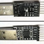
Cheapie with DTR hack
The obvious drawback was that they didn’t have the universally known FTDI chip. The CP2102 provided about the same functionality, but drivers might be a little less common. Haven’t checked Linux yet, but my Win 7 box found the drivers with no problem.
One of the less obvious drawbacks is that the connector pinout is different from “standard”. Of course it’s male instead of female, but they’re in the wrong order as well. Fortunately, that can be worked around.
Another less obvious drawback is that they didn’t choose to bring DTR out. (They did bring the chip’s Reset line out – why??) The impact of no DTR has to do with the fact that the Arduino IDE/FTDI cable system is cleverly arranged so when the IDE pulses DTR, it bounces the ATMega RST line and resets the processor – invoking the bootloader. This is important when downloading a sketch to the Arduino. If the cable system doesn’t do the reset, you have to be watching and reset the Arduino manually immediately after the compile is done or it won’t start downloading.
I looked at the datasheet, and sure enough the chip does support DTR. Maybe I can just connect to that pin and bring it out on the header. Unfortunately, the pin it comes out on goes nowhere, so I couldn’t pick up the trace on the board. But with some careful soldering, I got a very thin wire soldered to the pin itself. And after tracing the board out a bit, I found I could reuse the dumb Reset pin on the header by just cutting 2 traces and soldering the other end of my wire to a comfortably large pad (the end of the old Reset pullup resistor). You can see the wire in the picture above.

Cheapie with custom cable
Of course the connector gender and pinout are still wrong. But a custom cable fixed that. I tried it out and Arduino downloads work exactly as they should. The labeling is a coat of white-out (correction fluid) on the connector and extra-fine point Sharpie.
A much less obvious very positive feature of the CP2102 is that it has an on-board 3.3V regulator. This really saved me for a while and let me do some testing of the Educube IR boards until a supply of real regulators came in. You can see the long flying lead with 3.3V taped back down to the cable. That wire was soldered on to an IR board to power it for a while. Very helpful.

Second adapter
Now until the displays come in and boards get made, the Educubes only output is via serial to the IDE serial monitor. Figuring we’d need more cables, I took my DTR hack to the second adapter, and this time removed the header and attached a new cable directly. Looks good and works well and is a little more user-friendly.
Overall, I’m pleased with these (as I have been with almost all my cheap Chinese electronics purchases). And the price was certainly right. Unless you count the cost of my labor figuring out the DTR hack, modifying the boards, and making the custom cables. I don’t want to figure that one out.
 Update 1/3/12: I bought some more similar adapters, this time for ~$3 each. These have LEDs for data as well as power. I’m completely comfortable with CP2102-based adapters, as the drivers are very available. I’m disappointed that they don’t bring DTR out, but floored that they felt the need to bring the chip’s reset line out! This version was even stranger on the reset: the external pin goes thru a 2K resistor to the chip’s reset line. No pullup. Huh? Anyway, that made the DTR hack even easier: remove the resistor to get a nice pad to solder to, and no traces to cut. I found some nice blue wire wrap wire whose insulation doesn’t melt as you solder to it.
I had to remove the male header on these, too. This time I used a short piece of #12 solid wire and a bunch of solder to melt all the pins at the same time. (See pic in 2/2/12 update.) Worked out quite well. The cable I used on the first one was too fat and stiff. I went back to ribbon cable for the other two. I did bring the 3.3V output out as a flying lead just in case I ever need it.
One thing I didn’t realize about 2102s until now: That 3.3V regulator is not just for powering external stuff – it’s used internally, so the external logic levels it uses are 3.3V. And the max input voltage looks like it can handle 5V TTL inputs as well. So as I read it, it should talk to either 5V or 3.3V devices. Cool.
I did get slightly burned on this one, though. They reversed the TX and RX labels on the silk screen! It took a little while and chasing traces on the board to troubleshoot that and convince myself they’d screwed up. But after the first one, it’s easy to get the cable right the first time. Looking at the original Ebay post, there’s an extra pinout diagram – but it’s even more wrong than the silk screen. I was sufficiently offended that I even sent a note to the Ebay vendor. I almost wonder if these were the result of some board layout student’s first attempt. At least the price was great!
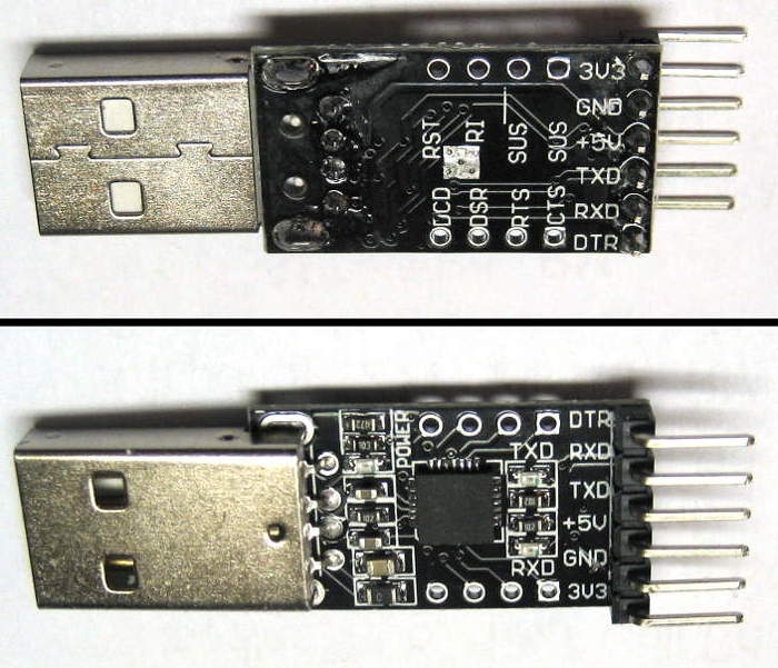
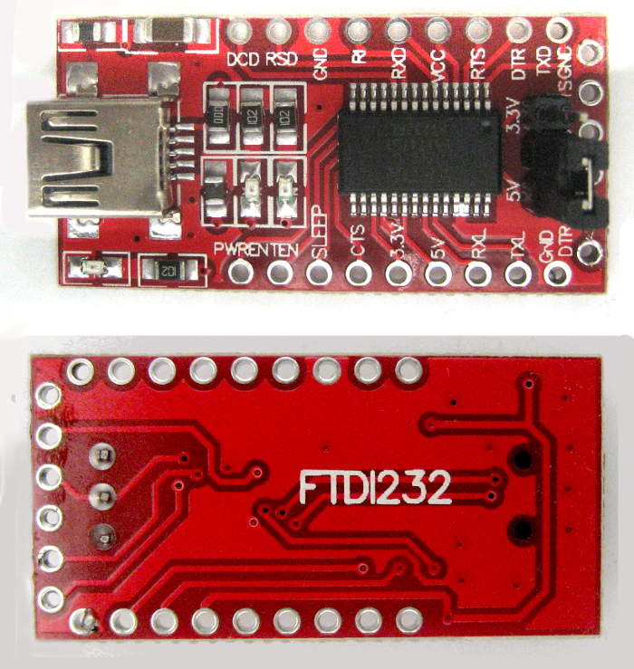
 Update 2/2/12: Here’s some exciting news in the exciting USB-TTL adapter scene: There’s a better CP2102 adapter available! Until now there hasn’t been much reason to choose one adapter over another – and there are lots of these Chinese cheapies to choose from. But this one is a little different: The extra holes along the edges break out many other signal lines – including DTR! No more soldering to a tiny pin on the chip!
I just received this one – for $2.88/free shipping. They didn’t include a picture of the back in the Ebay ad, so finding DTR broken out was a pleasant surprise. My hack to this one was a little different, too: I put a switch on to select sourcing 5V or 3.3V to the connected device.
 The first step was to remove the male header. I used my “chunk of #12 solid and extra solder” technique to heat all the pins at once. A temperature controlled iron provided plenty of heat for the job. The header pulled out intact in a few seconds, and a solder sucker cleared the holes one at a time.
The next decision was how to use the holes from the old header to provide the usual Gnd, Tx, Rx, DTR and power to my ribbon cable. I also needed to pick up both 3.3V and 5V for the switch. Both voltages appeared on the original header, with 5V going thru what I assume is a fuse (marked F1, near the 5V pin). Unsoldering the fuse provides two nice pads – one connected to the old 5V header pin, the other actually providing 5V. I used the former to connect the output of my switch to the cable and the latter as the 5V source for the switch. I took 3.3V from the original header hole – and didn’t connect that one to the ribbon cable.
 The useless original RST header hole will be repurposed for DTR, but first needs to be isolated from the CP2102’s Reset line. A quick inspection of the traces showed a single cut on the back of the board would do that. I considered just running that last line from the ribbon directly to the DTR hole, saving the trace cut and one extra wire on top of the board. That would have worked fine, but using the RST hole seemed slightly more mechanically robust.
Spooked by incorrect silk screen legends on other cheapies, I checked this time by both following the traces and a quick test with a terminal emulator and a logic probe. Sure enough, the legend is backwards on this device. Fine – that’s easy enough to fix when I terminate the other end of the cable. I’m guessing whatever amateurs lay these things out (students?) just don’t know that the convention is to label lines like Tx and Rx from the point of view of the device they’re on rather than what they connect to on some other device.
 I slobbered hot melt on the adapter and plunked the roughed-up side of the switch into it. A little careful soldering of the nice wire wrap wire I found whose insulation doesn’t melt much and it was about done. You can see where the fuse I removed was. I’ll probably cover all the wires with some more hot-melt to keep them from getting caught on things.
If you just wanted a simple USB-TTL adapter with a single supply voltage (pick either one), the only hack you’d need with this one is unsoldering the header and soldering in your cable. That’s about as clean as it gets.
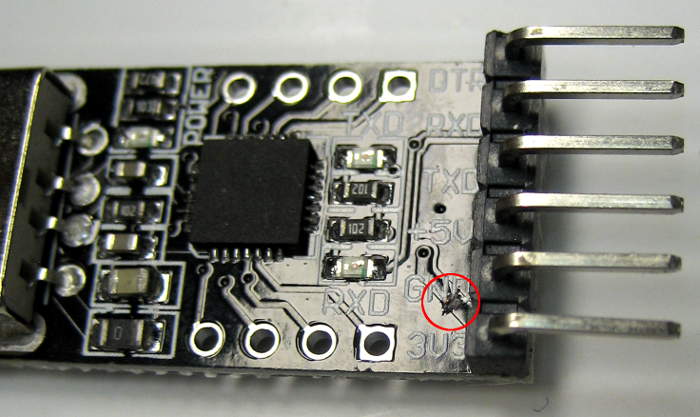
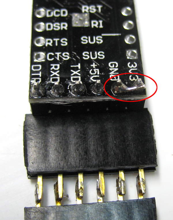
 Update 1/2/18: I just got 3 of a new version ($1.50 each), probably motivated to make a dedicated cable/adapter for the Drawbot. Pinout is almost standard, but the end pin – marked 3V3 – should have ground.
A potential hack to somehow use the existing pins would be to cut 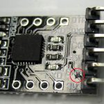 the trace to 3.3V and solder bridge that pin to its neighbor Gnd. Looks like cutting the diagonal trace on the top surface of the board should work, and a quick test seems
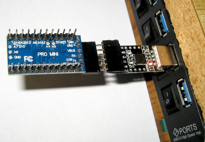
 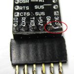 to confirm that. Jumpered end (old 3.3V) and Gnd, made up a F-F header and plugged it into a Pro Mini. It worked – at least in that board.
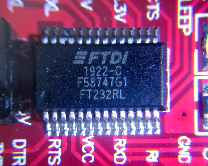
Update 4-10-20 New red boards
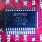 I just got 5 new red counterfeit FTDI boards. The two I checked both had serial # A50285BI, a known common fake number. The chips are clearly illegally marked to look like real FTDI.
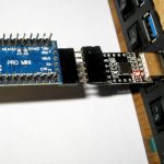
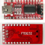 The good news is that they have a 6 pin header that’s actually in the same order as Pro Mini or Diavolinos. It still comes with a male header, but adding solder with a piece of #14 wire the width of the pins allowed me to unsolder the header very easily. It now has a female header, with the DTR end marked green.
The board also has a 5V/3.3V jumper – nice! And yes, it shifts both Vcc provided to the Arduino (or whatever) and the logic levels. All the pins of interest are broken out along the sides, and there are LEDs for TX and RX. So it’s about the nicest board I’ve come across. (Assuming you can accept the counterfeit chip and don’t have the 2.12 FTDI driver that bricks chips.)
The driver for getting a few more of these was to have a module I could add to convert an onboard serial to USB. Don’t remember which one. 🙂


