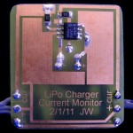
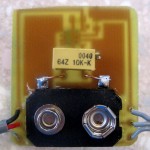
Output amp daughterboard for recording preamp

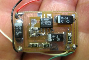
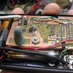
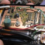
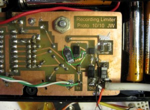
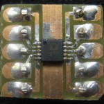
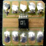
Board 30 mins after printing artwork

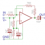
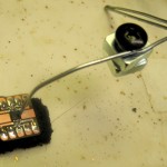
Here’s the small board that will implement the extra output amplifier to have the black prototype recording preamp/AGC/limiter thing put out enough that it works with the iRiver T30 recorder without the dumb empty files.

I did go with the tiny trimpot for the feedback resistor, so I can make further adjustments if needed.

It took about 40 minutes from printing the artwork to ready to solder, and another half hour to ready-to-test.  (It looks like I was a little aggressive rounding the corners on the belt sander, and I left the part center-marks turned on in the board layout.)   Unfortunately, testing wasn’t as smooth as I would have liked.  But I learned a lot 😕

Problems, problems, problems   Learning opportunities

I hope I learn something from this one:  The LM358 is a very old part.  I had no business assuming its output would be rail-to-rail, but I did.  As soon as I got the amp working, I saw very asymmetric clipping on positive peaks of test sine waves.  That finally made me check the specs and learn that the 358’s output voltage swing is about ground (good) to 1.5V below V+ (not so good).  In the +/- 15V supplies of olden days, losing 1.5V isn’t much.  But when you’re running on 3V and need the biggest swing you can get, it’s critical!  Yeah, there might be a 3V, rail-to-rail part with the same pinout, but I can’t get one soon enough.  Rats.

When I first tried the board, it just didn’t work.  (I still don’t understand all the problems, but the bad pot as feedback resistor – see below – was one critical one.)  But eventually it started amplifying, and I moved on to figure out how much gain I needed.

The calibration plan wasn’t too hard:

  • Run the amp up at 3V (design minimum) and put a 1KHz sine wave thru it to determine max peak-peak voltage I can get.
  • Take a 1KHz sine wave at known amplitude and record it – probably to the “good” recorder.
  • Record classical music (large dynamic range) at a couple of levels from pretty low to pretty high (thus well into limiting). I don’t care about the exact levels, and it’s hard to measure music audio levels anyway.
  • Look at the recordings.  Using the known P-P sine wave, get a voltage to Goldwave scale calibration.  Scan all the music recordings for absolute peak.  Get a peak voltage reading from that.  Now I know worst case peak voltage for audio.
  • Compute gain of amp to boost peak audio observed to just shy of max P-P capability of the amp at 3V supply.  Use standard op-amp model to compute feedback resistor.

A 1KHz sine wave at 0.2VRMS into the recorder produced waveforms on GoldWave of 0.2 units peak (not P-P).  So that’s 0.56VPP in -> 0.2 units P in GW, or 2.8VPP/GWunit.

In a loud section at maybe 4LEDs on the black proto, the recording showed a peak of 0.15 units P.  In a loud section with gain on the proto cranked all the way up and only last LED on – there was a peak of 0.32units.  So it looks like the black amp is currently able to put out peaks of at least 0.32*2.8=0.9VPP.

Unfortunately, after losing a good volt (the spec was conservative) of P-P swing, I can barely get gain of 2 out of the amp!  Much wailing and gnashing of teeth later, I decided to run the amp on 9V, which gives me 7+ volts of swing, enough to run the dumb T30 successfully (I think).  But it means I can’t fit it in the original black box, and it will require an additional piece of junk and wires on the table when I’m recording.  Ugly.

Before coming to that conclusion, I cast desperately for alternatives.  I recalled that I’d put a 5.6K resistor in series with the output of the black proto to guarantee being in spec with the “>5K output load” spec of the 2167.  The input impedance of the 790 recorder is 1.8K/channel (recording or not – so I only connect to one channel).  If the T30 is similar, I’m losing a lot of precious signal across that 5.6K.  The T30 turns out to be about 10K per channel.  If I record to both channels, that meets the required load impedance, and I can get rid of the resistor and pick up a little more signal!  I pulled the 5.6K.  Yeah, that’s building in a dependence on a specific recorder, but I’m getting desperate.

Another alternative was whether I should just accept the fact that I can only record at a much lower level than I’d like.  I always do a cleanup pass on the recordings anyway, and normalizing the level is part of that.  Is the puny signal I can get out of the black proto at least enough that when I crank it up after the fact I get a not-too-noisy result?  The limiting factor is that I must set the record level on the T30 at 21 (out of 31) to avoid the empty files.  (I get reasonable recorded level setting it at 29).  So I did a test recording (now with the small boost of the removed 5.6K resistor) at level 21.  Nothing – no recording at all.  It doesn’t matter whether the S/N ratio would still be acceptable – that signal level isn’t enough to trigger the T30 to start recording!  I still need more signal.  (It also looks like the trigger level is the average of both channels, so trying to save a little by recording only one channel just makes it that much harder to trigger.)

Another possibility is using a transformer on the output.  The 2167’s output load is still limited to 5K, and that’s about what I have to drive, so a transformer doesn’t help there.  But if I ran the new amp at 3V and even if I got hardly any voltage gain, I would get a much lower output impedance, and thus a power gain.  That could drive a transformer to give me more output voltage to the recorder.  That’s not off the table, but it would obviously significantly increase the current consumption of the amp.  I was pleased that it only drew ~0.5mA – I can afford that.  But I guess I’ve gotta pay for the signal I need somehow.  Do I have a suitable transformer?  How would it affect fidelity?  And, of course, it wouldn’t fit in the existing box 🙁

I tried a couple of the small audio transformers I had around.  An 8ohm-1Kohm gave the biggest boost, but I could still only get about 1.5V P-P out of it without distortion at 3V compared to 5V P-P from the amp alone with a used-9V 7.5V supply.  I guess running the amp on a 9V is the way to go.

NOT a pot!

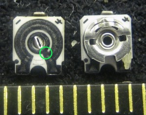
Damn.  This one cost me hours.  What I thought were 50K trimpots and used for the op-amp feedback resistor were in fact 100K variable resistors, with the slider internally tied to one end.  I only needed a variable resistor, but Murphy caused me to lay out the board to use the slider and the end it was tied to, resulting in a near-zero ohm resistor.  Of course the amp just didn’t work at all.  I finally took it off (thank goodness for the hot air!) and tacked on wire leads to another pot – and it worked fine.  There had been a series of problems, and after it was all working reasonably, I soldered (what I thought was) a pot back on.  Stopped working again, of course.  I hot aired it off again and started to look at it more closely.  (That was also when I learned the value was not as marked.)  It’s tiny – ~3mm wide – and really hard to get meter leads on reliably, but I finally came to believe the slider was tied to one end.  I cut one apart – and sure enough, it was (green circle). That one cost me a lot.

I found a way to reorient the non-pot on the pads on the board to connect to the right places, so I put it back in.  Connected correctly, it works 🙂  I carefully set it for gain of 5, set the power supply for ~8V and ran some classical music through the proto into the amp.  I saw significantly visible clipping on the scope.  I could get less clipping by increasing the supply to ~12V, but that’s not the voltage I have available, so it didn’t count, and I went back to 8V.  I don’t understand everything that went on, but I adjusted the gain (thank goodness I had the trimmer!) so there was no clipping.  When I measured it – the gain was 2.5!  A separate box and battery and all it buys me is a lousy gain of 2.5!  I did an end to end test through the proto (adjusted to 5-6 LEDs, about what I think it should be) and to the T30 at rec level of 21, playing both some classical music and some square dance calling.  The recording was clean – no audible distortion, and at about the level I usually get with my “good” setup (around -23 dB).  I found a little project box that looks like it will fit, so I’ll put it all together.

Output amp

So – I end up with an amp that works, but needs its own 9V battery and a new box. (And a switch and a jack and a cable with a plug.) At least with the 0.5mA current draw, the ~500mAhr of a typical 9V will give a couple of weekends’ battery life.

I’m sort of up against physics – it’s hard to get a very big signal that won’t clip on a 3V supply – and the annoying characteristics of the T30 recorder. So my goal of producing a fairly simple design that I can reproduce at will that’s recorder-hardware-agnostic will be a bigger challenge than I thought. More on the grand project to follow, but at least I think I’ll have something I can use for next weekend.

Just to be honest with myself: The only thing this whole additional amp nonsense bought me was a workaround for the design flaw in the T30 that caused extra empty files. Just because I got a couple on Ebay before I found out about the problem doesn’t mean I should go to huge efforts to make them work. Better to cut my losses and find better recorders.

Update 2/14

The good news is that I’ve saved all the effort of building an enclosure for the little output amp, as I don’t seem to need it after all for two separate reasons.

All my previous reports and tests have been with my red 1GB T30.  I also bought a 512MB silver one on Ebay.  I just tried that one to see whether it exhibits the empty file retrigger behavior at high record volumes.  It doesn’t!  Even with rec level at 31 (max) after one file is closed for timeout of quiet, it sits there just like it should, waiting for input before starting the next file.  That means I can use that one with the black preamp and no extra output amp and get both no empty files and ideal record level.  The one down side is that since it doesn’t support mono recording, it burns thru its 512MB in  about the same time as the 790 fills its 256MB.  But that 4+ hours is still plenty for any single session.

I misreported that the red T30 uses the average of levels in the two channels to decide when to trigger a recording, and that the signal level from the black proto wasn’t enough to trigger recording at record level 21.  It turns out it uses only one channel to trigger recording – and it apparently wasn’t the channel I was using.  When I drive both channels (or even the one – ring – it uses), it triggers reliably at rec level 21.  The recorded level is considerably lower than I’d like, but when normalized still sounds just fine.  That means I can use the red T30 without the new little amp.  It’s 1GB, and so even wasting half its memory on stereo, it still records about twice as long as my good 790s.

I’m still unclear on how I came to the wrong conclusion about the channels.  I only record one channel (ring) on my 790s, so I set the black proto up to do the same.  Testing the two channels separately shows it’s the ring that is used to trigger recording.  So I don’t know why it didn’t work before.  I am driving both channels now, but specific tests show that’s not necessary to trigger.  I just don’t get it.

But it seems to work.  I’ll do tests with both T30s and the black proto at a dance tonight (as well as my good 790 to make sure I get a good recording).

Last update

Nice try!

The recordings from the dance were all completely acceptable.  I did some with the red one and got low record levels (as expected from setting at 20), but undistorted and completely recoverable.  After I switched to the silver one, I got a couple of recordings at excellent level (and undistorted) – but the empty files were there on that one, too!  I cranked the level back to 20, and got all subsequent recordings at expected low but acceptable level, and no empty files.  So the empty file phenomenon is not limited to the red one, but I can still live with the results.

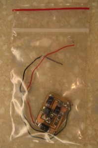
The little amp that was going to save the world and make recording possible is now relegated to a little plastic bag, hoping it finds some new use someday.

Posted in Recording preamp/limiter | Leave a comment

Output amp for recording preamp?

A 358 on a board

I may have been wrong about not being able to put an output stage in the prototype recording preamp before the weekend coming up Feb 18-20 in Washington DC. While I don’t have time to redo the whole board, including all the assembly and fitting it into the case, it’s just a prototype, so a hack is allowed. Maybe I can squeeze a little daughterboard in with the amp!  It will all be SMT, and just 4 wires (power, ground, in, out). But would another little board fit in the case?

Before

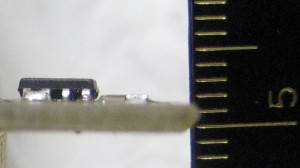
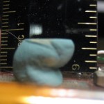
A board with an SMT LM358 is maybe 3.5mm high. Next question: how much clearance is there between the existing board and the top of the case? How do I measure a space inside a closed case? Clay. I rolled a little post out of gray-green clay much higher than the distance to the inside of the case top and stuck it on the board.  Then I closed the case on it, smushing it down.  Wow – there’s a fair amount of clearance.  Looks like a good 8mm.

Smushed down

I should be able to fit another board in there with no trouble! The chip output is nominally 320mV RMS (and my attenuated output should be half of that), but I’m not sure what the real max peak-peak signal is. The supply is only 3V, so I’ll never get more than that out of the amp, so the gain isn’t going to be more than maybe 5 or 6?.  Off to Eagle to lay out the amplifier stage!  Well, actually off to bed – gotta go to work tomorrow.  This work thing is totally getting in the way of my projects. 🙁

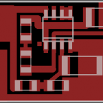
Update on output amp daughterboard Daughterboard 1.0"x0.625"

Output amp

I’ll use the breadboard to determine feedback resistor value.  I laid out two 1206s in series, figuring surely I can come up with a combo that will be close to what I need.  I’ll move the 5.6K in series with the output of the 2167 from where it’s squeezed onto the main board (you can just see it in the picture in the previous post with the green line around the R/C hack) to the daughterboard as the input to the opamp and use where its ends were – the output cap and the white wire in the output cable – to be the input and output connections to the daughterboard.  V+ and ground are easy.  Biasing the non-inverting input to V+/2 should allow max output swing assuming the 358 will get close to rail-to-rail output.  Board layout is complete (unless I swap the two feedback resistors for a 50K SMT trimpot I just found).  Getting closer!

Posted in Recording preamp/limiter | Leave a comment

Recording preamp: I think I won!

Hack to chip

The problem all along has been that the output of the preamp/AGC/limiter chip was clipping – being overdriven.  Now in a reasonable chip whose job is to prevent distortion, we would really hope the designers wouldn’t overdrive the amplifier on the chip.  But apparently that’s just what happened between the SSM2165 chip I have had great success with and its replacement 2167.  I chased several other paths to see why this was happening – maybe the AGC cap was too big and it couldn’t attack fast enough, maybe the compression ratio or noise gate level were inappropriate, maybe the LED level meter wasn’t calibrated right and I was just driving it way too hard.  But nothing seemed to help.  (Well, except for increasing the supply voltage.  But that had limitations, too 🙁 )

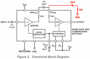
The device has a level detector that puts out a DC voltage proportional to the input signal amplitude.  That DC voltage goes to a Voltage Controlled Amplifier to decrease its gain as the input level increases (and vice versa).  The two resistors and cap at the bottom give the user some control over the details but basically the device tries to provide fairly constant output for widely varying input levels.  At fairly low input levels, this works as designed.

Unfortunately, for music with a good dynamic range, at mid and higher levels, the VCA can’t handle the peaks of the signal, and it clips – which is a Very Bad Thing, and I would argue, a design flaw.

Fortunately, the designers brought the audio out – normally just to be fed back into the VCA.  (There are DC level differences between the output of the first buffer amp and the input to the VCA, necessitating a cap to connect them.)  But that exposure to the signal, plus the 1K resistor they thoughtfully provided on the output of the buffer amp allowed me to decrease the level to the VCA by making a voltage divider to ground.  There’s DC involved, so I needed a cap as well as a resistor.  I chose 1K to cut the signal about in half.  The diagram shows my hack in red.  (I looked for Application Notes for the chip, but found nothing about using the access to the signal to protect the VCA from being overdriven.  If I can summon the gumption, I’ll write to the company and ask about it.)

I ran tests on the breadboard with and without the signal attenuator, both to an amp/speaker to listen to and to a known good recorder so I could analyze the output more objectively.  It worked!  I could get dramatically greater dynamic range with no distortion.  Of course the output signal level was half of what it had been, but that’s a necessary price to pay for the device not clipping.

Resistor and cap hacked in

After making a baseline recording, I added the cap and resistor to the PCB in the existing device (in green), and made another recording.  Greatly improved!  I will have to adjust the recording level to make up for the lower output signal level, but that’s a quick test and adjustment.  Of course “the test is the test”, so I’ll bring it to a dance Monday night and run it in parallel with my very reliable good recording setup.  I’m guessing the results of the two will be indistinguishable.

Update later that night

I recorded the dance with the new prototype preamp/AGC/limiter thing, using a known good IFP-790 and the T30, each for half the dance.  (That was in addition to my “good” preamp and IFP-790 just in case.)  I’ve uploaded it all and listened to most of the tracks on both recorders driven by the proto preamp.  Audio quality on all the tracks was perfect!  (All were perfect on the “good” setup too, but that’s always perfect.)

So I will declare:  I have indeed won the battle of getting rid of the distortion on the proto with the new 2167 chip.

There’s still an issue with the T30 recorder, though:  As with the IFP-790, the T30 has an “auto sync” feature that starts recording when the signal exceeds some threshold, and stops after several seconds below the threshold.  There’s apparently a switching transient at the end of each file, and when I crank the record volume up almost all the way so it gives excellent recorded level from the reduced output of the proto, after each file ends, the transient fires another recording file.  So the recorder is littered with dozens of 9 second almost empty files.  They’re easy enough to filter through by file size, but they’re annoying and waste memory and battery.  I’m pretty sure I recall that when the recording volume setting is lower, the transient isn’t enough to trigger a new file, so the auto start-stop gives just what it should.  For production versions of the preamp, I should probably put a little ultra low power FET amp as an output stage so I get high enough level out that I don’t have to crank the record volume up so high, avoiding the tiny useless files.  Probably won’t happen in time for the weekend coming up later this month, but in the next version…

Update on SSM2167:

I (created a login on the site and) posted a question to “Ask an Engineer” on the Analog Devices site asking if they’d heard complaints about clipping in the 2167 VCA.  I got a nice prompt email reply saying they were sorry but their forum only had sections to discuss their cutting edge DSP chips.  !?  Oh well, I tried…

Posted in Recording preamp/limiter | 1 Comment

Recording preamp yak shaving

New attenuator

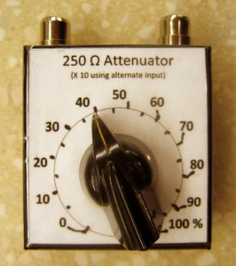
All I wanted to do was make some quantitative tests on the breadboarded AGC chip.  I don’t have any calibrated audio equipment, so I thought it would be nice to have one calibrated attenuator.  Nothing fancy – just a pot with a manually calibrated dial so I could apply say a fairly accurate 40mV signal.  I eventually ended up with almost exactly what I wanted.  But the path to it was long and full of yak fur.

So I started looking for a pot.  Pretty low value so the load it was driving wouldn’t affect the accuracy much – maybe 100 Ω.  Audio taper would be nice.  And no trimmers – it needs a real shaft for a real knob.  But the big jumbled box of pots collected over the years was a nightmare to search through.  Too deep, and too many unmarked pots.  So I dumped the box out and made a little circle of piles around where I was sitting (my standard sorting approach).  And I had an ohmmeter and a Sharpie and measured and marked every unmarked part.  There were a lot.

(OK, I like my dessert first, soI left the big mess on the floor while I selected a pot and made and calibrated the attenuator, only finally to come back to clean up.)

New boxes!

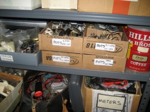
Now I had nice sorted piles of pots – 1K, 10K, 50K – what to do with them?  I cut up some of the long narrow boxes I scrounge from work (from coffee packets) that fit perfectly on 12″ deep shelves, using the space very efficiently.  I taped some dividers into them with packing tape, labeled them, and my pots had new homes!

By cutting the boxes in half, I have nice shallow storage that makes it easy to see what I have.  I guess from a dimensionless view, the appropriate depth of a container to root around in is not more than twice the “size” of the objects it contains.  That works as well for pots as for nuts and bolts.

Final home

Anyway, the shallow boxes stacked nicely in the spot the old too-deep box had been, taking up the same footprint, but with an order of magnitude better organization.

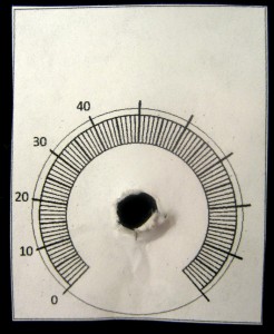
I found a little metal box for the pot, and working around the existing holes measured and drilled and made a home for the pot.  I wanted it to look kind of nice, so I’d need a label for the top.  Since I couldn’t find an audio taper, I wanted 10 marks around the circumference to show what percent of input the attenuator was giving.  I knew for it to be fairly accurate I’d need to calibrate it by hand, but hand-written numbers were uglier than I hoped for.

Dial in progress

I found an old (white on black) dial plate with about the usual 230° rotation, scanned it, photoshopped it, and pasted the image into Word, where I made a bunch of text boxes for the numbers.  The actual dial marks would be misleading, as they almost certainly wouldn’t line up with the manual calibration I would do.  So I only used it to let me locate the text boxes in approximately the right places, then deleted or hid the image.   I took too-great pains trying to get the numbers in the right place.  The final calibration missed the numbers by a visible amount.  But what I really cared about was accurate calibration, and the numbers were close enough to be obvious which hand-made mark they go with.  In hindsight, I should have stuck a piece of paper on the box, done an initial calibration run marking the main points, then scanned that and used it to locate the text boxes with the numbers.  I wonder if I’ll be clever enough to do it that way the next time.  After calibrating it, I put a piece of 2″ clear packing tape over the whole thing to make it look shiny and stay cleaner.

The other tool I added to my audio test collection was an old Palm Treo phone.  I’ve wanted an easy, reliable audio source on the bench for a long time.  I have a cassette plus FM Walkman,  but tapes are a hassle and FM reception isn’t great in the basement and the wall wart to power it is a nuisance.

Audio test waveform

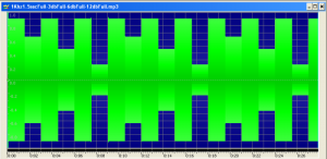
I’ve made several audio test signal MP3s, and they’re very helpful.  I’m not willing to buy a dedicated MP3 player for the bench, so I scrounge old ones lying around.  But it finally dawned on me that one of my old Palms would be happy to serve as a dedicated player.  I considered writing a signal generator app for it (since the first couple I found were not free), but I can create MP3s with GoldWave to do about anything I want, and there’s more than enough storage for them on the Palm.  So the “signal generator app” is just a playlist on the audio player app.  Works for me.

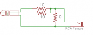
I got burned the other day with some distortion I couldn’t track down.  What I’m working on now is mono, and I was playing some music through it.  I was using an adapter with a male 3.5mm stereo plug and one RCA jack to get audio from some MP3 player.  It “combines” the two stereo channels by shorting them together.  This is not a nice thing to do to the output amps in whatever is driving it, but since it was all mono (I thought) the two channels should be putting out the same signals, so it shouldn’t be too bad.  Unfortunately, I was wrong, and the recording I was playing was indeed stereo, and with noticeably different program material on the two channels.  That means the “fighting” output channels could indeed have introduced some distortion.  Fine.  Let’s make sure that doesn’t happen again.

Safe stereo-to-mono

So I made up a “safe” adapter, with 10Ω in series with each lead, and 10 to ground, just to provide an earphone-like load.  That’s guaranteed to not abuse headphone output sections or introduce any distortion from such abuse.

So a day and several yaks later, I have my attenuator, and maybe I can start to make progress on the recording preamp again.

Posted in Recording preamp/limiter | Leave a comment

Recording preamp update

Better alignment!

The good news is that I did much better at aligning the replacement chip on the header than the original.  (That was after I blew out the first one by exceeding the absolute max supply voltage.)  It seems to distort a little less with higher supply voltage, and I wasn’t watching as I cranked it up a little higher to see if it would get even better…

I used my hot air station to remove the first one.  Worked great.

Low tech 3rd handHolding the chip in place to solder the first pin or two has been a problem.  Inspired by a great low-tech clamp Google found,  I made an even simpler one out of baling wire and a weight.  That worked very well and is a welcome addition to my SMD toolbox.

Breadboarding with the header was very helpful.  I could really see (and hear) the compression ratio changing as I changed the resistor (a pot) that controlled it, and could see/hear the noise gate (level below which signal is greatly attenuated to avoid noise during quiet times) change as I tweaked that control pot.  And I played with the “averaging cap” that controls the attack/decay characteristics of the AGC.  I had great hopes that since I had used a value greater than recommended for that cap it couldn’t respond quickly enough (delaying AGC attack) resulting in the clipping I saw.  But I never did get rid of the distortion completely.  (Or at least it didn’t look like it on the scope.)  I wanted to actually record at a known good level on a known good recorder and (listen and) look at the recorded waveforms to see if it clipped.  But then I blew out the part, and then it snowed…  I’m back in business now and still have an hour or two to play before I have to go to bed to go to work tomorrow.

Posted in Recording preamp/limiter | Leave a comment

Recording preamp/limiter rebuild

I built a new preamp/limiter from a 3V SSM2167 (with 0.5mm pin pitch) quite a few months ago.  I did a little bench testing and could hear its AGC kicking in, and though it didn’t seem as good as the previous ones based on the 5V SSM2165s, I guessed it would be fine.  Wrong.

I just went back through some of the recordings to try to recall what the problems were (since it’s hard to fix them otherwise).  The recordings it made were useable, but there was a little clipping – which is of course completely unacceptable.  The dynamic range is too small somehow.  I sort of recall trying to set the gain down to avoid the clipping and having the noise gate cut everything off way before it should have.

I used an IRiver T30 instead of my usual IFP-790 recorders, so that’s another dimension I need to get a handle on.  The T30 would only record in stereo – a waste of half its memory – but it should still be very high quality.

The header

I figured I should probably breadboard it so I can play ’til I get it right, but the tiny SMT chip doesn’t lend itself to that.  So I made up a little breakout board with 0.1″ spacing pins on 0.3″ centers, just like “normal” DIPs.  That was a challenge, and I had to define a custom 10 pin DIL header with near-zero pad on the inside of the middle pin.  I had to run some traces at 12 mils – the smallest I can reliably make.

Yeah, it’s really small, but I did an unusually poor job soldering it in.  One side is off by nearly half a pin width, and there’s a bent pin on the other side I didn’t notice until looking at the picture.  I think it’s electrically sound, but it’s pretty ugly.  It’s a good thing nobody will ever see how sloppy it was.

Wearing a magnifier, it’s not too hard to get the chip pretty well aligned on the pads.  But you have to hold it down while soldering at least the first couple of leads.  I have have to invent a spring wire that reliably pushes only exactly straight down, so I have something to hold chips down after placement.

Anyway, now I have something I can plug into a breadboard to do some more focused testing on.

Posted in Recording preamp/limiter | Leave a comment

Current sense amp for camera battery charger

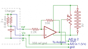
I had another board I needed to make, so I laid out a quickie for an LM358 based amp to let me measure current while charging Canon camera batteries with the connections I’d hacked into the charger a while ago.  I took a chance and didn’t prototype it:  I hoped I could design something with one opamp and a couple of resistors without screwing it up.

Only test so far is that I could set the ref gnd pot to null out the offset input so I get 0V between outputs to A/D channels 1 and 2 with the current sense input shorted to the “V+” input.  This is obviously battery voltage dependent,

but it won’t need to be done very many times.

The circuit is kind of strange, but I think it will work. The negative side of the camera battery goes straight thru to Arduino ground.  Battery + goes straight thru to one A/D channel so the Arduino can measure battery voltage.  Should never be > 4.2V or so, so the 5V range of Arduino input should be good.  That battery + is also connected to “ground” of the current sense amp.  Batt clip, offset nullThe current sense voltage is a small increment above V+, and gets amplified ~15 times and inverted by the opamp and is applied to the second A/D channel. The Arduino can measure that voltage (and thus compute the current) as a difference from the voltage it sees on the V+ channel.

Next step is to verify operation of the sense amp and calibrate the it.  I’ll apply say +0.2V on the current sense input with respect to “V+” in and verify I get about -3.0V on the A/D 2 pin with respect to A/D 1.   Assuming that works, I’ll adjust the calibration constant in the Arduino code (which doesn’t exist yet).  Let’s see – 0.2V across the 0.34 ohm current sense resistors is 0.588A.  So I tweak the current calib constant for indication of ~0.588A.

I guess the code will look something like this:

- init A/D ports 0,1 for input with 5V range
- #define VoltCalib  5/1024 # 1024 counts in 10 bit A/D channel
- #define CurrCalib 0.588*VoltCalib/3  # guess: 3V -> .588A
Main Loop:
read A/D chan 0
BattVolt=AD0*VoltCalib
print battery voltage
read A/D chan 1
Current=(AD0 - AD1)*CurrCalib
print current

I have more pressing projects right now (like rebuilding a recording preamp/limiter so it’s ready to go for a square dance weekend in a couple of weeks), but this one will come up again…

UPDATE A FEW MINUTES LATER ON LOOKING AT THE BOARD LAYOUT:

Damn – assumption about being able to design something this simple without screwing up was wrong.  I put the battery clip on backwards.  Fixing that is pretty simple – swap the leads.  But reversing the supply voltage to the opamp probably blew it out.  I thought everything was ready to go when I got some time to do the next steps.  Rats.

UPDATE AGAIN AN HOUR LATER…

I swapped the 9V leads and then couldn’t help myself – I checked out the amp.  Sure enough, it was completely dead.  I cut the old chip off and put a new one in.  At least I got a little more practice with surface mount repair 😕  The good news is that it does in fact amplify – and about 15X, as designed.  The bad news is that in addition to the implementation screw-up of reversed battery leads, I must have been on drugs when I thought moving the center point of the supply would let me null out the offset voltage.  Specs on a 358 showed input offset voltage of up to a couple of mV.  That’s what I was trying to null out.  Hmm – the back of the envelope says with gain of 15 that would be an error of ~0.05V.  With the calibration that 3V ->0.59A, it gives (0.05/3)*0.59, or about 10mA.  I guess that’s not as bad as I thought.  And that offset should be fairly constant, so worst case I could correct for it with an additive term in the code.  OK, that’s not so bad, though I really didn’t have an extra hour to spend on this project.

Posted in Li-ion camera battery | 1 Comment

Pusher shovel handle downside

Prisoners

I got a chuckle out of an unintended side effect of the new handle on my big pusher shovel. A small arsenal of snow removal tools lives next to the front door during snow removal season.  A couple of normal single shovels sit sometimes in front, sometimes in back of the big pusher.  But their handles always lean against the wall.  Right after I made the new handle, I propped the big shovel up against the wall in its normal spot.

But the next snow, when I tried to grab one of the little shovels – it was a prisoner!

I smiled, and chose not to remove the new bar. 🙂

Posted in Snow shovel handle | Leave a comment

Welder foot switch

Foot switch from scrap

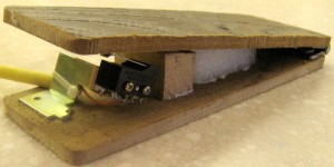
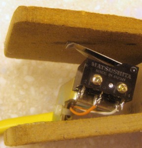
I put the foot switch together entirely from scrap.  I found 2 microswitches on a little bracket, a scrap of paneling, and old hinge, a block of wood and some closed-cell foam for a spring.  The wire is a scrap of stranded Cat 5 from a patch cable thrown away at work because the connector was broken.  A little Gorilla glue (and solder) and it was done!

Stepped switch detail

The original plan was to have significantly different spring tensions for the two switches so I could feel when the supply was off and then push harder when I wanted to fire the SCR.  But this was so simple I couldn’t resist.  I just bent the lever on one of the switches so it was guaranteed to operate before the other and called it done.  I really like the ‘elegance from scrap’ implementation.

The plan for how to shut off the supply has changed, too.  I was going to use a solid-state relay on the input to the transformer with a little always-on 12V supply driving the isolation LED through a resistor.  That would default to having the transformer on whenever it was plugged in.  The “shut off the supply” switch would just short out the LED, turning power to the transformer off.  That would leave me free to “wire-OR” some more circuitry in to sense the voltage on the cap and use the same mechanism to shut the supply off when it reached some preset value.

That would have worked fine, but I shifted to the simpler approach of just putting a power MOSFET transistor in series between the supply and the cap, arranged with a resistor from + to turn it on by default.  Again, the shut-off switch would just short the gate to ground, turning the transistor off.  That leaves me with the same wire-OR options for a voltage control, but a much simpler design.

I didn’t have a 25A MOSFET, and there’s no place local to get stuff like that except Fry’s.  They carry NTE stuff, so I found an NTE part that would work and thought for a trip to Fry’s I’d be done.  But the dumb part was $10.50!  I’ll pay for special parts when I need them, but this was just a silly pass transistor.  Electronic Goldmine had suitable parts for $1.29 or less but I’d just made an order there – grumble grumble…

Ah – how about Ebay?  You can get almost anything on Ebay, usually cheap.  The interesting lesson in this was from the fact that I didn’t want to wait a couple of weeks for nice cheap parts from China.  Most places in this country advertise their advantage over Chinese merchants by saying their stuff “ships from USA”.  So adding “USA” to the search term limits the hits to stuff you can get in a few days.  My MOSFET is on its way.  🙂

Posted in Battery Tab Welder | Leave a comment

Welder is taking shape

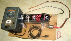
An old battery charger, re-purposed as the charging supply for the welder is rewired and functional.  With thanks to some correspondence from Bob Van Valzah, I went with the dual half-wave arrangement using the center tap to get one diode-drop more output voltage, but replaced the “ugly” old stud rectifiers with half a potted bridge.  I also went with a 1 ohm series resistor to limit the initial current surge, since the cap looks like a short circuit at the start of charging.  Thanks to Bob also for pointing out an error in the schematic of the full-wave bridge diagram in my email 🙁

The supply charges the cap to 13V in about 3 seconds, and to 16V in about 11 seconds.  That should be fine in practical use.  The quickest I can picture being ready for a second weld – repositioning the electrodes for the second of 2 pairs of spots on the same strip on the same end of the same cell – would be a few seconds.

The red/white pair is now connected so a dry contact across them will fire the SCR.  (One wire to the gate and the other through 100 ohms to + on the cap.  That avoids the battery many others use to trigger the SCR.)  And it’s all mounted to a board which may soon have a handle hole at the balance point with edges nicely rounded off by Andrew’s router.  I’m considering mounting an LED voltmeter that came on top of one of the caps to the board.  I’m not sure about that one yet, as it costs a continuous 30-90 mA.

One remaining step is making a foot switch to shut off the supply and fire the SCR.  It will have two switches mechanically staged so the one that shuts off the supply will always close before the one that fires the SCR.  The other remaining step is making the solid state relay to shut off power to the charger.

Getting closer!

Posted in Battery Tab Welder | Leave a comment