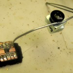
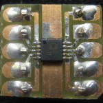
The good news is that I did much better at aligning the replacement chip on the header than the original. (That was after I blew out the first one by exceeding the absolute max supply voltage.) It seems to distort a little less with higher supply voltage, and I wasn’t watching as I cranked it up a little higher to see if it would get even better…
I used my hot air station to remove the first one. Worked great.
 Holding the chip in place to solder the first pin or two has been a problem. Inspired by a great low-tech clamp Google found, I made an even simpler one out of baling wire and a weight. That worked very well and is a welcome addition to my SMD toolbox.
Breadboarding with the header was very helpful. I could really see (and hear) the compression ratio changing as I changed the resistor (a pot) that controlled it, and could see/hear the noise gate (level below which signal is greatly attenuated to avoid noise during quiet times) change as I tweaked that control pot. And I played with the “averaging cap” that controls the attack/decay characteristics of the AGC. I had great hopes that since I had used a value greater than recommended for that cap it couldn’t respond quickly enough (delaying AGC attack) resulting in the clipping I saw. But I never did get rid of the distortion completely. (Or at least it didn’t look like it on the scope.) I wanted to actually record at a known good level on a known good recorder and (listen and) look at the recorded waveforms to see if it clipped. But then I blew out the part, and then it snowed… I’m back in business now and still have an hour or two to play before I have to go to bed to go to work tomorrow.

