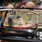
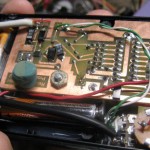
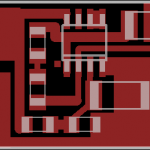
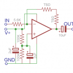
I may have been wrong about not being able to put an output stage in the prototype recording preamp before the weekend coming up Feb 18-20 in Washington DC. While I don’t have time to redo the whole board, including all the assembly and fitting it into the case, it’s just a prototype, so a hack is allowed. Maybe I can squeeze a little daughterboard in with the amp! It will all be SMT, and just 4 wires (power, ground, in, out). But would another little board fit in the case?
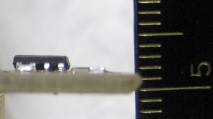
A board with an SMT LM358 is maybe 3.5mm high. Next question: how much clearance is there between the existing board and the top of the case? How do I measure a space inside a closed case? Clay. I rolled a little post out of gray-green clay much higher than the distance to the inside of the case top and stuck it on the board. Then I closed the case on it, smushing it down. Wow – there’s a fair amount of clearance. Looks like a good 8mm.
I should be able to fit another board in there with no trouble! 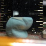 The chip output is nominally 320mV RMS (and my attenuated output should be half of that), but I’m not sure what the real max peak-peak signal is. The supply is only 3V, so I’ll never get more than that out of the amp, so the gain isn’t going to be more than maybe 5 or 6?. Off to Eagle to lay out the amplifier stage! Well, actually off to bed – gotta go to work tomorrow. This work thing is totally getting in the way of my projects. 🙁

