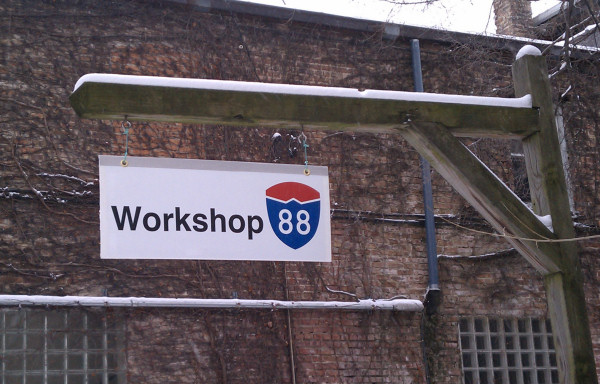
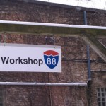
It’s done! I’m delighted and relieved to have the sign installed and operational. Here are some final notes about the construction techniques and challenges. (I promise not to whine any more about design decisions.)
-
-
Jan 2011
-
-
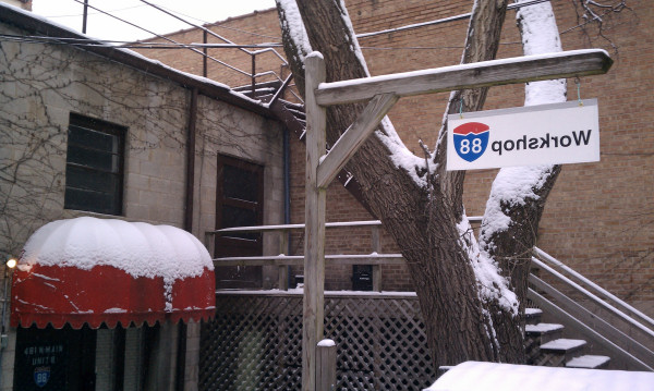
From the back
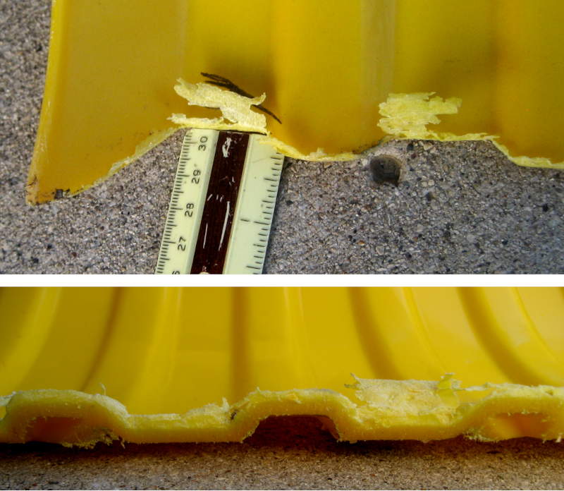
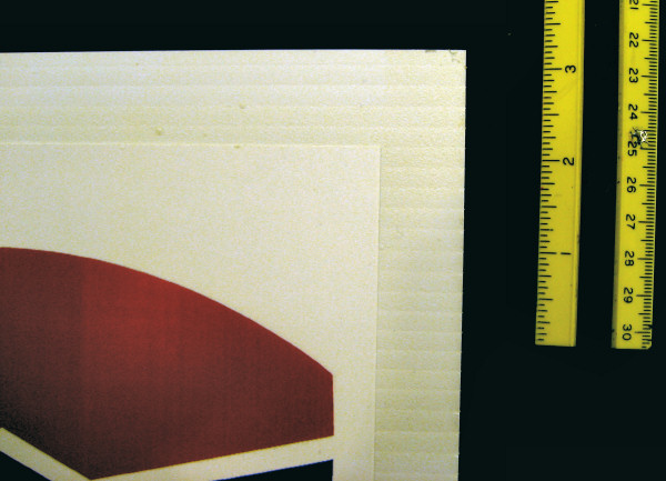
The test scrap

Test scrap
I dragged my feet at making a test piece, since it was extra work and extra time
to dry, etc. But that test scrap was truly my friend. I tried both papers with both adhesives, and after destructive testing came to believe the 3M #77 adhesive was better than the Elmer’s. The HP paper also stuck better than the other. Based on that, I decided to use the HP/3M combo for the front side of the sign so it would have the best chance of surviving for a while.
(There’s also a 3M #90 spray adhesive which is supposed to be even stronger than the #77.)
I also tried the overcoat spray on the test scrap – including spraying over dried adhesive overspray, and was discouraged that it gave a very rough finish and tended to lift the Adventure paper. That led me to prefer polyurethane instead.
That scrap gave me something to play with the aluminum channel on as well. And something to try my sharpened grommet on. It reinforced what I already knew: Always test/do dry runs first!
Glueing

Glues
The spray adhesives I used to attach the waterproof “paper” panels to the plastic backing are contact adhesives – which means I had only one chance to get each of the 4 panels on each side in perfect alignment with each other and the backing. I chose to tape the panels together so I could get their relative alignment right without fighting contact adhesive. That meant however, that while I only had one sheet to align on the backing, it was a very large one.

Clothespin stops
The first very valuable simplifier was from an idea from Lauren. I cut the noses off square on two wooden clothespins and clipped them on the bottom of the plastic to provide a physical stop to locate the bottom edge of the big panel of panels. One whole dimension got almost trivial! I had some marks on the panel and backing so I could locate the panel accurately from left to right before allowing it to touch down.
The first problem with handling the 11″x29″ panel was that it was floppy: I held the outside edges quite near the bottom, which gave me good control in touching the stops and moving it left and right. But (discovered in dry runs – ALWAYS do dry runs on something like this!) the top half just flopped down and would touch the adhesive long before I was ready. Lauren to the rescue on the first panel: She held the top half up while I aligned the bottom. When the bottom was in its final resting place, we were free to roll the rest of the panel down. Worked fine.

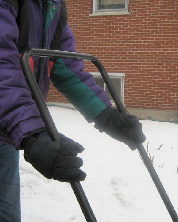
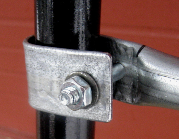
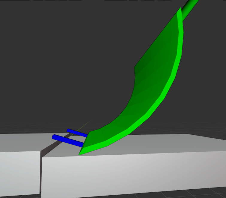
Stands for the stick
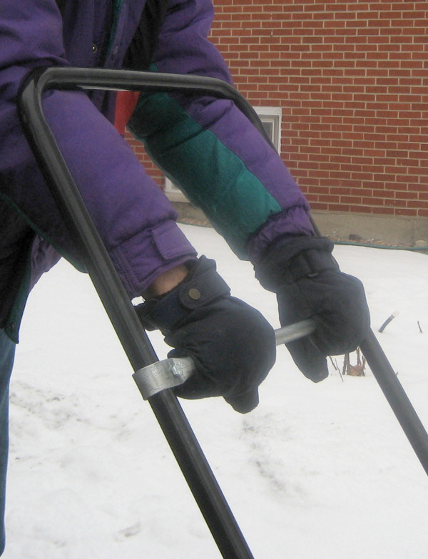
But I glued the second (back) panel on by myself. How could I keep the top half off the glue? I taped a stick – wider than the whole sign – near the top of the panel. By shaping a couple of 3″ high stands out of baling wire, I had rests the stick could sit on to keep the top of the panel safe while I started the bottom. Of course I still had to keep the bottom from sticking while I messed with the stick. You can see the blue tape tail extending over the bottom edge of the sign I held in my mouth to manage the bottom while I put the sticks in the rests. After that my hands were free to grab the bottom corners (I dropped the tape tail from my mouth) and I aligned the bottom and let it touch down.

Taped panels, stick, tail
Then I picked the stick off the stands, knocked them out of the way, and rolled the top half down, stick and all. That worked fairly well too, thanks to a couple of dry runs.
The first panel – the front of the sign – was printed on the HP laser “paper”. It was really thin plastic sheet. While you can deform it a little if you try to tear it between your fingers, it’s really pretty stable, and doesn’t stretch much at all.
The second panel – for the back – was the “Adventure paper”. That’s a really different material. It stretches and deforms MUCH more easily than the HP stuff. That stretchiness showed up as I applied the second panel. As I aligned it for final placement, I was holding it near the bottom corners, and pulling fairly hard to keep it taught and off the adhesive on the backing. That seemed to work OK, but as I was smoothing the top half down, there seemed to be a pucker – too much material – in the middle. I was able to smooth it out fairly well (since it compressed as well as stretched), but I didn’t understand what had happened until I looked carefully at the bottom edge. It didn’t match the bottom of the plastic very well – because it was curved! My pulling to keep it tight had stretched the bottom edges of all the panels. (The tape held very well.) That resulted in the lump in the middle. Quite a surprise – and just would never happen with the HP stuff. I did get it all smoothed out though.
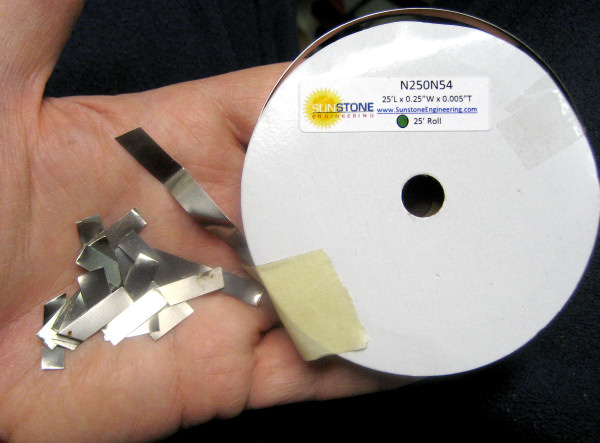
Top channel

Aluminum channel scrap
To provide protection from water seeping in under the top edges of the panels, and to help hold those edges down if they did start to peel away from the backing, I made an upside down U-shaped channel from some 0.004″ aluminum sheet salvaged from the tops of 12″x20″ trays of catered in lunch stuffs from the office. (I just grabbed a couple of the tops. After working with the material, I find it valuable enough that I’d even consider going into the kitchen in the evening before the cleaning crew arrives and dumping the leftover whatever into the garbage and washing the whole trays to bring home!)
I cut strips wide enough to cover maybe the top 1/4″ of the panels on both sides (plus the 4mm thickness of the plastic backing). I couldn’t get a 30″ strip out of what I had, so I made 2 strips and butted them together. I used a wallpaper seam roller on the very smooth solid surface counter in the kitchen and got them quite smooth. Obliterating lettering pressed into the aluminum that way was fairly easy. Despite very careful measuring and using a 24″ steel square as a sort of bending brake, I had a very hard time getting the bends where I wanted them. I had to do more touchup trimming than I expected.
I roughed up the side that was to glue to the sign thoroughly with coarse sandpaper. My first thought was to use Gorilla glue to attach it, since that sets up fairly waterproof. But when I did a test on my scrap piece, I realized I couldn’t control the expanding glue well enough to keep from messing up the visible parts of the panels. The channel isn’t really under much physical stress, so I went with spray adhesive. I chose the 3M #77 adhesive, since it seems to be stronger than the Elmer’s spray stuff.
Before spraying, I masked one whole side of the sign up to about 1/8″ from the top of the panels. Since the channel should overlap the panel by 1/4″, that left the outermost edge of the channel with only the adhesive sprayed on the channel itself. But it kept me from having to try to mask to precisely where the channel (once bent down) would hit the panels. I opened the channel to about 90°, taped it to the back of the sign in its final position, and sprayed the adhesive into the V formed by the unmasked top of the sign and the channel. Then I peeled the masking off (since the masking tape would be under the edge of the channel) and carefully bent the channel into place. I did both pieces of the channel together with one spraying. That went well. I did the same for the second side, but of course didn’t have to tape it down on the back, since it was already glued in place.
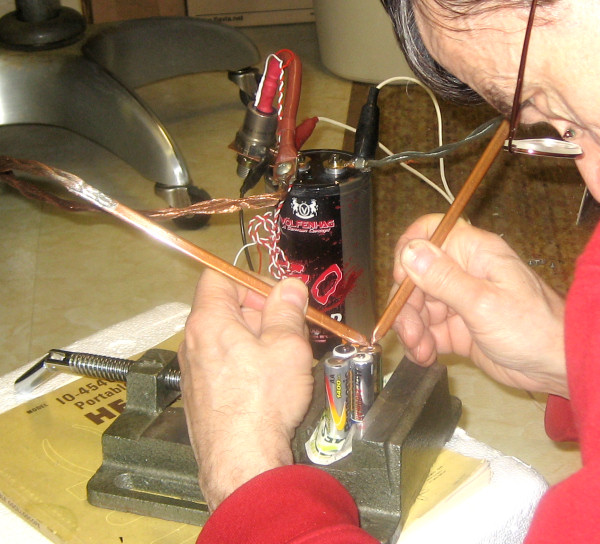
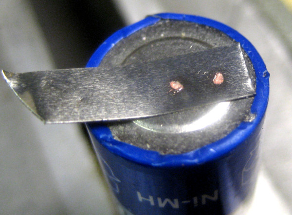
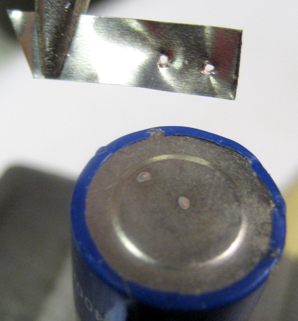
Grommets

Grommets
I found some real brass grommets to dress and reinforce the holes for the hangers. I bought the “kit” with the setting tools. I took one of the sides with the “tube” that goes through the material and used a fine round file inside to sharpen the edge, hoping to use it to cut through the sign materials. With some effort and sore fingers, I could twist it back and forth a lot and get through the paper (tested on the scrap, of course) and even through the plastic. Unfortunately, the aluminum was too hard. But the sharp edge did make a nice mark on the aluminum, so I could see right where to cut the holes with an Xacto knife. Not too hard. The second one went better than the first 🙂 After I had good holes, setting the grommets went quite easily.
Finish overcoat
I had decided to use a fast-drying exterior polyurethane, but didn’t have any (only interior) and surprisingly didn’t get much encouragement that it was available by looking online, and it was getting late. So I went back to the original plan of using UV-resistant Krylon acrylic spray, though it only said “moisture resistant”. 🙁 I did 4 or 5 coats on each side. Since I didn’t want it to run, I planned to spray with the target side of the sign horizontal.

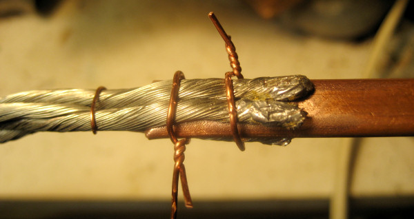
Wire feet
To do both sides in fairly quick succession and allow a fan to dry both sides, I made some “feet” out of baling wire and stuck the ends into the open flutes in the corrugated plastic. I’d spray one side, let it dry a few minutes, put the feet in so that side was down but suspended maybe 2″ above the newspapers on the floor, and spray the other side.

Spraying final coats
I don’t know whether my technique was just wrong or what, but it never got uniformly wet enough for running to be a problem at all. The final surface was quite rough. I may have sprayed so lightly that all I got were independent dry droplets. But it felt like I was applying enough. Yet another mystery.
The only surprise with the spray coating was that it raised the edges of the panels on the back side (the flimsier “Adventure paper”, stuck down with the weaker Elmer’s adhesive) in a few places. There was also a bubble I hadn’t noticed before after a few coats.
I did run the front side under a stream of water in the sink after the final coat dried, and the water beaded up as nicely as you could ask for. I guess there’s hope!

Front - final

Back - final

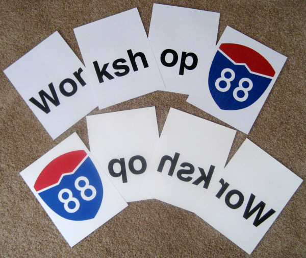
 Our second project was basically successful – and it’s done! That’s it on the right. Close friend and nutcase enthusiastic grandmother Nancy had a great sweatshirt with several variants of “grandmother” embroidered on it – but it didn’t include her preferred name: Nonnie. The layout conveniently had a suitable space for adding one more name – so we took advantage of it. I started by taking a picture of the original shirt. We sewed out a version of “Nonnie” using a font built into the machine, took a picture of that, and through the magic of digital editing created some pictures she could look at.
  She liked the font, so we brought the sewout to her for a closer look. She picked a color and we thought we were all set.
 downloaded it, loaded the letters into an embroidery editing program, and made a single design of the sequence of letters at the correct size. That’s what we ended up using on the shirt. We succeeded fully in having the strokes not look scrawny, and in fact overdid it. But having the most bold word on the shirt be hers isn’t a bad thing.