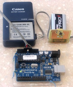
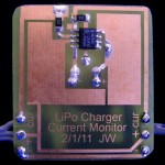
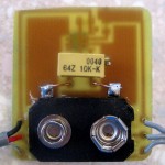
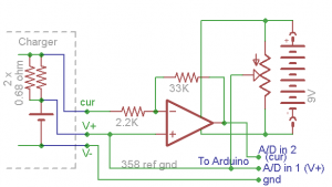
 I had another board I needed to make, so I laid out a quickie for an LM358 based amp to let me measure current while charging Canon camera batteries with the connections I’d hacked into the charger a while ago. I took a chance and didn’t prototype it: I hoped I could design something with one opamp and a couple of resistors without screwing it up.
Only test so far is that I could set the ref gnd pot to null out the offset input so I get 0V between outputs to A/D channels 1 and 2 with the current sense input shorted to the “V+” input. This is obviously battery voltage dependent,
 but it won’t need to be done very many times.
The circuit is kind of strange, but I think it will work. The negative side of the camera battery goes straight thru to Arduino ground. Battery + goes straight thru to one A/D channel so the Arduino can measure battery voltage. Should never be > 4.2V or so, so the 5V range of Arduino input should be good. That battery + is also connected to “ground” of the current sense amp.  The current sense voltage is a small increment above V+, and gets amplified ~15 times and inverted by the opamp and is applied to the second A/D channel. The Arduino can measure that voltage (and thus compute the current) as a difference from the voltage it sees on the V+ channel.
Next step is to verify operation of the sense amp and calibrate the it. I’ll apply say +0.2V on the current sense input with respect to “V+” in and verify I get about -3.0V on the A/D 2 pin with respect to A/D 1. Assuming that works, I’ll adjust the calibration constant in the Arduino code (which doesn’t exist yet). Let’s see – 0.2V across the 0.34 ohm current sense resistors is 0.588A. So I tweak the current calib constant for indication of ~0.588A.
I guess the code will look something like this:
- init A/D ports 0,1 for input with 5V range
- #define VoltCalib  5/1024 # 1024 counts in 10 bit A/D channel
- #define CurrCalib 0.588*VoltCalib/3  # guess: 3V -> .588A
Main Loop:
read A/D chan 0
BattVolt=AD0*VoltCalib
print battery voltage
read A/D chan 1
Current=(AD0 - AD1)*CurrCalib
print current
I have more pressing projects right now (like rebuilding a recording preamp/limiter so it’s ready to go for a square dance weekend in a couple of weeks), but this one will come up again…
UPDATE A FEW MINUTES LATER ON LOOKING AT THE BOARD LAYOUT:
Damn – assumption about being able to design something this simple without screwing up was wrong. I put the battery clip on backwards. Fixing that is pretty simple – swap the leads. But reversing the supply voltage to the opamp probably blew it out. I thought everything was ready to go when I got some time to do the next steps. Rats.
UPDATE AGAIN AN HOUR LATER…
I swapped the 9V leads and then couldn’t help myself – I checked out the amp. Sure enough, it was completely dead. I cut the old chip off and put a new one in. At least I got a little more practice with surface mount repair 😕 The good news is that it does in fact amplify – and about 15X, as designed. The bad news is that in addition to the implementation screw-up of reversed battery leads, I must have been on drugs when I thought moving the center point of the supply would let me null out the offset voltage. Specs on a 358 showed input offset voltage of up to a couple of mV. That’s what I was trying to null out. Hmm – the back of the envelope says with gain of 15 that would be an error of ~0.05V. With the calibration that 3V ->0.59A, it gives (0.05/3)*0.59, or about 10mA. I guess that’s not as bad as I thought. And that offset should be fairly constant, so worst case I could correct for it with an additive term in the code. OK, that’s not so bad, though I really didn’t have an extra hour to spend on this project.


Book marked, I really like your blog! 🙂