I’m well into the prototype stage of 2-channel IrDA IR comms Arduino shield for the Workshop 88 Educubes GGHC project.
Very efficiently, IrDA uses very short (~10μs) IR pulses, which must be delivered by the UART driving the IR transmitter. This really requires a special pulse generator on the send side, and a pulse stretcher on the receive side – a special hardware driver.
The first chip I found with IrDA drivers, the MCP2120, took TTL levels in and did the pulse shaping to talk to an IrDA transceiver like the Vishay TFDU4101s we have. Unfortunately, the ATMega 328 only has one UART, and usually uses it to talk to the console in its IDE. It does, however support I²C and SPI, so I next looked for a dual UART chip I could talk to with I²C/SPI and had built-in IrDA drivers. I settled on the NXP SC16IS752.
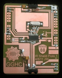
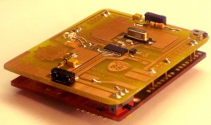
We were obviously going to need a board to host the UART and the IR transceivers. Since the main brain of the Educube is a Diavolino (Arduino clone), a shield was appropriate. Since the LCD display is hosted on another shield, there were shield-stacking considerations, too. Fortunately, the crystals I’d already bought for the unused MCP2120s would also work with the ‘752.
After a round of stupidity about which side the foil was on for the shield pins to line up, I had a board layout with the ‘752, its crystal and caps, Arduino shield pins, an LED on one of the ‘752’s GPIO lines for ‘hello world’ or whatever, the IR transceivers, easily replaceable transmit current limiting resistors and a local cap for nice sharp rising edges on the IR pulses, a button on one of the unused Arduino pins (D10) possibly for a ‘debug’ mode, pads for receptacles for the pins on the battery packs we had, a diode in series with the battery (since the 4×1.6V from new cells is easily beyond the absolute max voltage of 5.5V on some of the chips), an on-off switch, and a layout for a 3.3V low-dropout regulator (which is ordered but not in).
Since I was working on a part that is in the critical path for a project with a short deadline, it seemed like a good time to try out a new PCB etching technology I had never used and was completely unfamiliar with (rather than my always-works ammonium persulfate). But I read about the cupric chloride etchant someplace on the Internet, so it must work 🙂 I don’t know why they never laugh when I say things like that at work.
The board came out just about perfect, and the new etchant is a pretty green. I don’t know if it has enough Cu++ in it yet to work next time I use it, when the H2O2 initial oxidizer is gone. That’s for another time.
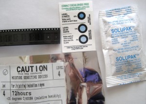
I didn’t have much trouble soldering the fine-pitch 28-pin chip (bless you, solder wick!), and the rest of the board was very straight forward. Since I didn’t have the stackable headers yet, I just soldered the shield to a few pins on the still-headerless Diavolino. I needed 7 pins and added 2 more for more mechanical strength. The extras were overkill – it’s mechanically very solid. An interesting part was the dire warnings
on the outside of the package about the IR transceivers being moisture sensitive. Huh? But a read of the Jedec standard explained it. Who knew? I was very careful to seal the package up as soon as I’d removed the two transceivers I needed.
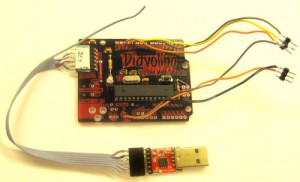
After I figured out the ATMega on the Diavolino didn’t have a bootloader, I followed a cookbook page and used my Duemilanove as an ISP to burn a bootloader into the Diavolino. Worked fine. The picture below still has the connections I used to burn it.
The one missing piece was 3.3V for the UART. Fortunately, I’d bought a couple of $6 USB-TTL adapters (from China via Ebay) which used a CP2102 rather than the standard FTDI chip. (And cheaper than the $15 FTDI cables!) But it’s just a serial port, so I figured it would work. The adapter has a 6-pin 0.1″ male header, with a different pinout than the standard FTDI cables (and the header on non-USB Arduinos, like our Diavolinos). I made up a dual female cable that got the right signals to the right places. The bad part was that they didn’t bring DTR out on the cheapie adapter. I think the Arduino IDE bounces DTR to reset the processor before (and after?) a download, so I have to watch and push the Diavolino’s reset button after the compile is complete each time I download code to it. (The 2102 does have DTR, and a hack with some very fine soldering to bring it out may be possible.) But the good news is that the CP2102 has a 3.3V regulator on the chip – and it’s brought out to the header! So I left one flying lead from the cable carrying 3.3V and soldered it on to where the missing 3.3V regulator on the shield would go.
OK – board is populated, I can talk to the Diavolino, and I have 3.3V. How do I talk to it?
A Google search for things like “arduino sc16si752” got 2 hits. One was a woman who was searching, precisely as I was, for an Arduino library for this chip. (It claims to be register-compatible with the good old 16C450 UART, so that was what we were actually looking for.) She didn’t find anything. The other was from Sarah Nordstrom, apparently a founder of StrichLabs, which is about to produce a MultiSerial Arduino shield – using a ‘752! She pointed me at her github repo with code for her almost-complete board. I was in luck!
So after studying some I²C tutorials so I could figure out how she would be talking to the chip, and studying the ‘752 datasheet and the 40+ registers it contains (and which ones must contain what magic bit patterns to allow writing to other registers – like the Modem Control Register, which contains the bit to enable the IrDA driver) so I could figure out what registers she was talking to and why, and studying her code so I’d know what objects and methods were available, I started with one of her test programs and hacked it down to a ‘hello world’ to blink the LED on the GPIO pin.
It worked! (Well, after I fixed a couple of basic syntax errors so her lib would compile (!?), and made public the private register read/write methods so I could talk to registers, along with a couple more stumbles.) The I²C connection was up, my stolen 3.3V worked, I had the right chip address, and I could write to a couple of registers!
Could I talk to the IrDA transceivers? I added a one-byte serial write to my LED blink loop and looked at the transceivers with a digital camera. Blinking! Can’t tell if it’s intelligible, but the UART is putting something out when told to, and the transceivers are working well enough to light their LEDs!
But the two transceivers behave differently. When sent two bytes 200ms apart, one channel blinks as expected. But the other blinks a lot more randomly. There is one difference in the board: the transceiver has separate Vcc inputs for the electronics and current for the LED. The datasheet suggests a series resistor to current-limit the LED, at least for short range and for power saving. I’d put large pads for those resistors on the foil side of the shield – which faces away from the Diavolino, so it’s accessible. I didn’t know what values to use, so I put 100Ω on one transceiver and 330 on the other. The one with the 330Ω blinked more sensibly. Maybe the 100Ω was too small and the chip was doing some protective thing. I tried a 470 and the blinks looked a little different, but still not right. Hmm.
How about receiving? I added a while loop for received chars on each channel, printing whatever it got. I tried holding a mirror up to the transceivers, hoping to hear their “L” and “R” data bytes coming back. Nothing. But the ‘good blinking’ channel reliably reported receiving an “R” for each blink – even with no mirror. The IR transceiver data sheet says something about the receiver working in ‘echo mode’ while transmitting. I wonder if that’s what’s happening. Also – I think it’s half duplex at best, so a transceiver can’t listen to its own IR. Maybe I can set up three mirrors and have them hear each other. Ugh.
Lots of debug prints later… The chip has duplicates of the first 10 or so registers – one for each channel. Part of the I²C protocol is a sub-address mechanism which the ‘752 uses to specify which channel is being addressed with those duplicate registers. I tried to read back values from some of the registers, but despite identical channel initializations, got different values for the 2 channels. Only the second channel I initted (using MultiSerial::begin()) had the right values. Some digging later, I found that the lib used a UART reset flag to ensure it was starting from a known condition. That’s fine, but unfortunately there’s only one of those – not one per UART – so the second init would unset whatever we’d set with the first begin(). This is a real bug in the library. I put a static state flag in so it would only do the reset the first time begin() was called.
After that worked, I told each side to ignore its own transmissions (easy, because one side only transmitted ‘R’, the other only ‘L’) and print anything else it heard. Then I arranged three mirrors so each transceiver should see the other – and they saw each other’s transmissions!
OK, but that won’t work well in the real world. I need to flush received data very immediately after sending. There is a flush() method, and it seems to work. My main loop is now:
read & print R chan
send R chan
flush R recv
delay 2 ms
read & print L chan
send L chan
flush L chan
delay 2 ms
goto top
I think I’m now confident enough that the board works that I can make another!
I really also need to pack up the hacks and fixes to Sarah’s lib and send them to her. That’s what open source is all about.


