As part of upgrading the W88 infrastructure, we’d like better records of who’s in the space and when. The new lock on the W88 front door only allows 2 combinations, and so isn’t very helpful in logging who’s there.
This project hopes to fix that by reverse engineering the connection between the keypad on the outside and the lock mechanism on the inside, intercepting keypresses from the outside, comparing them to a larger list of valid combinations, and if a valid one is entered logging that code and spoofing a valid code into the lock to open the door. Bill and I have made some initial progress.
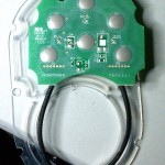 The keypad has 6 buttons and is backlit with 3 red/green LEDs. While there are spots on the keypad PCB for other stuff, nothing else is populated on our board.
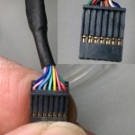 The connection between the pad and the lock is a 14 conductor cable terminated as two 7 conductor pads on the keypad and a 2×7 female header apparently on 0.05″ centers.
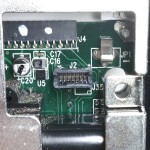 Before we took it apart far enough to see the keypad PCB, we figured that with that many wires, each button was probably brought out as 2 contacts. Using an audible continuity tester in the good multimeter, we guessed what the connector layout might be and tried to find which contacts went to which button. Nada. We had some thin wire that fit nicely into the connector and even took 6 pieces of wire, picked 6 random holes and tried to increase our chances of finding at least something by connecting the continuity checker to them 3 at a time. After a couple more tries that way, still nothing. Concerned that it might use the conductive carbon contact technology in some cheap keypads and the resistance was too high to trigger the audible indicator, we even started looking at the ohmmeter indication rather than listening for the noise – still nothing.
After taking it apart enough to inspect the PCB, we visually traced the 2 connections to each switch and then had no trouble hearing the switch closures. We were just unusually unlucky in the pin choices we blindly made initially.
The good news is that both sides of each switch are in fact brought out to the connector, so sensing which keys are pressed and spoofing presses to the lock shouldn’t be too hard.
Here’s the pinout of the connector, looking into the holes, with the key shown:
 The pin numbers are numbered pads on the keypad PCB and match the numbers marked on the lock PCB male connector. Keypad switch and LED pin numbers are shown.
No info at all on the single-row female header on the board that’s visible through the battery compartment except that it’s more like 0.08″ centers than 0.1″.
Update 6/10/11: OK, the 2×7 header from the keypad is “1.27mm”; the other as yet unexplored female is 2mm. I’ve ordered M and F 1.27mm, and some M 2mm from Digikey. <grumble>Shipping was as much as the purchase. </grumble> Started to make a little 6 push button array for dev/test. Got a chunk of the key detect and main loop designed, at least in my head, during the 6 hours drive to St Louis for the square dance weekend.
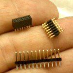 Update 6/14/11: The connectors arrived, but I’m not going to have time to touch it until next week (since we’re going away to another square dance weekend and I’m working desperately on some recording electronics for it). I did start writing some code over the past weekend before the design thoughts I had in the car evaporated. (Sorry for the blurry picture. My good camera is off taking pictures of the driveway.)
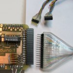
Update 6/20/11: Made a (first version of a?) shield to provide a place to terminate the 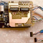 cables to the lock and host the 2 reed relays I hope to use to spoof keypresses to the lock. (This was the first board I’ve used cupric chloride etchant for. Worked OK, a little slow.) From the pinout above, I needed eight pins to the keypad (1-5, 6, 7, 8 ) and six to the lock (1, 4, 5, 6, 7, 8 ). To keep the keypad LEDs working, 6, 7 and 8 must be connected straight thru, and to simplify the board layout while connecting those, the Pin 1 of each cable is at the far end of the termination pads; the two Pin 8s are adjacent in the center. All the keypad switches are covered by pins 1-5. If I use a minimalist code to the lock – like 1 1 1 1 – I need 2 relays to spoof the “1” and “unlock” keypresses, and of course diodes across the relay coils to protect the Arduino output drivers. I might have gotten away with MOSFETs or possibly normal transistors, but relays always work.
I avoided Arduino pins 9-13, as at least some Ethernet shields use those. I put pads in for several other lines, most notably Tx+Rx, with an eye toward easy hacking if other functionality is needed. While an Ethernet connection would be cool, it looks like all we’d really get is ascii strings, which could be handled just as well with a serial connection. If I have to do that, I’d probably opt for RS485, using the same ADM483 TTL-RS485 chip the nodes in my home automation system use. I’d use PoE or put power on the unused pins of the CAT5 carrying the RS485 signals to power the Doorduino.
During the meeting at the space Monday night I managed to solder up quickie cables to the 1.27mm headers that intercept the keypad connections . (They’re ugly – those pins are really close together!) But somebody brought a Makerbot and that was too interesting to ignore, so I didn’t even get to plug the cables into the lock.
A very incomplete bit of code exists, so maybe by the next time I can get in there will be something that might work.
Update 6/22/11: Most of the skeleton of the code is in place. Still just stubs for reading from some computer to update the member code database and for reading the database from EEPROM, with 2 member codes hard coded in to test with.
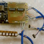 I also tacked a little set of buttons on, hopefully wired just like the buttons on the keypad. Approach for reading a key is to set one pin to output and write high to it, then read the other pin. If it sees 1 the key is pressed, else not. It sorta works, but I get way too many false positives – reading 1 when the key isn’t pressed. I should have put pulldowns on all the lines – oops. That’s the next hardware step. Then I should be able to use the buttons to debug/test the keypress/member matching logic.
Update 6/24/11: Pulldowns: Russ said floating Arduino inputs were _really_ noisy, and were especially affected by the state of the adjacent pins, so I did a quick test to see what pulldown value I’d need to get reliable reads of the keys. Using the TestKey(key) function already in the code, I chose the 7/8 key, whose sense pin (5 from the table above, which maps to A1 on the board) had both physical neighbors (A0, A2) free. I set A0 and A2 to be outputs, and did trial runs with those 2 pins in each of the 4 possible states. To return true, the debounce logic in TestKey() must read the pin as high 3 times in succession, with 20 mS delay between.
In 1000 trial runs (4000 calls to TestKey()) with no pulldown, it got about 2600 false ‘true’ indications. In every case with both neighbors set high, it gave a false true. For other cases it read some 0s correctly. In 1000 trials with a 470K pulldown to ground, it read zero false trues. A 1M pulldown seemed to do little or nothing. All test runs were with the key not pressed; it always correctly reported true when the key was pressed.
Due to the unusual wiring of the keypad, where some pins must be set high to read one key while being the sense pin for other keys, the cost of the pulldown is that when I need to force a pin high, the pin’s output structure must source enough current to overcome the pulldown. At 470K, that’s 10 μA – trivial for the Arduino pins.
I now feel free to use whatever value pulldowns – say 100K or less – I can find 5 similar 1/8W resistors for in my junk box. The Doorduino shield will look a little uglier more interesting showing its history with the resistors tacked on, but function wins over form.
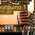 Later: OK, I put the pulldowns in. Big and ugly, but they work, and the buttons seem to work pretty reliably. Or at least the little test buttons work. It’s never been connected to the actual keypad yet.
I did manage to screw up the wiring, though. The pulldowns were supposed to go to ground – which is available right there about 0.3″ to the left of where the left sides of the resistors are connected. I wrong-headedly fitted the resistors to go into the pad by A0 instead of ground pad. Fortunately, I wasn’t using A0, so I set it as output and wrote a LOW to it. Works, but it was dumb.
A little worse is that I think I didn’t need them at all! The approach to test a switch was to set the pin connected to one side as output and write HIGH to it, then sense the other end with an input line. Of course I needed the pulldown to make sure it was low if the switch wasn’t pressed. But I think I could just invert the logic, write a LOW to the output pin, look for a 0 to say the key was pressed, and use the internal pullups on the input pins to ensure the input was in the high state when the switch wasn’t pressed. (The analog pins do in fact have pullups just like the other pins.) I haven’t decided whether it’s worth tearing the dumb resistors off or not. But I hope next time I’ll think to do it that way.
Button detect logic seems to work, and I can reliably enter any of the three code sequences I’ve hard coded in and have it identify which sequence it is and call unlock(). Changed the #define for length of keycode from 4 to 5 and it worked exactly as expected (after I increased the database contents to 5 keys each).
Update 6/27/11: Went in to the space Sunday for cleanup day and had a little time before the others arrived, so I played with the lock. The connectors do fit, but it will be interesting to find a way to get the cables into the lock. The user interface from the keypad is not what I thought: It unlocks as soon as the last key in the code sequence is pressed. I thought you had to press the “Lock/Unlock” button as a sort of “enter” key, but that’s not right. It’s a “Lock” button only, and will always lock the door. I modified my code to a) not expect a Lock keypress at the end; b) to not send a Lock keypress as part of the spoofed sequence I send the lock to unlock it; and c) respond to a Lock keypress by spoofing a Lock keypress to the lock. I couldn’t actually try it because I didn’t have a laptop to update the code and power the Arduino while plugged into the lock.
Russ got an Ethernet shield, and it seems to use the pins I left available for it. It also has female connectors on the top so I should be able to plug my shield into it.
Likely access (without cutting holes in the metal frame of the lock) is down an empty space near the battery. Unfortunately, there’s barely room for one cable, let alone 2. Decisions to be made and work to be done! Short term next steps are:
- actually test lock/unlock commands to the lock
- actually test keypad input to the Arduino
- figure out how to modify the lock case to get cables into it and still connect the battery
- modify the case, mount Arduino, etc
Mid term steps:
- define protocol for database updates from computer
- define protocol for lock activity log messages to computer
- get (Russ to get) Ethernet connectivity working to implement above
Update 7/12/11: Got to the space and made some progress today. Main goals:
- verify that it could talk to the lock and to the keypad
- try to see if that single-row header could be useful
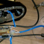 I took the electronic/motor part of the lock off the inside of the door so I could work on it from the comfort of the table, and using the very crude cables I’d made out of Cat5 (almost completely inappropriate for the task) I plugged the Doorduino into the lock. After some repairs to the clunky cable, I succeeded in sending both lock and unlock commands to the lock, both triggered by appropriate key press sequences on the surrogate keypad I’d hooked on.
While the lock command worked just as designed, the unlock command just produced lots of beeps from the lock. I soon realized I hadn’t reprogrammed the lock to accept “1 – 1 – 1 – 1” as a valid unlock code. Once I did that it unlocked fine.
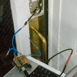 Then I brought the Doorduino and the laptop over by the door and plugged it into the actual exterior keypad. Sure enough, it recognized presses from the keypad, and when I entered the user code sequences I’d hard coded in, it identified which user it was and called the unlock function. Great!
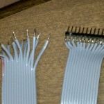 To facilitate testing the mystery header, I made a little breakout cable. With power applied, I looked at the voltage on all the pins (with respect to the negative side of the battery). Found some +6V, some +3.3, some ~0V. Nothing surprising. Since there were 14 pins – same as the connector to the keypad – with the battery out I tested for continuity from both end pins on the header to the 4 corner pins on the keypad connector. Nothing. It’s clearly not just alternate access to the keypad connector.
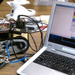 Finally, I connected a logic analyzer to the breakout (sorry for the cluttered picture) using battery minus as ground and caused the Doorduino to issue lock and unlock commands. Since the analyzer only has 8 input pins, it took two runs to watch all 14 header pins. While it showed a collection of hi and low levels on various pins, there were no transitions at all during lock and unlock events. So much for the vague hopes that it might provide access to the lock motor pins.
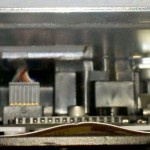 I have figured out a little more about the lock from playing with it multiple times. Looking down into the hole on top that the battery pack slides into, in this photo from Andrew you can see two white plastic guides that about line up with the mystery header. I suspect strongly a programming or diagnostic card with a male header slides down into those slots. Looking at the instruction card visible when you slide the cover off, in addition to a DIP switch and the “program” button, there are 2 small round white buttonish things near the top that don’t seem to do anything at all. Having had them in my hand, they’re part of those white plastic guides. (You can see most of the one on the left in the picture.) I suspect strongly they provide access to a couple of tiny buttons on the programming/diagnostic card. No clue what they might do, but at least that probably explains their existence.
I also learned that if it beeps a lot and the keypad flashes red and it will unlock but not lock, it needs batteries 🙂
Now that I know that I can operate the lock motor and read keypresses from outside and that the mystery header probably won’t be very helpful, the next step is to make much better cables from thinner, stranded wire, with strain reliefs and better insulation. And there’s still the issue of moving the battery pack to make room for the cables.
Update 7/18/11: I didn’t have any suitable wire to make new cables, so I went to Fry’s to see what I could find for thin stranded wire. Not sure, but 26-30 ga is probably what I’m looking for.
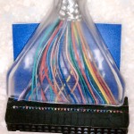 I stumbled on almost exactly what I needed in a floppy cable with the extra fine pitch ribbon cable. “Normal” ribbon is 0.05″ pitch; the stuff with an extra shield conductor between the conductors that are used is 0.025″. But most of the ribbons were one color, making it slightly more challenging to wire the cable correctly. But I ran across an 18″ non-ribbon cable with lots of colors. I’ll cut it up and it should be just what I need.
There’s been a little discussion about leaving the existing keypad functional in case the Doorduino (DD below) fails. That requires different cabling, so I need a final group decision on which way to go before I can actually make the cables. There are two basic options:
Option 1: The original design.
- The original keypad goes only to the DD allowing it to read keycodes from that keypad for checking against the internal database. The lock can no longer read the keypad directly.
- The connection to the lock is essentially just enough for the 2 relays on the DD to spoof keypresses on the Lock and 1/2 buttons. We program a code of 1-1-1-1 into the lock. To unlock, DD makes a series of contact closures on the wires to the 1/2 button to spoof pressing that key 4 (or however many) times.
- Pros: Can use existing keypad. (Doesn’t rule out adding a different keypad later if we have enough I/O to connect it to the DD.) The current wiring plan also allows existing red/green LED feedback on the original keypad. Works now.
- Cons: The existing keypad’s 5 buttons could allow for unintentional duplicate codes. For example, 1-3-5-7-9 is just the same as 2-4-6-8-0. Not a show stopper, but we need to watch for it. If DD fails, only access is with a physical key. (If we cache the database on the DD – as is planned – failure of the main computer does not affect access.)
Option 2: Leave existing keypad connected to lock.
- Make cables so the relays are in parallel with the Lock and 1/2 keypad keys. Probably not too hard.
- User entry is from another keypad.
- Pros: Original keypad works if DD fails. Separate full keypad avoids duplicate codes.
- Cons: Keycode 1-1-1-1 would work from the outside. This is bad. Need new outdoor keypad and to interface it to DD. Not sure how LED feedback would work.
Update 7/22/11: Based on the feedback I received, I’m going to proceed with the original plan 🙂
I cut up the floppy cable and found the wire to be about perfect. Soldering to the tiny pins of the connectors to mate with the lock/keypad cables was a challenge, but I think I did a pretty good job. Here’s the color code. It’s the same for both cables.
| 1 | blue |
| 2 | red |
| 3 | yellow |
| 4 | green |
| 5 | purple |
| 6 | gray |
| 7 | tan |
| 8 | pink |
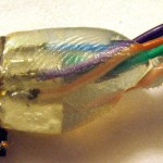
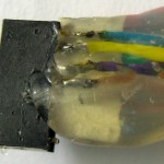
I put paper between the rows of pins and encased the pins and a little of the wire in hot-melt glue as a strain relief and insulator. While I believe firmly in the better reliability of pigtails – avoiding an extra connector pair – I also replaced the original soldered-on pigtail approach with a 0.1″ header. I figured if I needed to remove the DD (like to program new user codes until the network stuff was in place) I didn’t want to have to take the lock apart to get to the connectors. After I’d put the female header on I realized I could just unplug the shield from the Arduino (now a Diavolino). Oops, too late.
I used a hot-melt strain relief on the 0.1″ male end of the cable as well. It turned out that a soft clear plastic fan shaped cover from the floppy cable fit almost perfectly over the header, so I used that, too.
It’s pretty much ready to go for testing. I hope I kept the wires straight, but the test is the test. And with the much thinner wires, there’s a vague hope that I can squeeze them in without extending the battery holder! We’ll see.
I’m seriously considering removing the dumb pull-downs, since they’re both ugly and unnecessary.
Update 7/23/11: Well, I thought it was ready for testing. On looking a little closer, I realized I made a mistake and also made a decision (bad, in hindsight) that could have, but didn’t save my butt. I need 8 (of the 14) pins to go to the keypad to get all the switches and the LEDs, but only 6 to go to the lock (since the DD only has relays to spoof 2 of the switches). Murphy won, and I put the 6 on the female instead of the male.
A little worse, I thought about running all 8 wires to both connectors, since the pinouts were identical (obviously, since they interpose between 2 connectors that plug into each other). I already had all 16 terminated at the DD end. That way if something weird and unexpected happened – like DD was redone to spoof all the switches – all the wires would be there and connected. But the chances of needing to spoof all the switches (adding 4 more relays to the DD shield) were pretty slim, so I took the short cut of not soldering in the other 2 wires, saving maybe 2 minutes. (I did just fold them back into a bit of heat shrink, rather than cutting them off. I guess I learned something from past flubs.)
Of course the unexpected thing didn’t have to do with the relays – just with being dumb and picking the wrong connector to shortchange. Switching the 2 connectors’ functions – keypad/lock – at the DD end is trivial: the 16 pin header is symmetrical, so flipping it over would swap the 2 cables. If I’d only connected all 8 wires on both connectors, I’d be all set. But I didn’t.
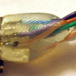
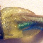 You can see the bit of card stock I put between the rows as insulation, and the fingerprints where I formed the hot-melt while it was still hot. (Wetting your fingers works great!) You can see the 2 unconnected pins – 2 and 3, referring to the diagram earlier. I also cut off the unused 6 pins, since I don’t even know what they do. Looking at it closely, it looks like a pretty effective insulator and strain relief. Fortunately, pretty wasn’t in the requirements 🙂
OK – now how to fix it? I do have a spare connector (ordering 2 was cheap insurance), so I could just cut the wires off and start again. And I think I have enough wire that it would still fit. Of course all the connections are now potted in hot-melt, and I tried extra hard to work the stuff in to really surround the pins. So reusing the existing connector would require removing the hot-melt – non-destructively. I guess I’ll try using the hot air station and see what happens. But I sure am glad to have that spare connector as Plan B!
Much later…
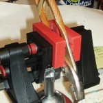
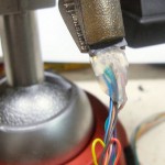 Interesting process. I chose to try to surgically remove the glue just from around the pins that needed their wires. I used rubber bands and a pair of pliers to hold the connector, and a desk vise to hold the pliers. That let me get a pretty good angle for the hot air gun and the toothpick I used to scrape out the remelted glue. Here’s a little clip: RemovingHotMelt.
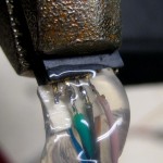
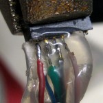 The hot air station remelted the glue just fine. I could pick out the glue from around the pin of interest pretty well. I finished cleaning up each pin by scraping it (cold) with an Xacto knife. I tinned each pin after I removed the glue, and it tinned fine. A little careful soldering, and I had the connection I needed. After soldering both wires in, I added some more hot-melt to remake the insulator/strain relief.
An interesting effect of using the hot air on the glue is that as it melts from the outside in, it effectively removes the ugly cloudiness from fingerprints introduced as I shaped the still-hot glue with wet finger tips. It’s still bad, but with the glue more clear, it’s a little less ugly. I’ll have to remember that trick the next time I make a hot-melt strain relief!
Each wire tested OK with a continuity tester, so I think I’m back to where I thought I was yesterday: It’s ready to test out on the lock.
Update 7/26/11: Major progress this evening after the LED scrolling display hacking session. First, the new, thin wires fit past the unmodified original battery pack. That simplifies things a lot. Then I tried each connector (to keypad and to lock), and each worked by itself, so I tried the whole thing end-to-end. First I had to stuff the connectors behind the lock and get it to fit back on the door. After a couple of false starts, I got it all to fit. Test time: And it works! I could use the keypad outside to punch in the user codes I’d hard coded in and the door unlocked and locked and logged user access just as it should.
Now for a touchier consideration: It was a (small) hassle to get the new connectors stuffed inside the lock, but if I unplugged the DD, the lock wouldn’t work. And the Doorduino had no mounting or source of power, so I couldn’t leave it in place. 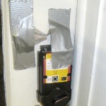 Fortunately, I now had all 8 pins brought out from both the keypad and lock connectors. I dug around in my parts box and found a long enough female header to cut a 16 position header that would mate with the connector to goes to the DD. Eight bits of wire and some soldering later, I had a jumper cap that looped back the connectors, pin for pin, and the lock worked again. I taped the connector (with loopback cap) to the door and called it done for the night. If you can’t leave wires duct-taped to the front door in a hackerspace, where can you?
Next software steps are putting the user database in EEPROM, isolating the initial user code definitions to a nicely structured separate header file until there’s network connectivity, and starting the network stuff. Next hardware steps are arranging for power over the network cable (it won’t be proper PoE, since that requires extra hardware on the network shield) some kind of mounting, and probably at least a minimal enclosure. I’d be delighted if someone else built a beautiful enclosure for it, but I’d like something to keep it from catching on people’s clothes, etc. I may take off those ugly pulldown resistor too.
Many thanks to Andrew and new visitor Dan Gray for sticking around to help!
Getting close!
Update 7/30/11: Tested out DD duct-taped to the door with a battery pack on Makerbot build day Friday 29th. We went to lunch and it locked the door when we left and unlocked it for us when we came back!
As an interim arrangement, it currently gets user codes and names from a clean, separate header file as PROGMEM, puts them into EEPROM, then uses the data from EEPROM for keycode validation as it will in the final version. It doesn’t deal gracefully with the number of entries yet – that will probably end up as the first byte in EEPROM. The header file entries are pretty easy to manage, and look about like this:
userCode userCodes[] = {
    "Bob",{0,1,2,3,4},
    "Ted",{0,2,1,3,2},
    "Carol",{4,3,2,1,0},
    "Alice",{0,1,2,1,0}};
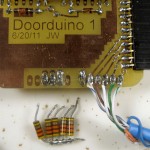 I’m off to a square dance week and since the Arduino dev environment isn’t physically very big, I’m bringing the DD with me to finalize the software a little more. I hope to fix up the EEPROM stuff and get it to at least acknowledge the Ethernet shield. I’m confident enough that I can get it to work without the dumb, ugly pulldown resistors that I pulled them off the board. Did my heart good, but that logic now also needs to be fixed before DD will work again. I may be able to make at least some design headway on figuring out how to get power over the Ethernet cable (but not PoE).
Update 8/8/11: Got keyboard sense working with pullups (no more pulldowns!), cleaned up EEPROM stuff some so the database (user codes and names) is in a header file that is conditionally compiled. If present, the data from the header file is written to EEPROM; else there better already be something in EEPROM! In any case, user code validation and name lookup for logging is always from EEPROM.
I tried to get the Ethernet shield working with some example code. Some LEDs on the shield blinked, and it indicated link, but didn’t work at all. Wouldn’t even respond to ARP requests. Is the shield bad?
 I was using it with a Diavolino, so I tried it with a real Duemilanove. It worked fine! The shield uses SPI via D11-D13. For reasons known only to the developers, it picks up those signals (MISO, MOSI, SCK) not from actual pins D11-13, but from a non-standard socket that plugs into the ICSP header. The ICSP pins and D11-13 are connected on an Arduino.
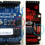 For reasons known only to a different set of developers, the Diavolino has chosen to move the ICSP header over about 1 cm from where it is on a “real” Arduino, so the socket under the Ethernet shield doesn’t have a prayer of connecting to it.
How to work around this? I could take the expensive way out and use a real Arduino. I might be able to drill holes in the Diavolino, glue pins in, and run little jumpers to connect them. Ugh. Or I could hack the dumb Ethernet shield to get those signals from the normal pins instead of the ICSP header.
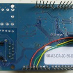 Since (IMHO) it’s the dumb shield’s fault, I just hacked that board. Three wires, and now it works with any Arduino or Diavolino.
Now it just needs power. The RJ45 jack on the shield has 10 pins – not the 8 one would expect. (That’s not counting a couple extra for the link and activity LEDs and the shield.) And a continuity tester shows both wires in a pair (say ora/whi) are shorted together when a cable is plugged in, and the two come out on only one of the 10 pins!
(Time passes; Google informs.)
OK, it looks like this is a Mag Jack – one with the “magnetics” (transformers) built into the jack. There are 6 heavy pads next to the jack, one connected to each of the 4 pairs in a CAT 5 cable (two apparently unused). (You can see them in the pic above, with heavy traces running to 2 of them. Two similar heavy traces are on the other side of the board.) They’re presumably the center taps of transformers on each pair. I don’t want to mess with real PoE, but I’m guessing (yes, it’s really a guess at the moment) that I can put say 12VDC on the unused pairs (both wires in one pair +, both in the other -) and get it out on those heavy pads – and without touching the pairs that carry the data. I was surprised that after lots of looking at schematics and details of the Ethernet shield (of which there are many versions) I couldn’t find that info and had to reverse engineer it.
There’s what looks like a nice heat-sinked regulator on the board. I wondered if it was used by PoE and if I could hijack it. But I think it’s just a 5V-3.3V regulator to run the W1500 chip. For the record, I think the PoE support on the board is implemented by a third-party add-on bit of hardware. So I think we need:
- a power injector – a 12VDC wall wart and 2 specially wired RJ45 females
- a 5 V regulator (and caps) to live on/attached to the shield, sourcing from the heavy pads, providing power to the 5V pin on the standard Arduino header
- testing!
- mounting for the DD, including some protective casing
- cabling across the door, around the frame, and off toward network and power
That would leave us with a functioning DD, less logging. User codes are still compiled in. But the network stuff wouldn’t be in the critical path for operation. If we wanted some logging, we could write to the micro SD on the Ethernet shield, but no effort has been made toward that as yet. (But I hear there is a lib to support FAT on the SD.)


