Recording preamp: new plan, better than ever!

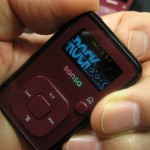
Wow – the little Sansa recorders have caused significant changes and clarifications to the plan for my square dance recorders.  I’m going to end up with almost everything I’ve asked for.  The new plan:

  • The only supported recorder will be the Sansa (Clip or Clip+), and it will be built into the device.  This simplifies issues of supporting multiple battery configurations, uses cheaper recorders and provides more storage and more features.  I never dreamed of giving up my old Iriver recorders, but I think they’re all gonna go on Ebay and get a couple of bucks back.
  • I’ll use an 850mA-hr LiPo cell (from Spark Fun).  That will run recorder and preamp for much more than a full day of recording.  Since the Sansas originally had LiPos, they also have a USB-powered charger built in.  It will take longer to charge the 850mA-hr cell than the original 290mA-hr cell, but it won’t hurt the cell and I can afford the recharge time.
  • Since the Sansa already has a battery level indicator for the correct battery chemistry, using that saves all the hassles of putting in my own.  That means no Tiny85, no CMOS switches, and no push button!  That’s a very significant simplification of the device, with no real loss of functionality.
  • The open source RockBox software gives me the valuable addition of time stamps on files, as well as very good flexibility on the start/stop trigger.  And (for changing a #define) it even lets the device start in active recording mode when turned on.  This reduces the chance for operator error and gets it a step closer to an appliance I can hand someone else to take to a weekend.  I’ve already recompiled a private version with a few tweaks to make it fit my needs even better.
  • Since there’s 2V DC on the mic input – which comes out of the Sansa – I _think_ I can use that on the gate of a low voltage MOSFET to turn power on/off for the preamp automatically based on whether the Sansa is on/off.  For a $0.60 transistor, it eliminates not only the power switch on the preamp, but also another source of operator error.  That gets the device another step closer to being appliance.  I’ll know for sure when the transistors get here in a few days.

Remaining open issues:

  • I determined earlier that I really needed 5V to get the best dynamic range out of the SSM2167s.  I need to revisit that and see if – perhaps by recalibrating the 3914 to use a smaller range – I can get away with the 3.6V from the LiPo.
  • Using a MOSFET as an automatic power switch for the preamp needs to be tested.  According to the specs it should work – but “the test is the test”.
  • The audio level in the recorded files is quite low.  At -31dB, it’s about 10dB lower than I’d like.  While I can kick it back up during post processing, I should be able to avoid that extra step if I can just get the Sansa to record the right level in the first place.  And since the recording software is open source, I should be able to make it do that.  That one’s work in progress.

Updates to follow…

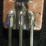
Update 11/7/11:  The MOSFETs arrived.  How to connect to a SOT-23 package to test it?  Make a breakout from a scrap of copper clad and a Dremel.  Made it, hooked it up with an LED and a resistor to draw ~20mA – much more than the preamp draws.  Turned on the Sansa and the LED lit.  It works!  That 2V is definitely enough to turn on the MOSFET.

Connection for the quick test was dead simple: Gate to the Sansa mic lead with +2V on it when the Sansa’s powered up, Source to ground and Drain to provide low-side switched power to the load.  Implementing that on the PCB will be a little more interesting, since lots of stuff goes to ground.  I guess I need to actually switch ground to the 2167 and 3914 and make sure nothing funny happens.  Pops from switching LEDs in the display impressed on the ground connection to the mic level input could be a problem.  Maybe just a big cap across D,S?

The low recording level is a little more interesting.  I found a thread on the Rockbox Flyspray bug track tool that describes exactly the problem I’m seeing.  Somebody said he’d made changes that should fix it.  But in the load I just compiled (based on late enough code that it would certainly contain his fix) the “integer overflow clipping” that forces me to use a low level in is much worse than in the stable build I first installed.  Very much work in progress.  I’ve posted my interest in helping on Flyspray and hope to start some more discussion.  I’m sure there’s more to follow.

Update 2/11/12:  Various bits of progress since the last post.  I’m just in the process of cleaning up one of the Sansa prototypes for Les.

Code

After several back-and-forths in this Flyspray task, we got a patch for RockBox that seems to fix everything.  While ultimately I should use a released build, for now, because I want to get a recorder to Les, I’m just building from a private code tree based on rb31180 with the patch at end bottom of the Flyspray task about rolled in.  The build machine is Jimsdellmini running Ubuntu 10.04.3 LTS.  All the code is in ~jim/rockbox.  The code tree for Les’ box is under rb31180, with build directories for ClipV1, ClipV2, and Clip+.

To build (takes several minutes):
– get a version (svn co -r<xxx> svn://<yyy> <local dest dir>
– cd <local dest>
– mkdir build
– find . -name “*p[yl]” -exec chmod +x {} \;  ? not tested
– cd build
– ../tools/configure
– (specify target)
– make
– make zip

Ugh – those instructions – which I got  from the Rockbox developer’s page – are no longer correct.  They’ve moved from svn to git since I last sucked down any code.  I’ll do battle with that later – I have a code tree that builds for now.

Hardware

I’m setting Les up with one of the two prototypes I used with great success at Heartland in Oct 2011  (the one with the red LED block).  I decided to cheap out and put one of the 2GB Clip (V1) devices in rather than the shiny new 4GB Clip+ that was in it.  The custom 3 pin plugs are interchangeable.  I’ve made a couple of “productization” mods for Les’ device.

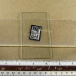
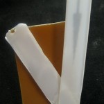
While a bare PCB doesn’t phase me at all, I made a cover out of clear clamshell packaging to cover both the PCB and the battery.  It also covers the pots for setting the LED range which really shouldn’t be touched.  Since the Tiny85 I was planning to use for a battery monitor was never used, I removed the 6 pin 0.1″ programming header.  To make it all a little more self-contained, I cut a notch so the input pigtail cable can be curled up inside, on top of the battery, for transport/storage.  (The final, smaller cases won’t have enough room to do that, so I thought I’d at least take advantage of it for his.)  I also epoxied a small block on the back of the Sansa and hot-melted it to the PCB for a fairly permanent mounting for the recorder.

—-
Damn WordPress lost my latest updates.  I’ve been keeping this open in the editor (which seems to be a very bad idea) as things are changing frequently and I put stuff in and take it back out / update it as things change.  This time(being afraid of Microsoft rebooting my machine WITHOUT MY PERMISSION) I put some last updates in and hit Update, thinking I was safe.  Wrong.  Apparently it logged me out, though it kept my editor open.  Everything I’d put in since whenever it timed me out was lost.  Damn.
—-

Rats!

I recorded with Les’ candidate (which I thought was golden) and my perfect white recorder in parallel at Chitown.  Les’ showed several places where the recording cut out, though the white recorder had music!  It almost has to be running afoul of the noise gate, but I really thought I’d set the level correctly.  Ugh – more calibration needed.  And I was hoping to have it sent to him by now.


Posted in Recording preamp/limiter | 1 Comment

What a difference 30 years makes!

While I was testing the latest version of the recording preamp, I needed a simple audio amp.  A good old LM386 would be fine.  I’ve been making stuff on printed circuit boards and vector boards for quite a while, and have been using 386s for quite a while, so  the box of old project boards seemed a like good place to look.

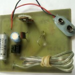
I found just what I needed – a 386 originally designed for a “light wave receiver”.  Disconnecting the photo transistor and hooking on a couple of clip leads let me finish my testing.  The amp worked fine.

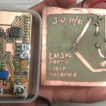
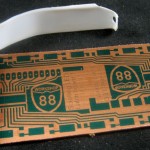
Afterward, I looked at the amp’s grungy old PCB.  As has been my custom for some time, I had put my initials and the date on the board:  10/81.  Using a low tech digital decade counter (my fingers) I realized the board was just about 30 years old!  (I guess I have been using 386s for a long time.)

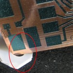
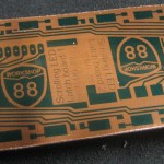
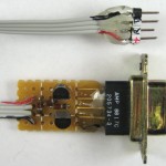
Here’s the old PCB posing with the new one it was helping to test.  Things have changed a lot since those Sharpie-as-resist-pen days!


Posted in PCB Etching, Recording preamp/limiter | 1 Comment

Rebuilding my Pogoplug house monitor server

Ya know, you’d think there would never be a situation when anybody would accidentally enter the following 2 commands in order:
# cd /
# rm -rf *
That’s what I thought, too, until I just did it today.  Below is how that happened, plus all the gory details and lessons learned of rebuilding a Pogo so it provides a friendly, working environment for the house monitor stuff (plus a little web server), and how to back up the whole thumb drive for quick repair in case disaster strikes.  The details are there in case I ever have to build it up from the ground again.

Background

Much of the history of getting my home monitor system up on a Pogoplug is described here, and it’s been up and running for months.  While we were away (at a square dance weekend), I realized I’d forgotten a critical Eagle schematic file I hoped to work on in my spare time.  There is no access to the main PC it lived on from the outside, but I could ssh into the Pogoplug 3 feet away from that PC and on the same network.  Could I hack into my own PC from the Pogo?

There was of course no Samba stuff installed on the small Archlinux distro on the Pogo.  A little googling said I needed smbclient.  I soon figured out that apt-get wasn’t the  package management tool here, and told pacman to get smbclient.  That of course was dependent on other files that needed to be upgraded, and those first needed some other upgrade.  At one point, not understanding the impact of what I was doing, I typed pacman -Syu.  That of course upgrades everything.  And on a 1GB thumb drive there isn’t room for everything, so the disk was soon full and the system almost non-functional.

But worse than that, the upgrade bumped perl up from 5.10 to 5.14.  There were apparently some API changes, and the Device::SerialPort module I depend on to talk to the RS485 network reported an undefined symbol and wouldn’t run at all.  So in addition to a full disk, the monitor stuff was completely dead.  And I didn’t even get smbclient to run to get the file I was after!

The path to stupidity

When I got home and started to rebuild the box, the first thing I found was the plugapps.com web site I’d always gotten the Linux distro from was gone.  It redirected to archlinuxarm.com (not to be confused with archlinux.com!), and I while I don’t understand what happened and who the players actually are, I did find everything I needed there.

I had 2 Pogos, each with an OS thumb drive, different hostname and address, etc.  The main one now had a completely full disk and, having failed in the middle of a major upgrade, didn’t even have all compatible parts.  It would run, but wasn’t very useful.

The second Pogo was still completely functional, and in fact was built on a 2GB drive.  The actual boxes were identical, and both had the magic bootloader in flash that allowed booting from a thumb drive.  All the following happened on the first physical box, although that’s not relevant.

I booted up from the second thumb drive, and inserted and mounted the compromised one so I could access it.  The first thing I did was pull the (one and only copy of!) the latest home automation stuff off the first drive safely to the second drive.  One gig wasn’t enough, so I plugged in a 4 gig drive to build the new system on.  I started by copying the files from the original 1 GB drive.  It would run, but since trying to finish the aborted upgrade was going to be messy, I decided to reinstall the OS from scratch, upgrading to the latest as long as I was at it.

That meant deleting all the files from the 4GB drive.  I booted from the second drive, and mounted the 4GB.  I cd‘d to the mount point and looked around to make sure it was the drive I needed to clear.  It was.  Fine.  I was already on that drive, so all I had to do was go to its root and delete everything.  So I cd‘d to /, and typed rm -rf *.

Unfortunately, while my brain was chrooted to the 4GB drive, the actual machine didn’t know about that, so my cd  went not to the root of the 4GB, but to the real root – of the boot drive with the working OS.  It wasn’t until I got a prompt back and ls wouldn’t work that I realized what I had done.  Yes, I was trying to go to the root directory and recursively delete everything.  Just not on that filesystem.  There went my one working system.  Damn.

Rebuild attempts and notes

Here’s some history of what happened next on the way to being able to make (what I hope is) a complete list (The Steps, below) of the changes I had to make to get the whole system up and working as I wanted.  I capture some details here to avoid clogging up The Steps with extra words.

I rebooted from the still partially functional 1GB drive, and mounted the  4GB.  This time I succeeded in removing the files from the 4GB drive, leaving the OS intact.

I started a basic install by following the steps from
http://archlinuxarm.org/platforms/armv5/pogoplug-v2-pinkgray:
1) Mount new drive to /usb.  Download and install Arch Linux ARM:
cd /usb
wget http://archlinuxarm.org/os/ArchLinuxARM-armv5te-latest.tar.gz
tar -xzvf ArchLinuxARM-armv5te-*.tar.gz     # This will take a long time
rm ArchLinuxARM-armv5te-*.tar.gz
sync     # Takes a while when using a flash drive

2) Clean up and reboot. Cross your fingers and hope for the best.
cd ..
umount usb
/sbin/reboot

Took maybe 40 minutes.  I removed the old thumb drive, and on reboot from the 4GB, a serial terminal showed normal looking startup.  I logged in as root/root and started setting it back up as I needed it.

For reference, uname -a gave: Linux alarm 2.6.39-ARCH #1 PREEMPT Tue Jun 14 15:55:01 MDT 2011 armv5tel Feroceon 88FR131 rev 1 (v5l) Marvell SheevaPlug Reference Board GNU/Linux

I mounted the old compromised boot thumb drive as a reference.  When I tried to go to /etc on the old drive, I ended up at the real /etc – just like when I clobbered the other thumb drive!  Rats – I was supposed to learn from that!  But at least it didn’t hurt anything.

I copied old /etc/rc.local over.  I think that should get the network up.  Rebooted, and yes – now I can ssh in!  Rats – no, I left the old thumb drive in and it booted from that instead of the 4GB.  Pulled old drive, rebooted.  No, didn’t work.  Back in thru the serial console.  No ifconfig! Or route!  Or netstat!  WTH?  Copied those binaries over from old thumb drive to /usr/bin (rather than where they came from).  What happened?

Turns out this linux distro is significantly different from the one that was running before.  In particular, “legacy” tools like ifconfig are in the net-tools package (group?), which is not included in the distro, while their iproute2 counterparts are the default tools.  Here’s a partial list:
ifconfig is replaced by ip addr (or ip a – shortened args work!)
route (like route add…) is replaced by ip route
netstat is replaced by ss (except -rn, which is ip route show)

I used pacman to install net-tools, so ifconfig and friends are available, but I guess I should start using the iproute2 tools.  (I even VPN’d in to work to see if the iproute2 tools are there on a current Red Hat 5 system.  They are – and now I wonder if some of the network scripting I’ve done in the past year or three would have been better done based on the new tools!)

Rc.conf has changed for network stuff, so copying the old file over was a bad idea.  Works fine if you just modify the file included with the distro.  Details in The Steps.

Changed sshd port in /etc/ssh/sshd_config to the standard non-public value.
Modified /etc/bash.bashrc so command line editing is vi-like and ‘dot’ is in the path.

Tried to install the little web server lighttpd, but pacman couldn’t find it.  The repos pointed to by /etc/pacman.d/mirrorlist were still on plugapps.com.  That had been redirected to archlinux.com for the main repo, but not the others.  Changing the Main Server line to Server = http://archlinuxarm.org/arm/$repo let it find lighttpd, but it recommended upgrading pacman, and that also upgraded to linux-api-headers-3.0.1-1,  glibc-2.14-4,  pacman-3.5.4-3.  Fine.  Tried lighttpd again and 1.4.29-2 installed OK.  It suggested optional upgrades of libxml2, lua, ilbmysqlclient, sqlite3, which I declined.  (Note:  installing latest pacman-mirrorlist updates the mirrorlist file the same way.)

Made some changes to /etc/lighttpd/lighttpd.conf  so it would listen on my non-standard port and to let it deal with perl and keep an access log so I can tell when people have downloaded stuff I put up for them.

The start/stop/restart script /etc/rc.d/lighttpd doesn’t work if you kill the daemon manually.  If it won’t work, make sure the daemon isn’t running, then remove /var/run/lighttpd/lighttpd-angel.pid and try again.  Also, since /usr/sbin is in my path, even if you go to /etc/rc.d, you have to invoke it as ./lighttpd <action>.  When I added a filename for the access log, lighttpd wouldn’t start until I created the log file and either changed it to 777 or did  chown+chgrp to http.  Don’t know if it would have created the file more gracefully if I’d rebooted instead of trying to restart the daemon (with either the start script or pkill -HUP).  Copied the default page (index.pl) and the hacked Pogo image to the http root directory (/srv/http).  Server seems to work fine.

While ntp is generally a good idea, it’s especially critical on the Pogo because there’s no battery-backed clock.  Installed ntp and verified that its default config file pointed to appropriate time servers (pool.ntp.org).  It defaults to -g, allowing a large jump at startup, which is essential since the Pogo always thinks it’s 12/31/69 on boot.  But since it takes a few minutes for ntp to make that jump, there’s a problem with at least my pingstat.pl which starts very shortly after boot:  When pingstat starts, it’s 1969.  A few minutes later, it’s 2011.  This results in an inappropriate value for “total run time”.  Turns out there’s a very simple solution:  The distro already has an ntpdate built in – though not enabled by default.  (That deprecated tool is implemented with something like ntpd -g -q.)  By putting ntpdate in the DAEMONS list of rc.conf – better before ntpd? – the time is set before pingstat is started by rc.local.

Installed ddclient.  My IP doesn’t change much, but since I access it (via dyndns as home.jimlaurwilliams.org) I hope ddclient will care of those rare changes.  Starts as daemon in rc.conf.  Changed /etc/ddclient/ddclient.conf to check once/day, no mail, use web to get IP addr, use dyndns with my account info.  I don’t really know any way to test it.

As long as I was building things up the way I want them, I installed smbclient.  It might have required some other upgrades.  Took a few tries to get the syntax right, but I finally used it to get into the main PC.  Woo hoo!  I captured that syntax in a gosmb script in my home directory.  Couldn’t get into the laptop, though.  I also added directory and file /etc/samba/smb.conf  It’s empty, but avoids an annoying err msg.

To get a telnet client I installed inetutils.

To get the monitoring stuff working, I first copied * from old /root/perl directory, which is where all the home automation stuff lives.  The main perl program (currently 485pollB.pl) is dependent on several perl modules.  Not knowing exactly what they were, I started the annoying but necessary cycle of
– start program
– see what it complains about
– fix it
– go to top

I ran cpan and let it find servers, since I figured I’d be pulling a bunch from there.  (Turns out I was wrong.)

The first failure was for SendMail.pm.  (Capitalization is probably relevant.)  Rats – that doesn’t seem to be on CPAN.  Do I grab it from elsewhere or rewrite for a mail package I can find on CPAN?  Ugh.  I’ll grab the old one.  Copied SendMail.pm (2.09) to  /usr/share/perl5/site_perl.

The next fail was Cron.pm.  Made dir /usr/lib/perl5/site_perl/Schedule and copied old Cron.pm (0.98) there.

The next fail was for ParseDate.pm, used in Schedule::Cron.pm.  Copied old Time modules CTime.pm (99.06_22_01), ParseDate.pm (2006.0814), DaysInMonth.pm (99.1117), JulianDay.pm (2003.1125), Timezone.pm (2006.0814) to existing /usr/lib/perl5/core_perl/Time.  No claim they’re the latest, best, or even all needed.  ParseDate is an old favorite of mine, though it isn’t directly used in 485pollB.pl.

The next fail was for the dreaded SerialPort.pm.  (Dreaded because it had failed on earlier attempts with an undefined symbol – Perl_Gthr_key_ptr.)   Tried to use cpan to install Device::SerialPort.pm.  The version on the old filesystem (1.04) was clearly visible on CPAN, but it took several tries to figure out how to ask cpan to get it.  Finally “i Device-SerialPort-1.04” found the package, but somehow wouldn’t install it.  (Hmm – I wonder if that was because the INSTALL script was missing?)  I made a dir /usr/lib/perl5/site_perl/Device and copied SerialPort.pm from the old filesystem to it.

Next fail was for a loadable object for module Device::SerialPort.  Found a .bs and a .so in /usr/lib/perl5/site_perl/auto/Device/SerialPort.  Copied it all over, but still failed on undefined symbol.  Guess I’ll have to build it from source.  Went to CPAN and found the URL for the whole .gz and pulled it down with wget.  The README said the INSTALL script would install everything – but there was no such file.  Seeing a Makefile.PL I made an educated guess and tried perl Makefile.PL.  It complained there was no gcc.  Pacman found and installed the compiler.  Perl Makefile.PL fared better this time, and said I was “ready to type make”.  Typed make.  No make.  Installed make.  Typed make again.  It worked!  Whatever unresolved symbol was in the old binaries was fixed by recompiling.  And at that point the main perl program worked!

How about auto startup?  Copied a couple of lines from the old rc.local to the new one.

On reboot it never came back up.  The serial console said no partition table on the thumb drive!  I knew everything was right there – but with a corrupted/missing partition table it was dead.  Tried to remake the partition table exactly as I had before (not putting the file system on) and a few other things but no luck.  Nothing to do but start over from the beginning.  Damn.

It went a lot quicker the second time, but still took a long time.  I was able to edit some files after they’d been untarred but while tar was still working on others.  I was very glad I’d started these notes.  When I got through all the steps (again), it all started up (again)!

At some point in the multiple rebuilds, I ran Jeff Doozan’s install_uboot_mtd0.sh to update the bootloader.  It said:
## Valid uBoot detected: [pinkpogo jeff-2010-10-23-current]
## The newest uBoot is already installed on mtd0.
so I smiled, said “Thank you!” and went on to the next step.

After everything seemed to be running OK, it soon became apparent that the system was in a loop power cycling the modem and router.  That could only mean pingstat.pl thought it couldn’t ping its target.  I put entries for the modem and router in /etc/hosts, but the loop persisted.  Finally looked at the dumb code – and  was reminded that pingstat actually (and very appropriately) pings the router at my isp, not the local one.  Added isp’s router to the hosts file and now it’s all happy.  I guess if my isp re-addresses stuff that would break, but that should be an exceptionally rare occurrence.

The Steps

BASICS TO GET THE BOX UP AND RUNNING ON THE NET
The following steps got the Pogo on the local network and the internet, enabled ssh into the box, provided a comfortable environment, enabled a web server, enabled samba access via smbclient to local PCs, and set the clock via ntp.
– Changed root password
– Added/changed following in /etc/rc.conf:
HOSTNAME=”jimspogo”
address=192.168.99.141
netmask=255.255.255.0
gateway=192.168.99.99
DAEMONS=(syslog-ng network netfs crond ntpdate sshd ntpd lighttpd ddclient)
– Added to /etc/resolv.conf:
nameserver 192.168.99.99
– Added to /etc/modprobe/modprobe.conf to disable IPv6 on general principles:
#disable ipv6 10/1/11 jw
alias net-pf-10 off
– Updated /etc/pacman.d/mirrorlist, which used to point to plugapps.com:
Server = http://archlinuxarm.org/arm/$repo
(Alternately, install/update pacman-mirrorlist for the same effect.)
– Updated package database with pacman -Sy
– Installed net-tools (pacman -S net-tools), so ifconfig and friends are available (or learn to use iproute2 tools!)
– Installed ntp
– Changed sshd Port in /etc/ssh/sshd_config to the standard non-public value.
– Hacks to /etc/bash.bashrc:
changed PS1 to [\u@\h \w]\$;
added:
set -o vi
export PATH=$PATH:.
– In /etc/lighttpd/lighttpd.conf, I added/changed:
static-file.exclude-extensions = ( “.php”, “.pl”, “.fcgi”, “.scgi” )
server.modules = ( “mod_cgi”,”mod_access”,”mod_accesslog” )
cgi.assign  = ( “.pl”  => “/usr/bin/perl”, “.cgi” => “/usr/bin/perl” )
accesslog.filename = “/var/log/lighttpd/access.log”
changed server.port to the standard non-public value
added “index.pl” to index-file.names
– touch /var/log/lighttpd/access.log
– chown http /var/log/lighttpd/access.log
– chgrp http /var/log/lighttpd/access.log
– Copied index.pl and PogoTux.jpg to /srv/http
– Installed smbclient – maybe needed some other upgrades?
– Added dir and file /etc/samba/smb.conf.  It’s empty, but avoids an annoying err msg
– Created gosmb script in root’s home dir to capture syntax to run smbclient
– Installed ddclient.  Changed these in /etc/ddclient/ddclient.conf:
daemon=86400
#mail=root
#mail-failure=root
login=jimshome
password=<my dyndns passwd>
use=web, web=checkip.dyndns.org/, web-skip=’IP Address’ # found after IP Address
server=members.dyndns.org, protocol=dyndns2 jimshome.dyndns-web.com
– Installed inetutils to get telnet, ftp etc clients.

GETTING HOME MONITOR STUFF TO RUN
The following steps put the home monitoring stuff in place and allowed it to run.  Perl (5.12) was included in the original distro.  The additional hardware of an FTDI-based USB-RS485 adapter was already in place, and the driver for it was in the distro.
– Copied * from old /root/perl directory, which is where all the home automation stuff lives.
– Copied SendMail.pm (2.09) to  /usr/share/perl5/site_perl.  Note capitalization – there are lots of sendmail modules!
– Made directory /usr/lib/perl5/site_perl/Schedule and copied old Cron.pm (0.98) there.
– Copied old CTime.pm (99.06_22_01), ParseDate.pm (2006.0814), DaysInMonth.pm (99.1117), JulianDay.pm (2003.1125), Timezone.pm (2006.0814) to existing /usr/lib/perl5/core_perl/Time.  There’s probably a better way to manage all of them – like putting them all in site_perl in an easy-to-find bunch.
– Installed gcc and make (to compile SerialPort, below.)
Device::SerialPort.pm includes both a perl module and .bs and .o binaries.  I downloaded source (Device-SerialPort-1.04.tar.gz) from CPAN to /opt/SerialPort and unzipped it.  The following built it:
perl makefile.PL (that eventually announced my next step was to run make)
make
It seemed to work and install somewhere the module could find it.
– Added to /etc/rc.local to start automation stuff at boot time:
# start 485 poller
cd /root/perl
nohup ./485pollB.pl&
nohup ./pingstat.pl&
– Don’t forget to add these to /etc/hosts so pingstat.pl can find its targets:
192.168.99.99   router
192.168.0.1     modem
68.74.72.254    isp

Backing up the whole Pogo system drive

The goal of this backup is to be able to recover from a corrupted thumb drive, rather than backing up data.  Being forced to build up the system as I want it several times in fairly rapid succession, I was very motivated to have a way back it up.  Ideal would be a single tar file, just like they ship the distro with, but with all my code and modifications rolled in.  Fortunately, booting is handled by code in flash, so the thumb drive with the OS only needs files.

I found a post on archlinuxarm.com (PostOnBackingUpPogo) with the script one guy uses for this.  I studied that, read the man and info pages on tar a lot, tested a little, and modified his to make it my own (listed below).  It cleans up the pacman cache to reduce size and creates a tar file preserving owner, perms, date with month/date/year as part of the filename.  It skips over directories like /proc and /dev.  It does a second pass to put a couple of files in /dev, though I don’t know whether they’re needed (and haven’t tested to see).  Current file is about 500MB uncompressed.  (Compression is pretty slow on the Pogo for big files, so I don’t bother.)  Zipping it up on the PC resulted in a ~170MB file.  Thanks to smbclient, I can transfer the backup to the PC easily 🙂
# back up full state of pogo
# To reinstall, untar this in root directory of

# a thumb drive with empty ext2 filesystem on partition 1.

# this clears all package cache files for a smaller archive
pacman -Scc

datestr=`date +%m%d%Y`
export tarname=pogobackup.$datestr.tar
echo backing up to $tarname …

tar -cvpf $tarname –exclude=/media/* –exclude=/proc/* –exclude=/lost+found \
–exclude=/sys/* –exclude=/dev/* –exclude=/mnt/* –exclude $tarname/ \
–exclude=/tmp  /

tar -rpvf $tarname /dev/console /dev/null /dev/zero

ls -l $tarname

I can drop the resulting file on a thumb drive with nothing but an ext2 filesystem in the first partition, untar it, plug the drive in, and the pogo will boot to a fully functioning house monitor.  The only drawback is that I will have lost the 485net and pingstat data since the last backup.  I suppose I should think about backing that data up periodically.

I found a nice ext2 filesystem driver for the PC (ext2fsd.com) and I thought I could just manage the ext2 thumb drive with that, but it only almost worked:  Since it makes the ext2 volume appear as a normal Windows disk (complete with drive letter), it’s subject to Windows’ (long) file name conventions.  Unfortunately a couple of files in the Arch linux distro have names with characters Windows doesn’t like, (like /var/lib/pacman/local/vi-1:050325-1) so it refuses to work with them.  Maybe there’s some other driver that doesn’t try to integrate so tightly with Windows that could avoid those problems, but this one doesn’t cut it.

Update 3/21/14:  I’m finally getting around to putting a Pogoplug up at Workshop88.  I brought a working one (with a serial port) in to see if I could get it running.  Ted set up a DMZ and gave me a static address on 192.168.2.

I failed, as the boot sequence hung on ntpdate (really ntpd -q) because it couldn’t contact an ntp server.  Unfortunately, even though I had a serial console (through a 3.3V USB-serial adapter and the Dell mini), I couldn’t break the hung ntpdate.  When I connected it to a network port on the Dell which had been manually set to 192.168.99.99 (the Pogo’s old default router), I could ping the Pogo, but not ssh to it.  That’s apparently because the daemon startup order in /etc/rc.local starts ntpdate just before sshd – so I can’t ssh in.  Boo.

I brought it back home, and it came right up on the network it was built for.  Ssh’d in, I modified rc.local with the new IP and (guessed) default gateway, hostname w88pogo, and changed the daemon startup order to start sshd (and lighttpd) before ntpdate.  I saved the backup tar file I found there (though didn’t build a new one with the known working config), then made and saved a copy of a backup with the W88 config.  I think it will boot correctly when I bring it to the space, and it should at least let me ssh in if there’s a problem, but I hope that found backup will let me get it back up at home if there’s a problem.

I’m very glad I did the work to get that backup script working!

Update 6/20/17: The main flash drive on the Pogo died a couple of weeks ago.  The notes here were very valuable in rebuilding it.  Unfortunately, there wasn’t a current backup. 🙁  Notes here.

Posted in Home Automation | 4 Comments

Sansa Clip+ recorder external input hack

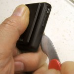
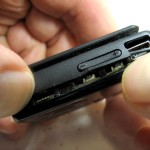
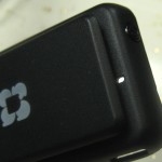
Here’s (one of) my shiny new $20 4 GB Sansa Clip+ MP3 recorder/players from Woot.  It’s smaller than I’d pictured – but that’s fine.  The little “R” melted into the back of the clip might well mark it as refurbished, but I don’t know.

The first step was to install the open source RockBox firmware.  That provides essentially all the features the hardware is capable of – far more than the manufacturer chose to expose.  It’s fantastic.  I even thanked them with a donation.

The only recording input is a built in microphone.  We have to open the device up to somehow get an external input to connect to where the mic connects.

A good tool to start cracking the case open was a watch case opener from a cheap set of watch repair tools from Woot or somebody.  After working carefully all the way around, I could peel it open.  I only broke one thin place near the USB connector hole.

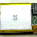
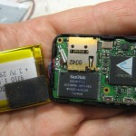
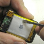
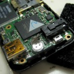
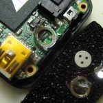
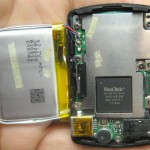
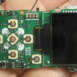
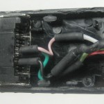
With the back off, the battery dominates the view.  The black headphone jack is upper right; the USB connector lower right.  There’s a screw that holds the PCB in place hidden under the battery, so we have to take it off.  There’s some double stick foam that holds the battery to a large chip.  Gentle peeling got the battery separated from the rest.  You can see the little mic at the right that we’ll have to remove.

The outside of the battery had two little strips of double sided tape – probably to make it really hard to get the case apart.  (It worked well!) After the battery was loose, those bits of tape stuck to everything on the bench, so I scraped them off, trying not to poke holes in the battery 🙂

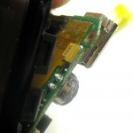
I managed to lift the PCB enough to see where the mic was soldered in.  I couldn’t get to those connections easily, and it was some trouble (and danger to the flimsy ribbon that connects to the display) to get the PCB lifted even this far, so I hoped I could get the connections I needed from the other side.  To do that, I planned to carefully destroy the mic, hoping to expose the two pins on the other side of the board from those solder blobs.  If I could cut everything else away, I could solder to those pins without needing to pull out the PCB.  Since I’ll very likely do this same hack to more of these great devices, I’d like it to be as safe and easy as possible.

Dissembling the mic started by peeling off the dust cover.  The aluminum case had no seams at this level – so it’s time to cut it open.  Eventually I could see the solder points I was after, but it didn’t seem like I could remove enough to use them.  Bummer.


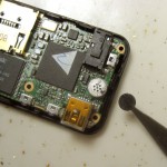
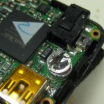
Back to Plan B – soldering to the back.  I carefully heated the 2 solder blobs (at the same time) and pulled what was left of the mic off.  I ran some wire scraps through the holes to clean them out.

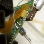
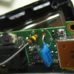
OK – what do I connect to it?  The little electret mic certainly has DC to power it, so I’ll need a series cap.  There’s often a 1-2K resistor as a load for the mic, so that’s probably about the input impedance.  Taking a wild guess, I decided I’d try 100K in series to drop the signal to more like what a mic input would expect.  I soldered a cap and a resistor to the old mic pads.

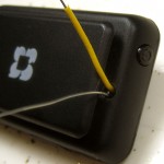
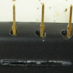
This is still prototype, so while eventually I need a cable with a good strain relief, all I needed at the moment was to get the wires out of the case.  The hole for sound to reach the mic was (obviously) right in front of where the mic was – which was also where my new leads were.  I drilled the hole out a little bigger, and relieved part of the top of the clip right there as well.  I brought the resistor lead and a bit of wire soldered to the short cap lead out the hole and snapped the case back together.

I pushed the button – and it still powered up – a good sign.  I used the USB connection to drop a couple of MP3s on it, and they played nicely.  Then I stumbled through the menus and figured out how to get it into record mode.  (Yeah, it’s probably in the doc somewhere.)  Some such recorders will run in full duplex mode and let you hear on the headphone output what’s going into the record input.  I put some audio into the wires on the back – and sure enough, it came out the headphone jack.

My interest in that feature was to test whether the device had AGC.  By listening to the output while varying the input level a lot (20 db or more) it’s easy to hear whether there’s any AGC leveling the output.  I did that test, and (a little to my surprise for a voice recorder) the Sansa didn’t seem to have AGC (at least under RockBox).  Not a problem – that’s what my recording preamp/AGC/limiter is for.

With audio coming in and a little fiddling with the input level and the gain control in the recorder, it was recording!  RockBox let me set the sample rate and bit rate to my customary values (44.1KHz, 96Kb/sec, mono).

As a sanity check on the input level (and whether my 100K guess was in the ball park), I ran some audio through my good white recording preamp, set to normal level according to its LED meter.  Its output went to the Sansa input.  A little fiddling with the gain in the Sansa, and I could get ideal record level.  The 100K was at least an acceptable value.

A test that remains is to see how long it will record on its internal battery.  That will give me some insight into what I would need as a massive single battery to last a whole weekend.

As an added and welcome bonus, the Sansa even timestamps the files it records!  My stalwart Iriver 800s don’t do that.  I think some other model does (maybe a T30??) but that one had other fatal flaws.  This one has it all!

My hat is off to fellow square dance recordist Ray Olszewski from Palo Alto who tipped me off to these great recorders (some hacking necessary).  His Altoids-box-housed recorders piqued my interest, and when I asked he told me all about them and the mods he and Bill Hoover had made to them.  Thanks Ray and Bill!

With the exception of final mechanical dressing of the input lead – which should be easy – this hack as been a total success!

Update 9/20/11: Did a battery test with a freshly fully charged battery, recording at 96Kb/sec continuously.  Incredibly, it recorded for about 14.5 hr, consuming just under 600MB (of its 4 GB!).  Source was a ~15 min recording with 11 sec silence at the beginning continuously looping, played on an Iriver 890.  While it did split each loop of the playback to a separate file, I haven’t gotten the trigger stuff to work right yet.  But I haven’t put a lot of time in tweaking it yet.  I expect I’ll get it to do just what I want.  Level is maybe a little low – that 100K may need to be cut to 50 or 22K.  That’s easy.

Very interestingly, even with less than a new battery, that would be enough recording time to do a full day without even shutting it down between sessions – even in the worst case hum/noise scenario!  If I do integrate it with a bigger battery (that also runs the recording preamp/limiter), it looks like it won’t have to be a huge one.  One of the real hassles of recording in multiple halls is running between halls at the end of each session to shut down – and then again to turn them on before the next session.  If I can just leave them running, that’s a huge simplification of my duties.  I’m happy enough to set them up before the first session and take them down after the last session each day to dump recordings and recharge batteries.  This is about perfect!

Update 10/15/11:  Having decided to remove the battery from the Sansa housing and provide a single “large” battery to power both the recorder and the electronics, I needed to be sure I understood what connections I’d need to the Sansa.  Two questions:
– Is the ground end of the mic input really connected to battery minus?
– Will it play (very likely) and charge happily (the real question) if the 3rd (blue) wire from the battery is disconnected?

That third wire is usually connected to a ~10K negative temperature coefficient resistor in good thermal contact with the battery so the charging circuit can abort if the temperature is too high (or possibly too low).  The other end of the resistor goes to battery minus.  The battery pack I’m planning to use (an 850 mA-hr unit from Spark Fun) only has 2 wires, so I care about whether that’s enough to get the Sansa to run.  But since I’m also hoping to use the Sansa’s charging circuit (even though the new battery is 3 times the capacity of the original), I might need to spoof that NTC resistor if the charger won’t charge without it.

So I opened it up again, first checking continuity to the low side of the mic.  The first test was whether I’d see battery voltage between B+ and mic low.  I did!  So there’s at least a pretty low resistance DC path from mic low to B-.  With that reassurance I used a continuity checker and verified a very low resistance between the two.  Great – that’s one fewer wires I have to bring into the Sansa – and since the low side of the audio of the preamp is at ground/B-, I don’t have to worry about connecting them.

Then I unsoldered the blue wire from the battery.  It still played, as expected.  To determine whether it would still charge, I measured the voltage across the battery terminals before and after plugging the USB connector into the PC.  The voltage went up – so yes, it’s charging.  Perfect.

Since I’m already putting a cap on the output of the preamp, I just added a resistor to the board, and now I don’t need any additional parts inside the recorder.  And since the low side of the mic is really B-, after I pull the mic, I only need to solder one wire in – to the mic high side.

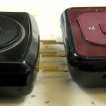
After considering various connectors, I decided that this would be a dedicated device, and essentially always connected to one of my preamps.  That let me take the easy way out and just provide 3 normal 0.025″ square pins coming out of the bottom of the device.  By providing good mechanical mounting for them inside, those 3 pins can become an integral part of the mounting mechanism for the Sansa.  Unusual, but completely workable for this application.

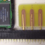
To use a single battery for the electronics and the Sansa, I removed the battery from the Sansa.  I only need 3 connections out of the Sansa:  Ground, V+, and Audio In.  Removing the battery gives me a place to mount a little PCB with 3 normal 0.025″ square pins sticking out the bottom of the unit.  The pins are on 0.1″ centers, but skipping 2 pins between each, giving 0.6″ between the outside pins.  These pins will be a primary part of the physical mounting, so having them farther apart provides a more secure mount.  I left a generous amount of copper for each pin to provide good mechanical strength from the soldered joint.

I measured the pins, how far they should stick out to plug comfortably into a female header strip (0.25″), where the board would be located in the Sansa, and included a mark on the PCB layout for where the end of the pins should be.  As long as I was making up a board, I laid out 3 copies, and found a scrap of board that would just fit.  Too lazy to make another board holder for etching, I just bent an existing one (from the LED display latch boards) to fit this one.  Worked fine.

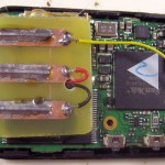
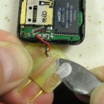
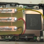
To ensure correct alignment of the pins, I plugged them into a female header to hold them while soldering.  Here’s the unit with new leads for battery + and – and a yellow one from the old mic location for audio in.  A little hot melt to hold the board in place, and we have electrically and mechanically sound pins!  (A keen observer will notice that the board obscures one of the screw holes.  I didn’t, but was able to clip the corner of the board so I could put the screw back in.)

Sorry about the ugly holes.

When I modified the second Clip+, I was sloppy when I pressed the little PCB down on the hot melt, and it ended up crooked.  I had little choice but to removed it and reglue it.  Guess it was a good thing I used hot melt instead of epoxy.

OK – that was on one of the (4GB) Clip+ devices I got from Woot.  There’s also a regular Sansa Clip, with no micro SD slot.  If those work as well, it increases the collection of Ebay offers I have to choose from to get more.  I got one and took it apart.

The physical layout is a little different, with a combo hold/power switch, and a shield over almost the whole main board.  The battery is still glued (double sided tape) to both the guts of the unit and the case, continuing to make it a challenge to open the case the first time.  After you remove the battery and pull the (slightly differently laid out) screws that hold the main board, the display stays on the main board, so getting to the mic solder contacts is much easier.

The shield (at least after roughing it up with a bit of sandpaper) makes a fine surface to glue the little pin-holding PCB to.  I did have to cut off one of the plastic hooks that lets the case snap together.  Overall the Clip is probably more desirable than a Clip+, between easier access to mic solder points and possibly being a little cheaper from being a little older and lower functionality.
One thing I didn’t see coming was that that shield in the Clip is not at exactly the same height as the SD card socket I was gluing to in the Clip+.  A little judicious bending should fix it, but it was a surprise the first time I tried to plug the Clip into one of the recording preamps into which the Clip+ fit fine.

While the original two units had their pins coming straight out, to be plugged into a hacked down socket, I think later units will have the pins bent to be essentially flush with the back of the Sansa, and I’ll just solder them to the recorder PCB.


Posted in Recording preamp/limiter | 7 Comments

New PCB etch exposure stuff

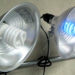
While my dear old 18″ UV fluorescent tube setup for exposing sensitized PCBs works fine, it’s pretty clunky.  I found a 13W black light CFL bulb and thought it might make a more convenient setup.  Since the manufacturer says the board material can even be exposed with normal fluorescent lamps, and since I had two new cheap clamp-on reflectors and 27W (100W equivalent) daylight CFLs for closeup photo shoots, the experiments to try became clear.  Will that big honking daylight CFL or the new BL be my new exposer?

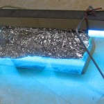
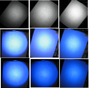
Of course for larger boards, part of the question is how uniform the illumination is.  Reasoning that the relative brightness distribution of UV and visible light should be about the same, I hung a sheet of paper in front of the two lamps to try to get a handle on it.

As expected, it’s brighter in the center.  I played a little with trying to get quantitative comparisons with brightness measurements of the digital images, but there were so many translations in there that I didn’t pursue it.

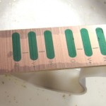
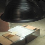
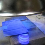
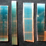
Since it’s board exposure that matters, I made exposure test strips at the center and near the edge of reflectors with each of the two bulbs,  all about 2″ below the bottom of the bulb.  The bulbs were warmed up before starting, and exposures were 2, 4, 8, and 16 minutes, moving a cardboard mask to cover up progressively more of the board after 2, 2, and 4 minutes, finishing 8 minutes after the last move.  I (marked the board scraps! and) developed them all at the same time and for the same duration.  From L to R: daylight center, outside, BL center, outside.  It’s positive-acting board, meaning black in the artwork produces copper in the result.  So unexposed areas remain covered with resist, while exposed parts have their resist “developed” away.  Most exposed part is at the bottom of each.  The steps are not really visible, though the overall effect is. There was one extra test in that the long skinny daylight edge strip had maybe its top 20% not covered by the glass, essentially making the two 2 minute exposures – with/without glass.  Since glass typically doesn’t transmit UV very well, there is question of whether the glass increases my exposure times.  I couldn’t see any difference at the 2 minute exposures they got.

Unsurprisingly, the edge strips were visibly less exposed than the center ones.  The BL generally provided more exposure, so I decided to go with that one.  The approach for larger boards – maybe more than 2.5″ square – will be to move the boards a few times during exposure so each end or corner gets some time in the bright middle area under the bulb.

Based on seat of the pants evaluation of the exposure strips, I guessed with the BL bulb maybe 2.5″ away (for more uniform illumination) I should go for about 10 minutes for a board centered on the bulb.  I used that exposure for the first of the scrolling LED latch boards, but the finest lines nearly washed out – indication of overexposure.  Six minutes should be about right.  That’s noticeably quicker than the 10 minute standard I’d come to use with the UV tube, so the CFL BL and reflector will be my new standard setup.  And if I put the bulb in its plastic retail package it all should be easier to transport safely for demos.

Update 12/11/11:  After a few more boards and a few more slightly washed out thin lines, I’ve shifted to 5 minutes as my standard exposure time.  Seems to work just right, and is very pleasantly quick.

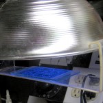
StandardExposureSetup9635Update 3/24/13: I’ve been using the little blacklight bulb in the 8″ polished reflector for all my PCB exposures for over a year now, and it’s just great.  I made up a quick and dirty board support from a scrap of clear acrylic that hooks over the edges of the lamp to provide constant BoardHolder9639distance from board to bulb/reflector with minimal effort.  Here it is with the usual sandwich of board, artwork (ink side down) and glass on top to hold the artwork in intimate contact with the board.

Also, driven by a need to produce a couple of prototype boards for Workshop88’s THOTCON badges, I tuned my process to give very consistent excellent results with 10 mil traces – which I’d never even attempted before.  The test artwork was 10 mil wide lines on 20 mil centers.  Success was exactly equal line/space widths after etching.  The final result was reducing the exposure time (with exactly the setup above) to one minute and 40 seconds.  Comes out perfect every time.

Posted in PCB Etching | Leave a comment

Etching board holder

I needed a better device to hold boards while in the CuCl2 bubble etcher.  The plastic shipping holders from the coffee packet system (Flavia) we use at work looked like they might be useful someday, so over the past year I’ve collected a lot of them from the recycle bin.  They’re 13.25″ long, pretty flexible, 30 mil thick, and can be bent with the flame of a match.  I pressed some into use for the holder.  I’ll make some more for other size boards, but I needed something good right now for the production run of latch boards for the scrolling LED display.

In addition to holding the board securely enough for the task, a big concern is that the holder can’t interfere with etching where it holds the board. Using the spring of the plastic and some minimal holes in the corners, I made a holder designed for these boards.  The possibility of a “shadow” where bubbles can’t wash the surface with fresh etchant (red) was minimized by cutting the holder back as much as I was comfortable with.

The board clips satisfyingly into the holder.  Another strip of the same material epoxied to the back to hold the board upright provides a holder/hanger.  Time will tell whether the plastic and epoxy will hold up to the acid etch bath.

Seems to be working OK.  Especially facing the production run of latch boards, it’s a delight to be able to set up and start an etch, set a timer, and forget about it.  I’ve done two “reloads” and the plastic and epoxy seem to still be intact, though the epoxy is a little stained.  The first board was completely etched when I checked on it after 20 minutes.  The second took more like 40!  After 20 minutes the top of the board seemed to be etched clean but not the bottom.  I kept giving it another 5 minutes, but finally flipped the board over.  The confidence that the etchant isn’t too nasty to skin gained in a demo at W88 allowed me to flip the board with my bare hands.  (I did wash them right after that.)  Another 5 minutes and it was done.  I infer the bubble pattern isn’t as uniform as it should be.  I flipped the 3rd board at ~25 minutes.  Top was done.  Looks like I need to do a flip at 10 or 12 minutes.  Boards all came out fine.

Etchant is very obviously “dirty” – brown with CuCl.  After 3 boards, it looks like between 4 and 10 g/l CuCl from Seychell’s color chart.  I’ll try to pay attention to how long aeration takes to clear it back up.

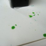
Interestingly, splatters on the white plastic base of the etch tank (dripped while removing/reloading boards) over time self-aerate, getting visibly closer to the clear green of etchant containing little/no CuCl.  (Very conveniently, droplets on the base work well to simulate Seychell’s “drop on a white card” test.)  This picture, taken a few hours after the etching was done, show mostly “good” green, with the one dirty green in the upper right the result of an earlier CuCl color test.  I’m sure that droplet was much darker when I made the test.

An additional observation is that there’s significant corrosion of at least ferrous metals in the vicinity of where the aeration takes place.  There was obvious rust on the side of a grinder near the etch bath, but none on the far side.  The near side was maybe a foot away from the etch container.  There was rust on other motor shafts and housings in the (crowded) area.  I don’t know if it was from early bubbling in an open container or the current setup.  In any event, it’s very obviously necessary to keep at least some kind of cover on the etch container, at least when the bubbler is on.  I just used a small plastic bag formed a little to make a drip point for the etching today, and put it back when I started aeration.  (To be clear:  I turned the air pump on when I started etching and never turned it off.  Of course some aeration was happening as a positive side effect while while the bubbles were doing mechanical agitation duty during etching .  “… when I started aeration” was when I pulled the last board out and stopped etching.)

Update 11/30/11:  It’s finally time for a new holder.  I’ve bent the original several times to fit various boards, and it’s still in one piece, but the first RF gun board is too big for it.  And I wanted to get away from the epoxy holding the board clamp and the support piece.

Construction is essentially the same (the old one worked!), but now the parts are held together with a couple of 6-32 nylon machine screws.  Should be fine.

Update 12/3/11:  Here’s the smallest board I’ve needed to etch.  It’s 3 instances of a breakout/mount for a Luxeon Rebel LED.  This is the original holder – re-bent several times and still working fine.  The epoxy is stained greenish, but still holds.  (The nylon screws in the holder above also came out yellow-green after one etch.)  This bend covers the corners more than the very first (and more than I’d prefer), but there’s a pretty big margin on this board and I don’t think it will be a problem.

I’m delighted with this material and approach.  First, it really works.  The plastic is just springy enough that it’s easy to insert/remove the boards, yet the holder is still very appropriately secure.  And it’s free – all scrap.  Can’t ask for much more!

Posted in Cupric Chloride Etchant, PCB Etching | Leave a comment

Root hacking

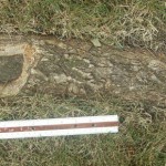
There’s a big chunk of exposed tree root that rises above ground level enough that I’m afraid the mover is going to hit it every time I mow.  I finally cut it down a bunch.

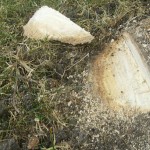
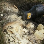
The original plan was to borrow Ed’s sawzall and take a horizontal slice off the top – maybe 3/4″ thick in the highest place.  There wasn’t enough clearance to get the sawzall in position, so I had to excavate on one side of the root.  Fine.  But for reasons I really don’t understand, the saw just didn’t want to rip through the wood.  Maybe I twisted the bade in the cut or something, but it just slowed down and the wood started smoking.  I made a vertical cut and took the little slice I’d started off.  The saw made the vertical cross cut like cutting through butter.  (Why wouldn’t it rip??)

But the exposed vertical edge inpired Plan B:  I got a hammer and wood chisel, and started making a series of vertical cuts down through the root.  Then it was easy to crack out big hunks with the chisel.  That worked very well, though it wasn’t always pretty.

I hacked quite a bit of wood off.  It’s probably at least an inch lower in the worst high spot, so I think the mower is safe for several more years.  I put the sod I’d removed back, watered it in, and it’s done!


Posted in Home Repair | 1 Comment

Recording preamp/limiter – with battery test

(Post rebuilt – see footnote.)

I’ve built several preamp/AGC/limiter boxes for square dance recording, each getting a little better than the last. (Well, the black one wasn’t so great.) I still aspire to a “perfect” device, answering all my needs. We’re getting closer now.

I need this device (maybe without single battery) for a couple of other recordists I’ve promised it to, so there’s some pressure to get it done.

Requirements/History

The ideal device would –

Just work. With one level set, NEVER distort or fail to record.
Be as simple as possible (but no simpler)
Not require AC power to reduce hum, provide quicker/easier setup
Accept any level from mic to speaker
Provide visual indication for setting the level
Have pigtails for input/output to reduce number of connectors
Create a new file for each tip, not recording the “silence” between tips
Have enough storage to handle at least a whole day, preferably a whole weekend
Have enough battery to handle at least a day, better a weekend
Have a battery test function
Be unlikely to accidentally turn on in it’s carry case.
Between “simple” and enough battery and storage, be an appliance I could hand to someone going to a weekend to bring back problem-free recordings. I’d be happy to write doc to support that use.
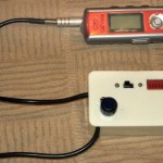
My best current device – the white one – is simple and reliable. The power switch at the end of the level control has a fairly stiff detent and along with a small diameter knob rarely turns on accidentally. Its 9V battery will run it for a couple of weekends, but the battery test indicator is a mechanical switch. The battery in the recorder is separate, and not reliably enough for one day. The 256 MB recorders I’ve been using aren’t enough for a whole day. It would still take a geek to operate it at a weekend. Still lots of room for improvement.

Several years ago I found a great chip – the Analog Devices SSM2165. Designed as a mic preamp, it has programmable AGC, and desperation limiting at the top end to avoid clipping. To avoid the problem of huge gain amplifying background noise when there’s no program material, it also has a noise gate. That implements a threshold below which input is attenuated rather than amplified. The effect is that with input below that threshold, the output is essentially silent.

They discontinued that great chip, with the tiny 0.5mm pitch SSM2167 as the replacement. I finally figured out how to solder that, discovered that it clips (!?!) on large peaks, sidestepped the clipping by hacking some more headroom in by reducing signal level between sections of the chip and not running it on 3V. Fought battles with recorders and have settled on the Iriver 800 series. They seem to have a little better battery life than the 700s, and might last a day on one AA. The 512MB models will handle a whole day unless we run into the “hum/noise problem”. The only shortcoming is that they don’t timestamp the files they create. That would be nice, but its absence is not a showstopper. There’s the possibility of trying to add more memory to these guys, but that’s a whole nother project.

Battery issues

The current separate preamp and recorder setup requires two batteries. If either fails the system fails. Ideal would be a single (big honking) battery that I can make as big as I need. Unfortunately, the recorders need 1.5V (a AA) and the preamp needs at least 5V. I could use a 5-6V battery and a regulator to get the 1.5V for the recorder, but that’s not very efficient. I found a tiny DC step-up device at Pololu that will take 1V or more and put out regulated 5V. While it is not 100% efficient, I think the preamp is the lower power draw, so that should work, letting the main battery be 1.5V. To power the recorder from that battery I’ll need a fake AA with a pigtail to put in the recorder.  And since it’s not designed for external power, I have to somehow tie the recorder down so the fake AA doesn’t fall or get yanked out. I think I can do something cool with Shapelock to make a snap-in holder. But now I can put in enough AAs (or Cs!) to last as long as I like and still have good 5V for the preamp. So that’s the plan for the new version.
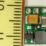
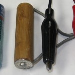
The larger problem is a battery level meter. The obvious way to display it is on the 10 segment display from the 3914. In early versions I used a DPDT switch to switch both the signal (AGC or battery) and some of the range/offset voltages going to the 3914. After some problems with reliability of the small slide switches I used, I’d like to avoid using them. Ideal would be a momentary SPST. CMOS analog switches should allow switching as many things as needed.

But the real problem is getting a linear indication of battery capacity remaining with the NiMH cells I most always use. The (unproven) plan is to put in a low power micro with A/D input and D/A output to read the battery voltage, do a table lookup, and put out a voltage to drive the 3914. I think I can do it with an ATTiny85. It has a 10 bit ADC in and 255 step PWM out. The single momentary battery test mode SPST would provide power to the Tiny and somehow control the CMOS switch. Since the discharge curve of alkaline and NiMH cells is very different, it would probably need a jumper or something to set which battery chemistry was being used.

To get the best resolution in, I’d like an analog reference around 1.6V. I could use a resistor and zener (powered by the battery test SPST button), but it’s extra parts. The Tiny has an internal 2.56V reference. The battery voltage range of interest is maybe 0.95 – 1.5V, which would come out with ADC values from 380 to 600. Tossing the low bit, that still gives me 110 values for the range of interest. Not ideal, but it should work. For 2 more resistors, I could divide the battery voltage down so it would fit with the other internal reference of 1.1V. But that would draw constant current. Hmm – what if the battery test button switched ground to the Tiny instead of power? No, the Tiny would have +5 at the top and +1.5 – through the divider – at the bottom. That would probably be enough to power it, which we don’t want. Maybe the 2.56V ref is good enough.

On the output side, I should be able to create a (noisy, PWM-based) voltage from 0-5V in 255 steps. When the 3914 is tuned for the AGC voltages of interest, the range is roughly 0.38-0.68V. (Well, that was the range with the 2165. I expect the 2167 is similar enough for the ballpark calculations here.) If I scale the 5V max PWM output down to 0.68V, the range from 0.38 to 0.68V is PWM counts of ~137-255. That’s ~118 values. If I throw out one bit, I’ve still got 59 steps. Since the 3914 lights one of 10 LEDs, I’ve still got ~6x the resolution of that device. Works on paper – wonder if I can make it work in real life? The fact that I can tweak the lookup table arbitrarily is encouraging.

Update 9/16/11:  If I end up using that sweet Sansa recorder, things change a little. That runs off a little 3.7V Li-Po. The one that’s in it is 290mA-hr. I found some up to 5000 mA-hr that should let me use the original approach. The little DC booster will accept the 3.7V in. If the Sansa will run down to maybe 3V, I could use 3 NiMH in series. More investigation needed.

The battery indicator in the Sansa is calibrated for a Li-Po battery. If I use one of those, maybe I can just skip putting a battery level indicator in the preamp completely! The indicator is visible while recording, so it could be checked at any time.

But that doesn’t change the issue for using the preamp with non-Sansa recorders (of which I still have several!). And there are still two flavors of those: Stand-alone preamps for others (Les, Ron) that will probably have 6V batteries; and one for my 1.5V Irivers with 1.5V batteries. So there are really three versions of this preamp. No wonder it feels like I’m stalled on it!

The “hum/noise problem”

I can control the size of the battery, and buy recorders with enough storage to do whatever I need. And while it does require one manual level setting, if noted that setting should work for the whole weekend. The noise gate in the 2167 usually cuts the output during quiet times to low enough that the recorder reliably stops recording and waits for signal again.

But there’s one problem case I can’t work around (without a really major redesign of the system). If for some reason there’s a low level of background hum or noise, it may be low enough to not be a problem for the dancers – and in fact inaudible between tips unless you put your ear up to the speaker. But it can still be high enough to not be below the 2167 noise gate threshold, and thus be amplified enough to keep the recorder from shutting off between tips. In addition to adding a post-processing step of cutting the huge resulting file into tips, the recorder stays on, wasting both battery and storage. I can try to set the level a little lower and play brinksmanship to get the noise below the threshold without compromising the soft parts of the desired recording, but that’s a dangerous game.

I can overcome the battery issue (batteries are cheap), but storage is a problem. The ratio of active dancing to overall time is maybe 60%, so it results in almost twice the storage usage. But that’s not the biggest problem: I’d like to be able to not have to touch the setup between sessions. And if the hum remains on the few-hour breaks between sessions, the storage requirements go up very significantly. Now in practice the callers’ amp is probably turned off between sessions, so that worst case may be rare. But if I’ve given the setup to someone else to record a weekend I can’t attend, I could lose a significant amount of dance recording to this. If I cut the recording bitrate by a factor of 2 or 3, I could probably get by. And the lower bitrate recordings would still be usable – and infinitely better than no recording because it ran out of storage. But then I’m throwing quality away to hedge against an unlikely case. Ugh.

The Plan
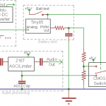
Here’s the current high level design. Single battery, micro for battery level, momentary SPST for battery test.

The main subsystems are the audio processing, power supplies, battery test, and the display.

The audio path consists of the input attenuator and 2167. I might add a little MCP6282 rail-rail opamp to give a little more output, making up for the signal loss in the headroom hack. Power to that chip(s) is through a main physical power switch, not shown.

Power is from an extensible battery of 1.2 V NiMH (or alkaline) cells in parallel. Their output directly powers the recorder through its fake AA cell. They also power the little DC step up board to get 5V for the 2167. I’d prefer 5.5V for a little more headroom, but the step up board I’m using isn’t adjustable.

Battery test mode is enabled with the SPST button. That powers the Tiny85 and flips a CMOS switch to route the filtered DC from the PWM output to the 3914. I may have to play with logic levels (maybe a pulldown) so the CMOS switch defaults to the channel with the 2167 AGC voltage. One remaining concern is whether putting 1.5V on an input pin of an unpowered Tiny will damage it. Needs to be checked out. If that’s a problem, I’ll need to dig into sleep states or something to keep the Tiny from eating much battery.

Not shown for the 3914 is a small network of resistors/pots to set the high and low ends of the range to match the 2167. May require manual calibration – or maybe just 1% resistors if I make a bunch of them. Those resistors also set the LED current.

I haven’t breadboarded the battery test stuff yet. It should work, but I hope I have enough sense to test it out first. Oops – I don’t have any DIP LM3914s. That’ll put testing off a bit.

Update 9/20/11:  OK, I’ve gotten the analog in and PWM/DAC output pretty much working with the Tiny85. There’s a sleep/wake I haven’t tried yet, but it should work.

Next step is finishing the board layout. I don’t have any SOIC Tiny85s, so the first board will use a DIP. Maybe with leads flattened and surface mounted to minimize layout change for the SOIC.

Possible major redesign


This isn’t any more than a thought at this time. Currently the user (potentially not me if I ask someone to record a weekend I can’t make) requires separately turning on the preamp, turning on the recorder and putting it in record mode. I could reduce the user interface to a single on/off switch and a level set if I embedded the recorder into the device along with a microcontroller that could operate the recorder. I found some cheap 1GB recorders (~$16) that I disassembled and started to investigate spoofing button presses on, but didn’t get too far. If I could do that, and if I put in my own signal processing to determine when to start/stop recording, I could implement a smarter noise gate that would figure out there was hum/noise and change its threshold to turn off recording between tips despite the noise. Lots of work. Maybe some day. Maybe.

Recorders

(Section started 9/3/11.) While not directly about the recording preamp, I’ll try to collect here my thoughts and recollections about various recorder hardware I’ve used with the recording preamps. For reference, the application is recording live square dances with the intent of producing very high quality recordings to play back for basement or “tape group” private dancing.
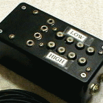
Patch box from krubow.com

Connection is direct to the caller’s audio system, with typically line-level audio either from the amplifier (usually Hilton) or from a “patch box” in line with the speaker cable, electrically in parallel with the speaker. Program material is mono. While near studio quality, these recordings are never sold – including by the caller – or used for public dances where money changes hands.
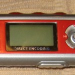
The first hardware MP3 recorder I used for square dance recording was an Iriver IFP-790. It has 256MB of flash and a line-in (or mic-in) jack. Audio quality is very good, and that has earned IFPs a reputation of excellent sound. They will record in mono (or stereo), doubling the recording time. They have an auto start/stop mechanism that starts new recording files with each tip, skipping the silent time between tips – exactly what I need. This recorder is red. Others in the family are the 795, a silver 512MB model; and the 799, a 1GB model (sorry, never had one and don’t know the color). I’ve gotten all my Iriver recorders used on Ebay. Appropriately, prices run higher for models with more memory. I’ve been paying $35-40 for 256MB recorders (790/890).
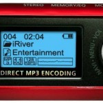
An updated Iriver family is the 800 series, with a red 256 MB 890, a silver 512MB 895, and a 1GB 899. The 800 cases are a little larger, more rounded, and have some connectors moved around. Functionality is just about the same, but I think battery life while recording is a little better. Both 700 and 800 series use a single AA cell – primary or NiMH. Most of both families also have an FM radio built in, though that provides no value for my uses. A significant drawback to both 700s and 800s is that there is no record level indicator in the user interface. It is that shortcoming (along with lack of AGC on line-in recording) that has forced me to design the recording preamp this note is about.

There are 2 major families of firmware for these 700 and 800-series recorders. The original would only connect the the Iriver Music Manager software running on a PC (don’t know about MAC/Linux). The other, called MSC makes the recorder look like a USB thumb drive. A limitation of the USB drive versions is that the highest MP3 bit rate it will record is 96Kb/sec, and opposed to 128 (or 160??)Kb/sec for the Music Manager version. Both are at 44KHz sample rates. Lower sample rates and bit rates are also supported. After some moderate experimentation years ago, I found I couldn’t hear any difference above 160Kb/sec for stereo recordings (though 160 was better than 128), and so have standardized on 160 for my home stereo MP3 library. That’s like 80Kb/sec for mono. While I’d record at 128Kb/sec if I could, 96 still gives me a little quality headroom so when I resave at my standard 80Kb/sec after normalizing volume and doing some minor editing I probably haven’t lost much fidelity.
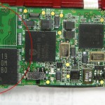
At least the 800 series devices have places on the board for 2 memory chips. I’ve looked pretty hard for the Samsung chips they use, but have never found any way to buy them. There are 256 and 512MB versions of the chip. I have a dead 790 (power supply burned up while trying to measure current draw using a bench supply – ouch) and I’d like to try putting its memory chip into another device to see if it would recognize it and give me 512MB. The SMT rework would be a challenge, but I think I can do it. I’ve bid on dead 512MB devices, hoping to scavenge the memory and build up a 1GB device, but never won any. I haven’t actually moved any chips yet.
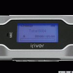
Another Iriver model I’ve tried is the T30. I’ve had a red 256MB and a silver 512MB version. This runs on a single AAA cell, limiting its recording duration in my set-it-and-forget-it application. It also will auto start/stop recording, but records in stereo only, essentially cutting record time in half for a given memory size (read: cost!). I also have had some problems with auto start/stop reliability on this model, though that might be my fault. On the plus side, these recorders (maybe only with Music Manager firmware?) put time stamps on the recorded files. I wish the 700/800s did that! In any event, that’s enough strikes that I don’t bother with T30s any more. I haven’t sold the ones I have yet, but I should/will.

I think I tried another lower model – maybe IFP 300 series? – but it didn’t have enough features (no auto start/stop? no mono?) to be considered.
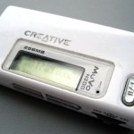
I also played with a little Creative Muvo N200. It uses a AAA, and didn’t work well for my application. Maybe no auto start/stop? Anyway, it was kind of a non-starter.

I also found a non-name brand 1GB recorder I could get for ~$16. It had limitations, too, but for the price was considered for hacking into an embedded recorder. I took it apart with the goal of hooking wires to the critical buttons on the user interface, but never got very far.

I ran into a guy recording at a couple of weekends using Sansa recorders. He had hacked into the recorders to put in a line-in jack from where the internal mic was connected. He was running the open source RockBox firmware, which provides excellent and flexible access to most everything the recorder is capable of – usually much more than the manufacturer’s firmware provides. He had built them into Altoids boxes, and had a couple made up for recording in multiple halls at large dance weekends.
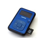
I just ran across a 4GB Sansa Clip+ on Woot for ~$20. I checked, and RockBox is well supported on that device. It will require a hardware hack to get a line-in jack, but if it works well it will completely resolve the issue of recording storage in the face of the hum/noise problem with just the internal 4GB. And it supports a micro SDHC in addition! Battery is 3.7V (LiPO I expect) and not intended to be replaceable. I ordered two of them, and will report more as I learn about them. I do have high, if slightly guarded hopes. Wow – open source – I wonder if I could use RockBox to embed a recorder and control it semi-remotely?

LM3914 Programming Resistors

To avoid having to look up / figure out this nonsense every time I do a new board, let me put it all down here for reference. For example values, I’ll use the typical 3mA LED current and a range of 0.3 – 0.68V, about what we see on the 2165′s AGC averaging capacitor.
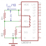
We use the magic reference source to set the voltage at the top of the dividers that set the range (Rhi). Details of that follow, but assume we have our 0.68V at Rhi. The internal divider chain is 10 x 1K. We need the bottom of that chain to be at 0.3V, so R3/(10K+R3)=0.3V/0.68V. That gives about 7.9K for R3. Since we’ll need it later, there will be 0.68V/17.9K=0.038mA thru the chain.  Note: pic at right is wrong.  RHI goes to ADJ, not VREF.

Each LED will be provided with 10 times the current out of VREF (Ref Out). Since we want 3mA LED current, we want 0.3mA out of Ref Out. That current must all go thru R1. Since the magic reference always provides 1.25V between Ref Out and Ref Adj (ADJ), we’ll have 1.25V across R1. Its value then must be 4.17K. Ugh. How about 4.7K? That would give 2.65mA for the LEDs. Should be good enough for a first pass.

Now the magic reference source adjusts the voltage on Ref Out as needed so about no current flows in/out of the Ref Adj pin. That design characteristic of the reference source means whatever current flows through R1 must also flow thru R2 (well, and the internal divider chain). The voltage across R2 is the 0.68V we need on Rhi, so R2 would be 0.68V/0.265mA=2.57K.

But unsimplifying, the current in/out of Ref Adj isn’t exactly zero: That pin sources a fairly constant 0.12mA. So we have 0.265+0.12=0.385mA flowing thru R2 and the divider. We saw above that the divider sucks up 0.038mA, so the actual current thru R2 is 0.385-0.038mA, or 0.347mA. So the real design value of R2 is 0.68V/0.347mA=1.96K.

To allow for a little tuning (like if the 0.3 – 0.68V range isn’t quite right) we’d like to be able to adjust the voltages at the top and bottom of the internal divider independently. Adjusting the bottom is easy: make R3 variable. A 10K pot should be ideal. And since the current thru the divider is fairly small compared to our 0.3mA of LED programming current, small changes due to tweaking that 10K can probably safely be ignored.

To adjust the voltage at Rhi, we could make R1 adjustable, R2 adjustable, or put a pot between R1 and R2 with Rhi/Ref Adj on the slider. Adjusting R1 directly also changes the LED current, and while that’s not critical, that’s not ideal. Making R2 variable changes only the voltage at Rhi/Ref Out – ideal. (Well, and small proportional change to Rlo.) And if we make it 5K, we’re about mid-range – great!
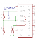
I did a quick test, and this probably “final design” works:

And now I should never have to think thru it all again!

(Later) While all the logic and math above is correct, the initial assumption that the 2167 and 2165 voltages would be about the same was not. Appropriate voltages for the 2167 are ~0.55v – 0.82V.

Update 6/5/12:  For the record, here are the final resistor values (shooting for ~0.82V and 0.55V).  I don’t want to have to tune pots in each copy of the preamp I make, so I’ll use fixed values.  For the LED current determining resistor between pins 7 and 8, 4.7K works fine.

To determine the RHi voltage, I laid out 2 resistors in series between pins 6/8 and ground.  Target value was 2.7K.  I don’t have any of those, but 1K plus 1.5K seems to work OK.  I got ~0.795V in the instance I checked.  For RLo, I laid out 2 resistors between pin 4 and ground.  I think the design value was 24K; I ended up with a 22K plus a 2.2K.  At the low end of the scale if the bottom LED is lit, we’re just slightly above the noise gate.  I think if I get some 2.7Ks, it will move both voltages up just a smidge, slightly improving the tuning.

First version: for Sansa Clip+

(Updated 10/20/11) Time is getting really short to get this done before the next square dance weekend (Heartland, in a week). I’ve narrowed my sights to just making a couple of boards specifically for the little Sansa recorders.

To use a single battery for the electronics and the Sansa, I removed the battery from the Sansa. (More details in the Sansa Hack post.) I only need 3 connections out of the Sansa: Ground, V+, and Audio In. Removing the battery gives me a place to mount a little PCB with 3 normal 0.025″ square pins sticking out the bottom of the unit. The pins are on 0.1″ centers, but skipping 2 pins between each, giving 0.6″ between the outside pins. These pins will be a primary part of the physical mounting, so having them farther apart provides a more secure mount. I have some old wire wrap sockets which when cut in half and mounted sideways should hold the Sansa just enough off the board to clear the components beneath. Some hot melt at the opposite end will complete the Sansa’s semipermanent attachment to the PCB.

Housing will be an Altoids tin – with a little window in the top to see the LEDs and the Sansa display. There’s enough room for everything, but to get to the USB connector on the Sansa I’ll have to kind of lift it out of the box. Current plan is to make some kind of semi-official hinge at the end of the PCB. I’ll need to pay some attention to the thin coax audio input cable so the flexing of raising the board on its hinge won’t cause problems.

The board is finally done – still sort of a prototype. There’s a programming header to tweak the firmware on the Tiny85, and the Tiny itself is an old school DIP with pins folded under to surface mount it. The whole assembly is still quite thick.
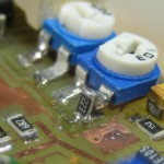
(later) Board is now assembled and tested. The bad news is that the max/min averaging cap voltages I need the 3914 to cover aren’t the same as what I had recorded for the old 2165 chip. Instead of 0.33-0.68V, it’s on the noise gate threshold at ~0.55V, and the front end (not the VCA) starts to clip (with music) at ~0.82V. I can’t hit the 0.55V with the 5K pot on the board. I unsoldered one end, bent it up, and fitted a 22K 1206 resistor on end between the pot leg and the board. Really ugly, but now I can set the 3914 to the voltage range I need. And now the whole thing works! The other bad news is that it’s too tall to fit in the Altoids tin. Off to the Container Store.

Wow – they have a lot of good candidates for project boxes there! I found some that were considerably larger than I want or need, but will suffice for the rapidly approaching weekend. The good news is that with the generous box I won’t need the extra complexity of hinging the PCB. I can get to the Sansa’s USB connector with it glued flat in the box, and I can still get to the power switch on the top of the Sansa. One down, one to go!

But first, the board needs to have a nice home for that 22K resistor. And let’s try some SMT LEDs instead of the big clunker bar display. And since some of the caps weren’t the size I thought and were a hassle to solder in, let’s change the board for the correct SMT packages. And as long as I was in there, I moved several components around a little to make the traces less convoluted. With the updated artwork, I made the second board.
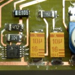
But when I first fired the board up, it wouldn’t record. The LEDs danced appropriately to show signal was coming in – but nothing was going out to the recorder. With that info, I soon found I’d made a boo-boo on the board: Of 2 big caps right next to each other, one had one end grounded, the other didn’t. But as I moved them around and updated package sizes, I incorrectly slid the second one so it was also on a ground trace. Fortunately, cutting the trace on both sides of the cap fixed it, and with further good fortune both sides of the trace were connected elsewhere, so I didn’t even have to jump around it.
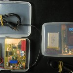
With that hack the second preamp worked, too. Here they are. I took the recorder out of the first one so you can see what’s under it. The little brighter green PCB just abouve the blue Sansa socket is the Pololu 5V DC-DC converter. The 3914 is obviously next to the LEDs; the quad CMOS switch is at the top; the Tiny85 8 pin DIP is next to its programming header; and the real brains of the outfit, the 2167, is the tiny chip next to the cap I had to cut traces around. The (green) SMT LEDs are a lot smaller than the red block on the first one, but don’t really let me make the board much smaller. Unfortunately, both LED arrays feel upside down: Highest volume is the LED at the bottom. Boo.

While the cases are twice as wide as I need, I really like the fact that the box protects all the controls when the top is closed. I’ll keep that feature somehow in the final version.

Here are all the recording config options I think matter:
Format: MP3 Bitrate: 96K Freq: 44.1KHz Source: mic Channels: mono
Prerecord time: 3 s Trigger: repeat Trigtype: stop
Start above -27dB for 0 s Stop below -32dB for 15 s Presplit gap: 15 s
Peak meter release: 1 u hold: 500ms Log scale, -50 to -6 dB
General settings->System->Start screen: recording
Recording screen->Gain: -3dB

Update after the weekend:  The preamp/recorder combos both worked flawlessly. I started them before the first session in the morning and collected them after the last session each day. No more running around like a crazy person to collect or at least turn them off between sessions. Hooray!

Well, almost flawless. The average recorded level was ~-31dB, maybe 10dB lower than I’d like. Yeah, I can normalize it back up, but it’s an extra step, and I’d like the recorder to get it right in the first place. Unfortunately, if I increase the Recording->Gain (not Volume – that’s playback output) even to 0 dB, it clips on peaks. Hmm – it’s open source. I wonder if I can make a private version that gives exactly the level I want?

Update 6/5/12:  This post was rebuilt from an old backup I was very lucky to find.  The whole post had somehow been deleted.  It used to be page 1611.  There are some details here.
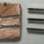
Posted in Recording preamp/limiter | Leave a comment

Old Palm as serial terminal

As I started setting up to use ATTiny85s with Arduino IDE and ArduinoISP as programmer, I quickly came across the “How do I get debug output?” question.  While the chip doesn’t have a UART, there is a Tiny Debug Serial package for it, so Serial.print() can bit-bang out PB3.  But what do I display it on?
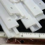
I could use an Arduino to take serial in and send it out to the serial console.  But I’m not sure I can do that and keep the ArduinoISP sketch in place – which I’ll need frequently to download new code versions.

I considered getting a serial LCD as a general purpose display, but they’re a little expensive, so I thought about what old stuff I might repurpose for this.  My old Palms!  I have a Treo and a Centro that got outdated before they got broken.  They’re real bored these days, and have serial I/O, so I started digging.

The two devices both use the Palm “MultiConnector” and the same cables.  Here’s a doc with pinouts.  The serial is 3.3V TTL.  Of the various cables I have for the two, only one has physical pins in positions 10,11 where the serial is.  I took it apart, and found those pins were not connected.  (It only had USB wires Gnd, +5,  Data+, and Data-.)  But there are enough wires, so I should be able to move some.

Done!  The range of small pins (L to R from the back) is 17-5.  White and green are now on 11 and 10.  The original black – via one of the yellows – goes to 8, so I’ve got ground.  After it’s all done it looks a lot like it did before I started.  But now white and green ring out to the RX, TX pins :).

The Tiny Debug Serial package included with current tiny 45/85 Arduino cores is almost a drop-in for the normal Serial stuff, automagically figuring out if the target chip has no UART and slipping itself in.  The package is send-only, but that’s really all I need.  Just added a Serial.begin(9600) and some Serial.print()s, just like normal.  I added a startup message and print the value read from the ADC once/sec.  The analog in pin is currently hooked to a pot for testing.

I found an old Palm Hotsync manager and reminded myself how to install stuff on Palms.  Found, downloaded and installed (free) ptelnet-0.61.prc to the Centro.  Got it running on the serial port at 9600 and hooked Gnd/RX of the new cable to PB3 (pin 2) on the Tiny.  Since the Centro is 3V logic, I used a 3.3K/10K voltage divider from the Tiny pin to protect it from the 5V logic levels.

And it works!  I’m just using the built-in 8MHz oscillator divided by 8 for a 1MHz clock.  Seems to be accurate and stable enough to run at 9600.  Woo hoo!

Now that it actually works, I terminated the cable for convenient use with a breadboard.  It’s even labeled for TX and 3 and 5 volt RX.  Hmm, seems to need a pullup to work.  I don’t understand that, but it works.


Update 8/30/11:  I have another Palm, so I’d like another cable.  The hot sync cables lying around have the wrong pins populated.  They needed USB, not serial, and so populated positions 5-8 and 12.  Let’s see if I can move some.

I opened up the connector and found a little PCB to hold the switch – no surprise there.  But the pins seem to be soldered to both sides of the board.  How’d they do that?  And how did they get spring-loaded pins in there in the first place?

After meeting the challenge of unsoldering the board without doing too much damage to the pins (though the plastic suffered a little) I gingerly pulled a couple of pins out.  That answered both questions:  Clever manufacturing provided the spring.  And the pins are reversible, with the solderable finger offset from center by about half a board thickness.  The good news is that I can just pull them out and relocate them to the positions I needed.  The other good news is that I can take advantage of the pin offset to give myself a little more working room on the two adjacent positions (10,11) I need pins for.

Of course the existing wires (molded into the strain relief) were too short, so I had to extend them before I could connect to the moved pins.  And let’s hear it for heat-shrink!

I only needed 3 pins (Gnd, TX, RX; 8,10,11) but I put the extra pins back in so I’d have them if I needed to disassemble it again.

A quick test and it works!  Haven’t terminated the other end yet.

Update 1/19/12:  The goal of this project was a cheap, simple way to get serial debug info at TTL levels from a micro on a breadboard.  I’m now using another approach that mostly works better for me.

While the Palm is cool and portable, it has a couple of drawbacks:
* The connector is flaky.  I have to keep pushing it in to make sure it works.  I think what I did is OK, it just doesn’t snap very securely into the Palm.
* The terminal emulation I’m using responds to BREAK (line not held high) with an error popup and stops.  I have to clear the error and then click the tiny On button to go online.  Power cycling the micro produces a BREAK condition – and it’s a hassle.  Another terminal emulation would probably work more gracefully, but I never got around to finding one.
* Since it’s battery powered, I feel like I have to turn it off all the time except when I’m actually looking at it.

My PC has several real RS-232 ports, so if I had a TTL to RS-232 converter, I could just run a terminal emulation in its own window and overcome all the problems with the Palm.  Not very portable, but I’m in front of the PC most of the time anyway.  Yeah, I could make something with 1488s/1489s or a MAX232, but there’s still the issues of power and 3.3 and 5V devices.

Taking advantage of the fact that most RS-232 implementations don’t actually require negative voltages on input, I used this cheap and cheerful approach:

It wasn’t even worth making a PCB.  Each side provides its own appropriate positive voltage.  The RS-232 end (PC) must assert DTR true to get a positive voltage source, and by connecting the TTL side to local power on the breadboard – 5 or 3.3V, it works happily with either.  And no external power required!

I’m still happy to have my Palm and cable as a backup, but this is now my main serial TTL tool.


Posted in Palm Serial Terminal | 3 Comments

Sump pump current sensor

This sensor has been part of the home automation system for several years.  It’s mounted to the wall, and the main AC sump pump is plugged into it.  It senses current to the pump, converting it to a logic level a PIC node can read.  Connection to the PIC is via the RCA jack on the side of the box.

The main component is a toroid with many turns of red and green magnet wire.  I hooked the red and green windings in series to get more output.  It might be an 88 mH choke from some telephone equipment, but I have no confidence that’s true.  I ran a couple of turns of the wire from the plug to the outlet through the toroid.

I didn’t get enough output even with the several amps the sump pump draws to get a good logic level, so I crudely ran the output of the toroid through a little 12VAC power transformer – backwards – to step it up.  That did give me enough to run a (silicon) bridge rectifier and get something an input bit on a PIC node could read.  Since the PIC reads the level several times/second, there’s a resistor to drain the cap down to get more accurate timing info on how long the pump actually runs each time. For the next current sensor I build, I’ll certainly use Shottky diodes, and probably a little amplifier to sense much lower voltages.  And I wouldn’t run something like this into an input bit without a zener to ensure not exceeding the bit’s max input voltage.

The accurate run timing turns out not to be very valuable information.  The cycle rate provides about all the info I need.

Sourcing the current sensors – perhaps more accurately current transformers – for such uses is a problem.  Real current transformers are $10 or more on Ebay.  That’s not a deal-breaker for an important project, but I wanted a cheaper alternative.  I have an idea about how to wind many-turn toroidal coils for this application that I’d really like to explore.  If it’s successful, I hope it will become an Instructable, or maybe a little article in Make.

Update 8/9/11:  In another attempt to monitor a sump pump, I tried to get a dry contact closure with a reed switch.  It had about 20 turns of #14 wire around a C-shaped steel rod, with the reed switch completing the magnetic circuit.  (There’s a similar switch posing next to the heat-shrink that hides the real one.)

Using 2 handshake lines on an RS-232 port on an old laptop, some perl sensed the contact closures.  The reed switch was fast enough to bounce a lot – probably at 120 Hz – but a little perl can work around most anything.

It logged enough time-stamped data to show that the ejector pump I thought I heard more than expected really was cycling regularly and way too often.  Fixing the leaky toilet made a huge (and quantifiable) difference!

Posted in Home Automation | 5 Comments