As I started setting up to use ATTiny85s with Arduino IDE and ArduinoISP as programmer, I quickly came across the “How do I get debug output?” question. While the chip doesn’t have a UART, there is a Tiny Debug Serial package for it, so Serial.print() can bit-bang out PB3. But what do I display it on?
I could use an Arduino to take serial in and send it out to the serial console. But I’m not sure I can do that and keep the ArduinoISP sketch in place – which I’ll need frequently to download new code versions.
I considered getting a serial LCD as a general purpose display, but they’re a little expensive, so I thought about what old stuff I might repurpose for this. My old Palms! I have a Treo and a Centro that got outdated before they got broken. They’re real bored these days, and have serial I/O, so I started digging.
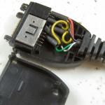 The two devices both use the Palm “MultiConnector” and the same cables. Here’s a doc with pinouts. The serial is 3.3V TTL. Of the various cables I have for the two, only one has physical pins in positions 10,11 where the serial is. I took it apart, and found those pins were not connected. (It only had USB wires Gnd, +5, Data+, and Data-.) But there are enough wires, so I should be able to move some.
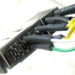
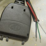 Done! The range of small pins (L to R from the back) is 17-5. White and green are now on 11 and 10. The original black – via one of the yellows – goes to 8, so I’ve got ground. After it’s all done it looks a lot like it did before I started. But now white and green ring out to the RX, TX pins :).
The Tiny Debug Serial package included with current tiny 45/85 Arduino cores is almost a drop-in for the normal Serial stuff, automagically figuring out if the target chip has no UART and slipping itself in. The package is send-only, but that’s really all I need. Just added a Serial.begin(9600) and some Serial.print()s, just like normal. I added a startup message and print the value read from the ADC once/sec. The analog in pin is currently hooked to a pot for testing.
I found an old Palm Hotsync manager and reminded myself how to install stuff on Palms. Found, downloaded and 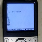 installed (free) ptelnet-0.61.prc to the Centro. Got it running on the serial port at 9600 and hooked Gnd/RX of the new cable to PB3 (pin 2) on the Tiny. Since the Centro is 3V logic, I used a 3.3K/10K voltage divider from the Tiny pin to protect it from the 5V logic levels.
And it works! I’m just using the built-in 8MHz oscillator divided by 8 for a 1MHz clock. Seems to be accurate and stable enough to run at 9600. Woo hoo!
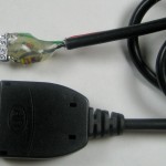 Now that it actually works, I terminated the cable for convenient use with a breadboard. It’s even labeled for TX and 3 and 5 volt RX. Hmm, seems to need a pullup to work. I don’t understand that, but it works.
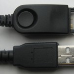
 Update 8/30/11: I have another Palm, so I’d like another cable. The hot sync cables lying around have the wrong pins populated. They needed USB, not serial, and so populated positions 5-8 and 12. Let’s see if I can move some.
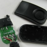 I opened up the connector and found a little PCB to hold the switch – no surprise there. But the pins seem to be soldered to both s
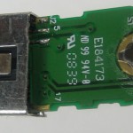 ides of the board. How’d they do that? And how did they get spring-loaded pins in there in the first place?
After meeting the challenge of unsoldering the board without doing too much damage to the pins (though the plastic suffered a little) I gingerly pulled a couple of pins out. That answered 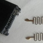 both questions: Clever manufacturing provided the spring. And the pins are reversible, with the solderable finger offset from center by about half a board thickness. The good news is that I can just pull them out and relocate them to the positions I needed. The other good news is that I can take advantage of the pin offset to give myself a little more working room on the two adjacent positions (10,11) I need pins for.
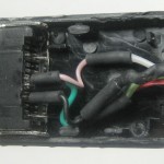 Of course the existing wires (molded into the strain relief) were too short, so I had to extend them before I could connect to the moved pins. And let’s hear it for heat-shrink!
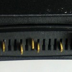 I only needed 3 pins (Gnd, TX, RX; 8,10,11) but I put the extra pins back in so I’d have them if I needed to disassemble it again.
A quick test and it works! Haven’t terminated the other end yet.
Update 1/19/12: The goal of this project was a cheap, simple way to get serial debug info at TTL levels from a micro on a breadboard. I’m now using another approach that mostly works better for me.
While the Palm is cool and portable, it has a couple of drawbacks:
* The connector is flaky. I have to keep pushing it in to make sure it works. I think what I did is OK, it just doesn’t snap very securely into the Palm.
* The terminal emulation I’m using responds to BREAK (line not held high) with an error popup and stops. I have to clear the error and then click the tiny On button to go online. Power cycling the micro produces a BREAK condition – and it’s a hassle. Another terminal emulation would probably work more gracefully, but I never got around to finding one.
* Since it’s battery powered, I feel like I have to turn it off all the time except when I’m actually looking at it.
My PC has several real RS-232 ports, so if I had a TTL to RS-232 converter, I could just run a terminal emulation in its own window and overcome all the problems with the Palm. Not very portable, but I’m in front of the PC most of the time anyway. Yeah, I could make something with 1488s/1489s or a MAX232, but there’s still the issues of power and 3.3 and 5V devices.
 Taking advantage of the fact that most RS-232 implementations don’t actually require negative voltages on input, I used this cheap and cheerful approach:
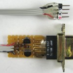 It wasn’t even worth making a PCB. Each side provides its own appropriate positive voltage. The RS-232 end (PC) must assert DTR true to get a positive voltage source, and by connecting the TTL side to local power on the breadboard – 5 or 3.3V, it works happily with either. And no external power required!
I’m still happy to have my Palm and cable as a backup, but this is now my main serial TTL tool.

Oh man, Jim… this would have been fantastic when trying to debug the attiny85’s for my blind closer. I was in the same boat, had it all wired to the Uno for ISP and figured it would be too aggravating to keep reprogramming the uno!
I really like your blog.. vry nice colors
& theme. Did you design this website yourself or did
you hirre someone to do it for you? Plz reply as I’m looking to design my own blog
and woud like to knnow where u got this from.
thanks a lot
There are no colors. The theme is WordPress standard “Twenty Ten”. There is no design. I just used straight out-of-the-box WordPress.