(Post rebuilt – see footnote.)
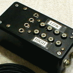
I’ve built several preamp/AGC/limiter boxes for square dance recording, each getting a little better than the last. (Well, the black one wasn’t so great.) I still aspire to a “perfect” device, answering all my needs. We’re getting closer now.
I need this device (maybe without single battery) for a couple of other recordists I’ve promised it to, so there’s some pressure to get it done.
Requirements/History
The ideal device would –
Just work. With one level set, NEVER distort or fail to record.
Be as simple as possible (but no simpler)
Not require AC power to reduce hum, provide quicker/easier setup
Accept any level from mic to speaker
Provide visual indication for setting the level
Have pigtails for input/output to reduce number of connectors
Create a new file for each tip, not recording the “silence” between tips
Have enough storage to handle at least a whole day, preferably a whole weekend
Have enough battery to handle at least a day, better a weekend
Have a battery test function
Be unlikely to accidentally turn on in it’s carry case.
Between “simple” and enough battery and storage, be an appliance I could hand to someone going to a weekend to bring back problem-free recordings. I’d be happy to write doc to support that use.
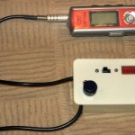 My best current device – the white one – is simple and reliable. The power switch at the end of the level control has a fairly stiff detent and along with a small diameter knob rarely turns on accidentally. Its 9V battery will run it for a couple of weekends, but the battery test indicator is a mechanical switch. The battery in the recorder is separate, and not reliably enough for one day. The 256 MB recorders I’ve been using aren’t enough for a whole day. It would still take a geek to operate it at a weekend. Still lots of room for improvement.
Several years ago I found a great chip – the Analog Devices SSM2165. Designed as a mic preamp, it has programmable AGC, and desperation limiting at the top end to avoid clipping. To avoid the problem of huge gain amplifying background noise when there’s no program material, it also has a noise gate. That implements a threshold below which input is attenuated rather than amplified. The effect is that with input below that threshold, the output is essentially silent.
They discontinued that great chip, with the tiny 0.5mm pitch SSM2167 as the replacement. I finally figured out how to solder that, discovered that it clips (!?!) on large peaks, sidestepped the clipping by hacking some more headroom in by reducing signal level between sections of the chip and not running it on 3V. Fought battles with recorders and have settled on the Iriver 800 series. They seem to have a little better battery life than the 700s, and might last a day on one AA. The 512MB models will handle a whole day unless we run into the “hum/noise problem”. The only shortcoming is that they don’t timestamp the files they create. That would be nice, but its absence is not a showstopper. There’s the possibility of trying to add more memory to these guys, but that’s a whole nother project.
Battery issues
The current separate preamp and recorder setup requires two batteries. If either fails the system fails. Ideal would be a single (big honking) battery that I can make as big as I need. Unfortunately, the recorders need 1.5V (a AA) and the preamp needs at least 5V. I could use a 5-6V battery and a regulator to get the 1.5V for the recorder, but that’s not very 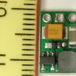 efficient. I found a tiny DC step-up device at Pololu that will take 1V or more and put out regulated 5V. While it is not 100% efficient, I think the preamp is the lower power draw, so that should work, letting the main battery be 1.5V. To power the recorder from that battery I’ll need a fake AA with a pigtail to put in the recorder.
 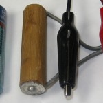 And since it’s not designed for external power, I have to somehow tie the recorder down so the fake AA doesn’t fall or get yanked out. I think I can do something cool with Shapelock to make a snap-in holder. But now I can put in enough AAs (or Cs!) to last as long as I like and still have good 5V for the preamp. So that’s the plan for the new version.
The larger problem is a battery level meter. The obvious way to display it is on the 10 segment display from the 3914. In early versions I used a DPDT switch to switch both the signal (AGC or battery) and some of the range/offset voltages going to the 3914. After some problems with reliability of the small slide switches I used, I’d like to avoid using them. Ideal would be a momentary SPST. CMOS analog switches should allow switching as many things as needed.
But the real problem is getting a linear indication of battery capacity remaining with the NiMH cells I most always use. The (unproven) plan is to put in a low power micro with A/D input and D/A output to read the battery voltage, do a table lookup, and put out a voltage to drive the 3914. I think I can do it with an ATTiny85. It has a 10 bit ADC in and 255 step PWM out. The single momentary battery test mode SPST would provide power to the Tiny and somehow control the CMOS switch. Since the discharge curve of alkaline and NiMH cells is very different, it would probably need a jumper or something to set which battery chemistry was being used.
To get the best resolution in, I’d like an analog reference around 1.6V. I could use a resistor and zener (powered by the battery test SPST button), but it’s extra parts. The Tiny has an internal 2.56V reference. The battery voltage range of interest is maybe 0.95 – 1.5V, which would come out with ADC values from 380 to 600. Tossing the low bit, that still gives me 110 values for the range of interest. Not ideal, but it should work. For 2 more resistors, I could divide the battery voltage down so it would fit with the other internal reference of 1.1V. But that would draw constant current. Hmm – what if the battery test button switched ground to the Tiny instead of power? No, the Tiny would have +5 at the top and +1.5 – through the divider – at the bottom. That would probably be enough to power it, which we don’t want. Maybe the 2.56V ref is good enough.
On the output side, I should be able to create a (noisy, PWM-based) voltage from 0-5V in 255 steps. When the 3914 is tuned for the AGC voltages of interest, the range is roughly 0.38-0.68V. (Well, that was the range with the 2165. I expect the 2167 is similar enough for the ballpark calculations here.) If I scale the 5V max PWM output down to 0.68V, the range from 0.38 to 0.68V is PWM counts of ~137-255. That’s ~118 values. If I throw out one bit, I’ve still got 59 steps. Since the 3914 lights one of 10 LEDs, I’ve still got ~6x the resolution of that device. Works on paper – wonder if I can make it work in real life? The fact that I can tweak the lookup table arbitrarily is encouraging.
Update 9/16/11: If I end up using that sweet Sansa recorder, things change a little. That runs off a little 3.7V Li-Po. The one that’s in it is 290mA-hr. I found some up to 5000 mA-hr that should let me use the original approach. The little DC booster will accept the 3.7V in. If the Sansa will run down to maybe 3V, I could use 3 NiMH in series. More investigation needed.
The battery indicator in the Sansa is calibrated for a Li-Po battery. If I use one of those, maybe I can just skip putting a battery level indicator in the preamp completely! The indicator is visible while recording, so it could be checked at any time.
But that doesn’t change the issue for using the preamp with non-Sansa recorders (of which I still have several!). And there are still two flavors of those: Stand-alone preamps for others (Les, Ron) that will probably have 6V batteries; and one for my 1.5V Irivers with 1.5V batteries. So there are really three versions of this preamp. No wonder it feels like I’m stalled on it!
The “hum/noise problem”
I can control the size of the battery, and buy recorders with enough storage to do whatever I need. And while it does require one manual level setting, if noted that setting should work for the whole weekend. The noise gate in the 2167 usually cuts the output during quiet times to low enough that the recorder reliably stops recording and waits for signal again.
But there’s one problem case I can’t work around (without a really major redesign of the system). If for some reason there’s a low level of background hum or noise, it may be low enough to not be a problem for the dancers – and in fact inaudible between tips unless you put your ear up to the speaker. But it can still be high enough to not be below the 2167 noise gate threshold, and thus be amplified enough to keep the recorder from shutting off between tips. In addition to adding a post-processing step of cutting the huge resulting file into tips, the recorder stays on, wasting both battery and storage. I can try to set the level a little lower and play brinksmanship to get the noise below the threshold without compromising the soft parts of the desired recording, but that’s a dangerous game.
I can overcome the battery issue (batteries are cheap), but storage is a problem. The ratio of active dancing to overall time is maybe 60%, so it results in almost twice the storage usage. But that’s not the biggest problem: I’d like to be able to not have to touch the setup between sessions. And if the hum remains on the few-hour breaks between sessions, the storage requirements go up very significantly. Now in practice the callers’ amp is probably turned off between sessions, so that worst case may be rare. But if I’ve given the setup to someone else to record a weekend I can’t attend, I could lose a significant amount of dance recording to this. If I cut the recording bitrate by a factor of 2 or 3, I could probably get by. And the lower bitrate recordings would still be usable – and infinitely better than no recording because it ran out of storage. But then I’m throwing quality away to hedge against an unlikely case. Ugh.
The Plan
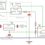 Here’s the current high level design. Single battery, micro for battery level, momentary SPST for battery test.
The main subsystems are the audio processing, power supplies, battery test, and the display.
The audio path consists of the input attenuator and 2167. I might add a little MCP6282 rail-rail opamp to give a little more output, making up for the signal loss in the headroom hack. Power to that chip(s) is through a main physical power switch, not shown.
Power is from an extensible battery of 1.2 V NiMH (or alkaline) cells in parallel. Their output directly powers the recorder through its fake AA cell. They also power the little DC step up board to get 5V for the 2167. I’d prefer 5.5V for a little more headroom, but the step up board I’m using isn’t adjustable.
Battery test mode is enabled with the SPST button. That powers the Tiny85 and flips a CMOS switch to route the filtered DC from the PWM output to the 3914. I may have to play with logic levels (maybe a pulldown) so the CMOS switch defaults to the channel with the 2167 AGC voltage. One remaining concern is whether putting 1.5V on an input pin of an unpowered Tiny will damage it. Needs to be checked out. If that’s a problem, I’ll need to dig into sleep states or something to keep the Tiny from eating much battery.
Not shown for the 3914 is a small network of resistors/pots to set the high and low ends of the range to match the 2167. May require manual calibration – or maybe just 1% resistors if I make a bunch of them. Those resistors also set the LED current.
I haven’t breadboarded the battery test stuff yet. It should work, but I hope I have enough sense to test it out first. Oops – I don’t have any DIP LM3914s. That’ll put testing off a bit.
Update 9/20/11: OK, I’ve gotten the analog in and PWM/DAC output pretty much working with the Tiny85. There’s a sleep/wake I haven’t tried yet, but it should work.
Next step is finishing the board layout. I don’t have any SOIC Tiny85s, so the first board will use a DIP. Maybe with leads flattened and surface mounted to minimize layout change for the SOIC.
Possible major redesign
This isn’t any more than a thought at this time. Currently the user (potentially not me if I ask someone to record a weekend I can’t make) requires separately turning on the preamp, turning on the recorder and putting it in record mode. I could reduce the user interface to a single on/off switch and a level set if I embedded the recorder into the device along with a microcontroller that could operate the recorder. I found some cheap 1GB recorders (~$16) that I disassembled and started to investigate spoofing button presses on, but didn’t get too far. If I could do that, and if I put in my own signal processing to determine when to start/stop recording, I could implement a smarter noise gate that would figure out there was hum/noise and change its threshold to turn off recording between tips despite the noise. Lots of work. Maybe some day. Maybe.
Recorders
(Section started 9/3/11.) While not directly about the recording preamp, I’ll try to collect here my thoughts and recollections about various recorder hardware I’ve used with the recording preamps. For reference, the application is recording live square dances with the intent of producing very high quality recordings to play back for basement or “tape group” private dancing.
Connection is direct to the caller’s audio system, with typically line-level audio either from the amplifier (usually Hilton) or from a “patch box” in line with the speaker cable, electrically in parallel with the speaker. Program material is mono. While near studio quality, these recordings are never sold – including by the caller – or used for public dances where money changes hands.
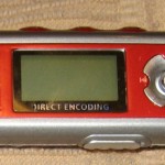 The first hardware MP3 recorder I used for square dance recording was an Iriver IFP-790. It has 256MB of flash and a line-in (or mic-in) jack. Audio quality is very good, and that has earned IFPs a reputation of excellent sound. They will record in mono (or stereo), doubling the recording time. They have an auto start/stop mechanism that starts new recording files with each tip, skipping the silent time between tips – exactly what I need. This recorder is red. Others in the family are the 795, a silver 512MB model; and the 799, a 1GB model (sorry, never had one and don’t know the color). I’ve gotten all my Iriver recorders used on Ebay. Appropriately, prices run higher for models with more memory. I’ve been paying $35-40 for 256MB recorders (790/890).
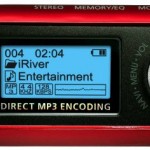 An updated Iriver family is the 800 series, with a red 256 MB 890, a silver 512MB 895, and a 1GB 899. The 800 cases are a little larger, more rounded, and have some connectors moved around. Functionality is just about the same, but I think battery life while recording is a little better. Both 700 and 800 series use a single AA cell – primary or NiMH. Most of both families also have an FM radio built in, though that provides no value for my uses. A significant drawback to both 700s and 800s is that there is no record level indicator in the user interface. It is that shortcoming (along with lack of AGC on line-in recording) that has forced me to design the recording preamp this note is about.
There are 2 major families of firmware for these 700 and 800-series recorders. The original would only connect the the Iriver Music Manager software running on a PC (don’t know about MAC/Linux). The other, called MSC makes the recorder look like a USB thumb drive. A limitation of the USB drive versions is that the highest MP3 bit rate it will record is 96Kb/sec, and opposed to 128 (or 160??)Kb/sec for the Music Manager version. Both are at 44KHz sample rates. Lower sample rates and bit rates are also supported. After some moderate experimentation years ago, I found I couldn’t hear any difference above 160Kb/sec for stereo recordings (though 160 was better than 128), and so have standardized on 160 for my home stereo MP3 library. That’s like 80Kb/sec for mono. While I’d record at 128Kb/sec if I could, 96 still gives me a little quality headroom so when I resave at my standard 80Kb/sec after normalizing volume and doing some minor editing I probably haven’t lost much fidelity.
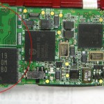 At least the 800 series devices have places on the board for 2 memory chips. I’ve looked pretty hard for the Samsung chips they use, but have never found any way to buy them. There are 256 and 512MB versions of the chip. I have a dead 790 (power supply burned up while trying to measure current draw using a bench supply – ouch) and I’d like to try putting its memory chip into another device to see if it would recognize it and give me 512MB. The SMT rework would be a challenge, but I think I can do it. I’ve bid on dead 512MB devices, hoping to scavenge the memory and build up a 1GB device, but never won any. I haven’t actually moved any chips yet.
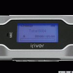 Another Iriver model I’ve tried is the T30. I’ve had a red 256MB and a silver 512MB version. This runs on a single AAA cell, limiting its recording duration in my set-it-and-forget-it application. It also will auto start/stop recording, but records in stereo only, essentially cutting record time in half for a given memory size (read: cost!). I also have had some problems with auto start/stop reliability on this model, though that might be my fault. On the plus side, these recorders (maybe only with Music Manager firmware?) put time stamps on the recorded files. I wish the 700/800s did that! In any event, that’s enough strikes that I don’t bother with T30s any more. I haven’t sold the ones I have yet, but I should/will.
I think I tried another lower model – maybe IFP 300 series? – but it didn’t have enough features (no auto start/stop? no mono?) to be considered.
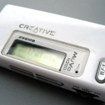 I also played with a little Creative Muvo N200. It uses a AAA, and didn’t work well for my application. Maybe no auto start/stop? Anyway, it was kind of a non-starter.
I also found a non-name brand 1GB recorder I could get for ~$16. It had limitations, too, but for the price was considered for hacking into an embedded recorder. I took it apart with the goal of hooking wires to the critical buttons on the user interface, but never got very far.
I ran into a guy recording at a couple of weekends using Sansa recorders. He had hacked into the recorders to put in a line-in jack from where the internal mic was connected. He was running the open source RockBox firmware, which provides excellent and flexible access to most everything the recorder is capable of – usually much more than the manufacturer’s firmware provides. He had built them into Altoids boxes, and had a couple made up for recording in multiple halls at large dance weekends.
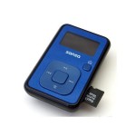 I just ran across a 4GB Sansa Clip+ on Woot for ~$20. I checked, and RockBox is well supported on that device. It will require a hardware hack to get a line-in jack, but if it works well it will completely resolve the issue of recording storage in the face of the hum/noise problem with just the internal 4GB. And it supports a micro SDHC in addition! Battery is 3.7V (LiPO I expect) and not intended to be replaceable. I ordered two of them, and will report more as I learn about them. I do have high, if slightly guarded hopes. Wow – open source – I wonder if I could use RockBox to embed a recorder and control it semi-remotely?
LM3914 Programming Resistors
To avoid having to look up / figure out this nonsense every time I do a new board, let me put it all down here for reference. For example values, I’ll use the typical 3mA LED current and a range of 0.3 – 0.68V, about what we see on the 2165′s AGC averaging capacitor.
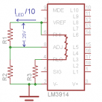 We use the magic reference source to set the voltage at the top of the dividers that set the range (Rhi). Details of that follow, but assume we have our 0.68V at Rhi. The internal divider chain is 10 x 1K. We need the bottom of that chain to be at 0.3V, so R3/(10K+R3)=0.3V/0.68V. That gives about 7.9K for R3. Since we’ll need it later, there will be 0.68V/17.9K=0.038mA thru the chain. Note: pic at right is wrong. RHI goes to ADJ, not VREF.
Each LED will be provided with 10 times the current out of VREF (Ref Out). Since we want 3mA LED current, we want 0.3mA out of Ref Out. That current must all go thru R1. Since the magic reference always provides 1.25V between Ref Out and Ref Adj (ADJ), we’ll have 1.25V across R1. Its value then must be 4.17K. Ugh. How about 4.7K? That would give 2.65mA for the LEDs. Should be good enough for a first pass.
Now the magic reference source adjusts the voltage on Ref Out as needed so about no current flows in/out of the Ref Adj pin. That design characteristic of the reference source means whatever current flows through R1 must also flow thru R2 (well, and the internal divider chain). The voltage across R2 is the 0.68V we need on Rhi, so R2 would be 0.68V/0.265mA=2.57K.
But unsimplifying, the current in/out of Ref Adj isn’t exactly zero: That pin sources a fairly constant 0.12mA. So we have 0.265+0.12=0.385mA flowing thru R2 and the divider. We saw above that the divider sucks up 0.038mA, so the actual current thru R2 is 0.385-0.038mA, or 0.347mA. So the real design value of R2 is 0.68V/0.347mA=1.96K.
To allow for a little tuning (like if the 0.3 – 0.68V range isn’t quite right) we’d like to be able to adjust the voltages at the top and bottom of the internal divider independently. Adjusting the bottom is easy: make R3 variable. A 10K pot should be ideal. And since the current thru the divider is fairly small compared to our 0.3mA of LED programming current, small changes due to tweaking that 10K can probably safely be ignored.
To adjust the voltage at Rhi, we could make R1 adjustable, R2 adjustable, or put a pot between R1 and R2 with Rhi/Ref Adj on the slider. Adjusting R1 directly also changes the LED current, and while that’s not critical, that’s not ideal. Making R2 variable changes only the voltage at Rhi/Ref Out – ideal. (Well, and small proportional change to Rlo.) And if we make it 5K, we’re about mid-range – great!
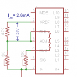 I did a quick test, and this probably “final design” works:
And now I should never have to think thru it all again!
(Later) While all the logic and math above is correct, the initial assumption that the 2167 and 2165 voltages would be about the same was not. Appropriate voltages for the 2167 are ~0.55v – 0.82V.
Update 6/5/12: For the record, here are the final resistor values (shooting for ~0.82V and 0.55V). I don’t want to have to tune pots in each copy of the preamp I make, so I’ll use fixed values. For the LED current determining resistor between pins 7 and 8, 4.7K works fine.
To determine the RHi voltage, I laid out 2 resistors in series between pins 6/8 and ground. Target value was 2.7K. I don’t have any of those, but 1K plus 1.5K seems to work OK. I got ~0.795V in the instance I checked. For RLo, I laid out 2 resistors between pin 4 and ground. I think the design value was 24K; I ended up with a 22K plus a 2.2K. At the low end of the scale if the bottom LED is lit, we’re just slightly above the noise gate. I think if I get some 2.7Ks, it will move both voltages up just a smidge, slightly improving the tuning.
First version: for Sansa Clip+
(Updated 10/20/11) Time is getting really short to get this done before the next square dance weekend (Heartland, in a week). I’ve narrowed my sights to just making a couple of boards specifically for the little Sansa recorders.
To use a single battery for the electronics and the Sansa, I removed the battery from the Sansa. (More details in the Sansa Hack post.) I only need 3 connections out of the Sansa: Ground, V+, and Audio In. Removing the battery gives me a place to mount a little PCB with 3 normal 0.025″ square pins sticking out the bottom of the unit. The pins are on 0.1″ centers, but skipping 2 pins between each, giving 0.6″ between the outside pins. These pins will be a primary part of the physical mounting, so having them farther apart provides a more secure mount. I have some old wire wrap sockets which when cut in half and mounted sideways should hold the Sansa just enough off the board to clear the components beneath. Some hot melt at the opposite end will complete the Sansa’s semipermanent attachment to the PCB.
Housing will be an Altoids tin – with a little window in the top to see the LEDs and the Sansa display. There’s enough room for everything, but to get to the USB connector on the Sansa I’ll have to kind of lift it out of the box. Current plan is to make some kind of semi-official hinge at the end of the PCB. I’ll need to pay some attention to the thin coax audio input cable so the flexing of raising the board on its hinge won’t cause problems.
The board is finally done – still sort of a prototype. There’s a programming header to tweak the firmware on the Tiny85, and the Tiny itself is an old school DIP with pins folded under to surface mount it. The whole assembly is still quite thick.
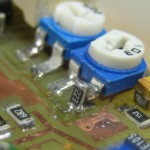 (later) Board is now assembled and tested. The bad news is that the max/min averaging cap voltages I need the 3914 to cover aren’t the same as what I had recorded for the old 2165 chip. Instead of 0.33-0.68V, it’s on the noise gate threshold at ~0.55V, and the front end (not the VCA) starts to clip (with music) at ~0.82V. I can’t hit the 0.55V with the 5K pot on the board. I unsoldered one end, bent it up, and fitted a 22K 1206 resistor on end between the pot leg and the board. Really ugly, but now I can set the 3914 to the voltage range I need. And now the whole thing works! The other bad news is that it’s too tall to fit in the Altoids tin. Off to the Container Store.
Wow – they have a lot of good candidates for project boxes there! I found some that were considerably larger than I want or need, but will suffice for the rapidly approaching weekend. The good news is that with the generous box I won’t need the extra complexity of hinging the PCB. I can get to the Sansa’s USB connector with it glued flat in the box, and I can still get to the power switch on the top of the Sansa. One down, one to go!
But first, the board needs to have a nice home for that 22K resistor. And let’s try some SMT LEDs instead of the big clunker bar display. And since some of the caps weren’t the size I thought and were a hassle to solder in, let’s change the board for the correct SMT packages. And as long as I was in there, I moved several components around a little to make the traces less convoluted. With the updated artwork, I made the second board.
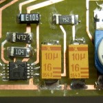 But when I first fired the board up, it wouldn’t record. The LEDs danced appropriately to show signal was coming in – but nothing was going out to the recorder. With that info, I soon found I’d made a boo-boo on the board: Of 2 big caps right next to each other, one had one end grounded, the other didn’t. But as I moved them around and updated package sizes, I incorrectly slid the second one so it was also on a ground trace. Fortunately, cutting the trace on both sides of the cap fixed it, and with further good fortune both sides of the trace were connected elsewhere, so I didn’t even have to jump around it.
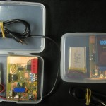 With that hack the second preamp worked, too. Here they are. I took the recorder out of the first one so you can see what’s under it. The little brighter green PCB just abouve the blue Sansa socket is the Pololu 5V DC-DC converter. The 3914 is obviously next to the LEDs; the quad CMOS switch is at the top; the Tiny85 8 pin DIP is next to its programming header; and the real brains of the outfit, the 2167, is the tiny chip next to the cap I had to cut traces around. The (green) SMT LEDs are a lot smaller than the red block on the first one, but don’t really let me make the board much smaller. Unfortunately, both LED arrays feel upside down: Highest volume is the LED at the bottom. Boo.
While the cases are twice as wide as I need, I really like the fact that the box protects all the controls when the top is closed. I’ll keep that feature somehow in the final version.
Here are all the recording config options I think matter:
Format: MP3 Bitrate: 96K Freq: 44.1KHz Source: mic Channels: mono
Prerecord time: 3 s Trigger: repeat Trigtype: stop
Start above -27dB for 0 s Stop below -32dB for 15 s Presplit gap: 15 s
Peak meter release: 1 u hold: 500ms Log scale, -50 to -6 dB
General settings->System->Start screen: recording
Recording screen->Gain: -3dB
Update after the weekend: The preamp/recorder combos both worked flawlessly. I started them before the first session in the morning and collected them after the last session each day. No more running around like a crazy person to collect or at least turn them off between sessions. Hooray!
Well, almost flawless. The average recorded level was ~-31dB, maybe 10dB lower than I’d like. Yeah, I can normalize it back up, but it’s an extra step, and I’d like the recorder to get it right in the first place. Unfortunately, if I increase the Recording->Gain (not Volume – that’s playback output) even to 0 dB, it clips on peaks. Hmm – it’s open source. I wonder if I can make a private version that gives exactly the level I want?
Update 6/5/12: This post was rebuilt from an old backup I was very lucky to find. The whole post had somehow been deleted. It used to be page 1611. There are some details here.

