SD amp fix/upgrade

The amp on the portable speaker I’ve been using for years for basement square dancing felt exceptionally hot after a dance recently.  Sound was still fine, but even after sitting for a few minutes with no audio input, the fan was blowing dangerously hot air.

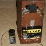
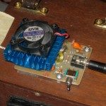
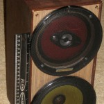
Originally designed to run off 12V for a square dance float for a local parade, the amp is a 2x20W TDA 8563 with a little heatsink and a fan on a home made PCB, mounted on top of an old speaker enclosure hacked to (barely) hold two big ugly speakers.  (The speakers were originally both coax, but I pulled the tweeter on one because it sounded too harsh overall.  Each channel of the amp drives one speaker.)  It’s OK on 12V, but it’s better with a couple more volts.  I got a little 4V gel battery and wired connectors to hook it in series with the 12V that lives on the speaker when I needed a little more volume.  But since most of its use is comfortably indoors, I found a 16.5V laptop supply and use that most of the time.

When I got it home I poked a thermocouple junction into a corner between the amp IC and the heat sink.  Running with the AC supply and cranking it up, I watched the temp hit 230F after a few minutes.  That’s about the absolute max temp, so it’s pretty bad.  A little playing showed that if it ever got above around 120F, it would fairly quickly hit 230, regardless of whether there was any audio input.  Thermal runaway!  That must have been what I saw (felt) at the last dance.  If I ran from a 12V battery (at 12.6V) thermal runaway didn’t occur.  Hmm – I really want the greater volume a higher supply voltage gives, but I can’t let it get that hot.  What to do?

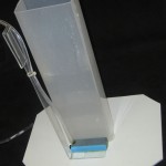
I found a pretty blue heatsink in the junk box that provided maybe 3 times the surface area and could be made to fit.  But as I was taking the old one off, I noticed it was loose – providing poor thermal contact.  Was that the problem?  I’m quite sure it never used to get that hot.

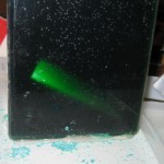
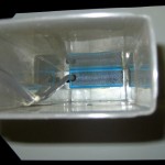
Since I mostly wanted a working system, I went ahead and mounted the bigger heat sink.  I did make sure it was bolted down nice and tight this time 🙂  You can see the thermocouple probe on the left.

But the higher voltage supply still spooked me a little.  Abs max voltage is 18V, so the 16.5 should be fine, but I could afford to cool it down a little.  I made up a little M-F extension to go in series with the AC supply with two several-amp rectifier diodes in series.  Let’s see – 1.6V at maybe an amp is a watt or two.  I’ll expect them to get fairly warm, but they should handle that no problem.  They dropped the 16.5V to 14.9 under load, and I felt better.  Test time.

To my delight and amazement, I could crank the newly-heatsinked amp up to full (undistorted) volume and even with the AC supply and without the little diode voltage dropper, I could never get it above about 95F!  I still don’t know how much the better heat sink contributes, and how much getting rid of the bad thermal connection helps, but I’ll take it.

While that little speaker/amp has been a real workhorse and has never failed, since I’d had it all apart, I did bring a spare setup to the next dance.  (The spare was not needed.)  I kept a close eye (well, finger) on the new heatsink, but it never got more than a little warm.  Success!

Posted in Miscellaneous | Leave a comment

Free invisible clips (and more Christmas LED repair)

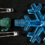
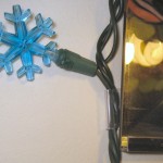
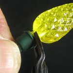
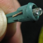
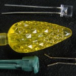
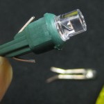
Another (now pretty routine) LED Christmas light repair.  The pretty blue snowflake LEDs that live around the living room mirror were dead.  I took the string down, pulled the bulbs, tested each (with the LED tester on the front edge of the bench) ’til I found the bad one, replaced the LED and it’s done.  It was the usual 3mm LED and a diffuser that snaps into the socket.  The LED fits up inside a hole in the middle of the diffuser.

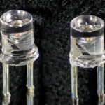
The only mildly interesting bit was that the 3mm blue LEDs I had have a sort of collar around the bottom.  I had to hack that off with some flush cutters in order for it to fit up into the diffuser.  Quick and painless.

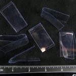
Much more interesting was being reminded (as I took the string down) of the clips I used to put the lights around the mirror.  I cut some strips of the very nice clear plastic used in all those annoying clamshell packages.  (I can barely stand to throw the stuff away, and have a nice stash for just such occasions.)  Bending a loop of it to fit around the wire and slipping the rest behind the mirror (or into the window frame or where ever) provides a fairly secure, almost invisible mounting clip.  It’s easy to tweak for fatter or skinnier openings, and it’s free!  (Well, assuming that you keep a stash on hand.  You do keep your old clamshell packaging, don’t you?)

Posted in Invisible clips | 1 Comment

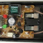
Cheap USB charger

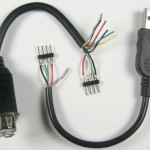
A small wall wart USB charger I was counting on failed to charge my phone, looping in a charge-for-half-a-second/won’t-charge cycle.  When I got home and started to investigate, I was stymied by lack of a way to get my hands on the wires in the USB cable.  That had happened before, so I bit the bullet, cut up some cables and terminated the ends with nice friendly 0.1″ header pins.  Fine – back to the problem at hand.

Patching the USB cable halves together with a little breadboard and plugging the phone in to charge, I watched the voltage as the will-charge/won’t-charge loop played.  The voltage dropped to 4V or so while it was trying to charge.  OK, it’s pretty clear – the charger can’t supply what’s being asked of it.  So replace it.  I scrounged up a higher capacity wall wart USB charger, and my charging needs were met.

But that charger was to live in the car, and that left me with no highish capacity wall wart in the box/as a spare.  Ebay served me well (I thought!) and I ordered a 300mA charger (from China, of course) – for $0.99 with free shipping.  (How do they do that?)

Oops – what arrived was a duplicate of the one that didn’t work.  A quick load test (facilitated by my new breakout cables!) confirmed the problem: though rated at 300mA (+/-30mA) it would barely do 200.  Since it was spec’d at 110-240VAC, I tried it at 136V – the most my bench variac would put out.  It did moderately better.  At 240V, it might even have hit the 270 mA spec.

OK – two next steps.  One, write back to the vendor, asking that he supply a charger that actually at least met the spec he advertised, or I’d have to provide negative Ebay feedback.  That’s apparently a pretty big club.  Yeah, for 99 cents it’s a great little 200mA charger.  But that’s not what it said, and that’s not what I needed.

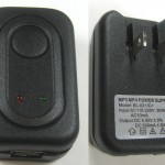
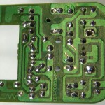
Second, can I goose it up to better output on 120VAC?  What I see:  There are 2 LEDs – red for power and a green apparently for “charging”, starting to light around 100mA and getting brighter with more current.  At higher currents, the red one dims.   There is a zener, no visible 7805, 2 transistors, some diodes, a full wave bridge, and a transformer with 6 leads.  Is it really a little switcher?  The ripple on the output under enough load to drop the output voltage is 60Hz – not 120, and not the 50 or 100KHz I’d expect with a switcher.  There’s a diode in series with one of the AC leads – probably related to the 60 Hz ripple.

Guess I’ll need to reverse engineer a schematic out of it (more challenging with that 6-lead transformer, but at least it’s only a single sided board).  Ugh.  Is it worth it?  There’s a medium chance I can get the other 100mA out of it for swapping a couple of parts – though I don’t actually know if that’s enough for my phone.  If I just leave it open and postpone the decision, it’s yet another bit of crap on my bench.  Or I can call it a great cheap 200mA charger and put it back together.  Decisions, decisions.  I guess that’s how my bench gets so full of  crap.  Ugh.

2/7/21:  Interesting.  I happened to be casually looking at this old post, and while I haven’t reverse engineered a schematic, a new possibility occurred to me.  There’s what could easily be at least an attempt at an AC input/DC output physical distance separation across the PCB.  Two hypothetical ‘output’ terminals of the transformer are on the DC side, where the Zener, a potential filter cap, LEDs and the USB port live.  Looking back at original, higher res pics, that light-colored 4 pin device, which spans the HV/LV divide is marked ET1109, which is indeed an opto isolator.

So one possibility is that it is in fact a switcher, with the two transistors as the oscillator, and the opto providing feedback to the HV side.  Possibly the oscillator failed, and the poor transformer – designed for 100KHz or whatever – had crude half wave rectified AC rammed thru it, and sure enough, the DC side took what it got and put out what 5V current it could.

That’s all pure hot air, of course, but it’s interesting to look back later and see a possibility that I missed 9 years ago.

Posted in Miscellaneous | 2 Comments

HDR partial success

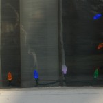
After I hacked some pink/purple LEDs into some Christmas light strings and wanted nice pictures, I faced the usual problems of photographing lit LEDs. The ones I wanted were from outdoors looking into a window at night, making it even a little more challenging.

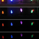
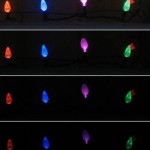
My first pictures wouldn’t even let me try to use picturenaut – even with manual -2EV exposure, the LEDs were overexposed.  I remembered that CHDK on my little Canon SD600 provided some bracketing, and soon figured out how to use that, including the counterintuitive option of “+” for brackets with decreasing exposure.

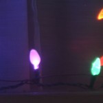
The first set of brackets (left) looked very promising – from bright enough to see the window frame and curtains inside to one with the LEDs underexposed.  At 2/3 EV per shot it covered a little over 9 EV, and CHKDK put EXIF info in the images so picturenaut knew what the exposure differences were.  But the software couldn’t work enough magic to make a great picture.  I tried several combinations of the source images and played with most of the adjustments in the four post-processing tabs, but in the best I could come up with the pink LED was still pretty washed out, with the highlights near full white – just what I wanted to avoid.  (right)

Lauren made the excellent suggestion of trying during daylight to decrease the contrast with the background.  That produced pretty promising pictures of the LEDs with plastic diffusers, but the hack with a white card for the pink LED to light up was way too well lit by the daylight and again washed out.

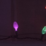
Later, in twilight, I tried using spot metering on the LED of interest.  That helped a little.  I did another set of bracketed exposures (again about 9 EV), and for reasons I don’t understand, picturenaut was able to do considerably better with those.  It gave me something about like what it looked like to my eye.  Sorry about poor focus – I didn’t notice it until I was back inside with the tripod taken down.  I did a +0.4EV brighten on what it produced for the picture on the right.

I guess the biggest takeaway is to remember that CHKDK will let me get the low exposures I need for HDR to have a chance.  Next is that magic spoils us (or at least me).  After seeing what picturenaut could do, I’m now disappointed when it can’t create a storybook picture out of chaos.  Or maybe I just didn’t play with the knobs enough 🙂

Posted in HDR | 1 Comment

New air stone for PCB etch tank

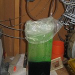
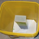
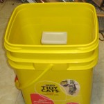
I’ve been using my new Container Store spaghetti-holder etching tank with cupric chloride etchant for several months now, and I’m pretty pleased with it.  I can walk away and let the bubbles do the etching, needing only a visit halfway thru to flip the board vertically for more uniform etching.  I glued a piece of plastic on the bottom so it won’t tip over.  The tank even has its own custom carrying case for going to show and tell.

A shortcoming has been the small air stone making the bubbles.  At an inch or so long, it doesn’t distribute the bubbles across the 3 inch width of the tank as well as I’d like.  I’ve had a longer stone for a while, and finally set up to use it.

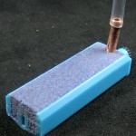
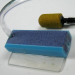
I cut the stone down to fit the width of the tank.  A hacksaw cut the stone and plastic very neatly.  The first limitation was that the air feed was straight into one end.  To keep the stone as wide as possible without kinking the air hose, I needed to feed air in from the top.  I found a bit of copper tubing that just fit the air hose and drilled a hole for it (the stone drills nicely).  Five minute epoxy has held up well in the etch bath (holding the board holder together), so I was going to epoxy the tube in and slather more epoxy on the cut end to seal that up.  But in a rare stroke of Murphy avoidance, just before I epoxied the tube in it occurred to me that copper probably wasn’t a very good material to use in a bath designed to dissolve copper.  So I drilled the hole out a little bigger to fit the vinyl air hose and epoxied that directly in.  Not ideal, but (better than using copper! and) worst case I have to re-epoxy it once a year.  Here’s the almost-final configuration, with the old (stained) air stone posing in the background.  I glued a little bit of plastic on the bottom to keep the stone over to one side of the tank.

When I put the new stone in the tank and turned on the air, it refused to sit politely on the bottom of the tank.  Something about being full or air, I suppose.  The tank was about due for some cleanup, so since I was going to have to fit some sort of hold-down into it, I dumped the etchant back into its original glass jar and cleaned up the tank.

I ended up epoxying a 3/4″ wide strip of acrylic to the new base of the stone and bending it to clip around the top of the tank.  That would hold the stone down well, and provided a good way to manage the air hose as well.  An extra benefit is that with the air hose coming out one corner, the plastic baggie I stuff into the top to contain the spray when it’s bubbling (etching or regenerating) seals much better than it did around a clamp I’d been using to hold the air hose in place.

For the tank and bubble system, I think this is about the final configuration.  I’m still thinking about better ways to hold boards in the tank.

Posted in Cupric Chloride Etchant, PCB Etching | 2 Comments

Hacking pink LEDs into Christmas lights

LED Christmas lights are cool.  Unfortunately, some older strings didn’t have the neat pink/purple LEDs.  We have some with with just red, green, blue, yellow, and orange.  The yellow and orange are quite close, and are the least exciting colors.

So I got 100 pink LEDs (from China) and started improving things.  One string just had normal lens-ended 5mm LEDs.  This makes for very non-uniform brightness, depending on viewing angle.  I suppose some might consider that an “interesting” feature.  To avoid the bright flash if you happen to view it on-axis, I chose (5mm) flat top LEDs – no lens.  Replacing some of the original yellow LEDs from that string was about like replacing regular incandescant bulbs in older strings except that to observe polarity, the sockets are asymmetric and one leg of the LED bulb is longer than the other.  (That picture had the LEDs powered from a Variac turned down considerably, along with some fill light.)  One string down.

The other target string, which is strung around the living room window, was more challenging.  Designed to look like traditional bulbs, these LEDs had bulb-shaped plastic diffusers.  That caused a couple of problems.  First, the bulb/diffusers were colored plastic.  My pink LEDs inside a yellow bulb weren’t going to look very good.

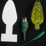
But after I levered the bulb off the bulb holder, I found the original LEDs were 3mm and fit down into the socket and up inside the “bulb”.  My 5mms would never fit, and couldn’t be significantly cut down in diameter.  Putting a new LED in was easy enough, although it sat on top of the bulb holder.  What do I do about a bulb?  Cheat.

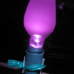
I cut out some card stock in the shape of the bulb, extending far enough down to be lashed to the socket.  The LED would illuminate it from the side.  I’d locate the card stock bulb on the inside, so it would present the best appearance for outside viewers.  To reduce the effect that the bottom was much more brightly lit than the top, I curved the top so light coming out of the flat LED top would hit it.

The fakes obviously don’t have the jewel-like facets of the originals, but to a casual observer walking by, they don’t look glaringly different (except for the pretty color).  Sometimes low tech is good enough!  The picture suffers from the perennial problem of photographing LEDs.  That one was underexposed by 2 stops – as far as I could make my camera go, so I couldn’t even get a good enough bracket set to try HDR on it.  Hmm – I wonder if I could get lower exposure with spot metering?

Anyway I’m pleased with the results.

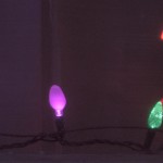
Update 12/19/11:  I tried spot metering and also got the camera to do some bracketing so I could use picturenaut HDR.  Not great, but better than the one above.  There’s a little more on the HDR side here.

On looking at the lights for a while, the pinks are very nice, but the yellow/orange are less so, so I added more pinks.  The original order was red orange blue yellow green.  I originally replaced every other yellow.  This time I replaced the other yellows.

I did actually try the pink LED with a yellow diffuser this time, and sure enough, it doesn’t look very good.  But at least now I’ve done the test.

Looking at the string, there seemed little difference between most of the oranges and yellows.  As I replaced more yellows, I started looking at the bare LEDs I removed.  They were orange!  Since the yellows were prettier than the oranges, I extended my replacement exercise by swapping in yellow tops (that I’d removed for pinks) for the orange tops.  Not great, but it helped a little.  If I’d had 3mm yellows, I might have replaced the orange LEDs.

The other good news is that one of the pretty blues was dead.  Fortunately, it failed by shorting out, so the rest of the string stayed on.  I happened to have some 3mm blues, and with a little fiddling replaced the bad one.  Looks fine.

Posted in Pink LED hack | Leave a comment

Luxeon Rebel LED

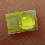
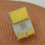
I got three of these 3 W Luxeon Rebel cool white LEDs from SparkFun as possible sources of the flash in the RF starter’s gun replacement project.  I’ll run them at close to the 1A absolute max current, for maybe 10 or 20 ms.  The big pad is just for heat sink.  Operating current is through the 2 small pads.

Making a holder for them was pretty pleasant.  While the Eagle footprint from SparkFun said “for any Luxeon LED”, it clearly wouldn’t work for these.  But there was a footprint in the led-lumiled library that looked good.  While the design current is very high, duration – and thus power dissipation – is low, so I didn’t worry much about heat sinking.  I did still provide some copper for that pad, though.

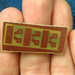
The PCB with 3 layouts of the mount was so small I could put it on an otherwise unusably small scrap of PCB material, and I’m still using my regenerable cupric chloride etchant, so they were essentially free.  I like that.

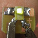
As expected, it’s very bright, and I haven’t even run it above 60 mA or so.  I haven’t put together a good current limited pulse supply yet, but it will be interesting to see what it does as a flash near 1A!  Here is it at about 0.1 mA.

There are two options for the optics.  It’s vaguely possible that it will just be aimed in the general direction of the runners.  From the datasheet, the half-power cone is ~120°, so aiming wouldn’t be very fussy.

The more likely arrangement would attempt a horizontally omnidirectional distribution, with a fairly narrow dispersion vertically.  All the targets of interest (runners, other officials, timing system optical sensors) would be within a few degrees vertically of the LED at the distances they would typically be from the flash.  Inspired by some landscaping lights I’ve seen consisting of a maybe 8″ diameter post in the ground, 4′ tall, with the top 8″ a clear cylinder housing an upward-shining light with a sort of conical reflector – point down, with a concave curved cross section (it’s hard to describe!) providing an omnidirectional downwash of light, my first attempt will be a small (~0.6″ diam?), short (~0.25″?) conical reflector possibly turned out of aluminum, well polished.  About the only science I can offer for the actual cross section will be hand sketched ray diagrams.  Looks like the point of the cone facing the LED should have an included angle around 90° so light originating vertically would be reflected straight out.  Should be interesting.

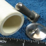
Update 12/5/11:  Posted a “how do I make this” question in the Workshop88 chat room for the reflector.  Got lots of interesting suggestions.  Was inspired to try stretching some thin aluminum sheet, and it worked out pretty well.  Using a bit of 3/4″ PVC pipe as a die and a bolt hand ground (not turned) to a ~90° point and the very point rounded a bit, I got a pretty reasonable shape.  I used a sharper pointed punch at the very end to do the very center.  A little metal polish and it looks about like what I think is needed.  Here’s a little clip of it.  The flat edge needs to be trimmed, and of course some sort of mounting provided with adjustable distance from the LED to “focus” it.  Watching the shape of the band of light (I hope to see)  on the wall in a darkened room as that adjustment is made will be interesting.

The reflector’s size makes it easily printable on the Makerbot.  I created a model in Sketchup, but haven’t taken it any closer to Gcode than that.  Of course the Makerbot’s resolution isn’t nearly good enough for a mirror finish, so either smoothing with acetone or filling with epoxy or plaster or Bondo or something and sanding smooth and polishing would be required.  Possible silvering methods include painting with conductive paint and electroplating it and painting with chrome spray paint.  I haven’t tried the latter, but the results on videos on YouTube look pretty good 🙂


Posted in Luxeon 3W LED | 3 Comments

Getting ATtiny4313 to work with Arduino IDE

I got hooked with how easy it was to get a Tiny85 running with the Arduino IDE:  Drop a directory of stuff (including core libs) in the “hardware” directory, hook a couple of wires up to an Arduino running ArduinoISP as a programmer, touch up the Blink sketch to use the 85’s pins, pick a new board that magically appeared under the Tools tab, upload – and it works!
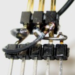
Those core libs already supported the Tiny2313, so how hard could it be to get the 4313 I need for a short-deadline project up and running?  (Even optimist that I am, I should be able to recognize famous last words by now.)  I kludged a little breadboard adapter so I could use(/test!) my 6-pin Arduino style ICSP programmer cable and stuffed that, a 4313, and some LEDs into a breadboard.  I found the pin definitions mapping Arduino style names (like “1” for digital pin 1) to logical hardware ports (like PD1) and to physical pins on the 2313 in \users\jim\documents\arduino\hardware\tiny\cores\tiny\arduino_pins.c (an augmented version of the one in the normal Arduino distribution in hardware\arduino\cores\arduino).  That’s essential info for writing to a non-standard chip!  Then I modified Blink to use some of the 2313/4313’s pins.

The datasheet says “The ATtiny2313A and ATtiny4313 differ only in memory sizes.” Worst case I lie and say it’s a 2313 and give up half the memory, right?  Well, no.  The statement above isn’t quite right:  They also differ in the device signature bytes in read only memory.  Try to program a 4313 claiming it’s a 2313 and the avrdude programmer driver software used by the Arduino IDE complains

avrdude: Expected signature for ATtiny2313 is 1E 91 0A
         Double check chip, or use -F to override this check.

and quits.  Nice.  (I did a quick check for the makefile that invokes avrdude to see if I could add the Force no check switch, but couldn’t find it.)

So I created a new board definition for 4313 in \users\jim\documents\arduino\hardware\tiny\boards.txt (the one in \program files\arduino-0022 is partly overridden by the local one) mostly copied from a 2313 entry, with new names.  I did double attiny4313at1.upload.maximum_size up to 4096.  Same error.  Oops – I missed attiny4313at1.build.mcu=attiny2313.  Changed to attiny4313.  More interesting error this time:

unknown MCU 'attiny4313' specified
Known MCU names:
  <long list of known processors>
_4313Blink:-1: error: MCU 'attiny4313' supported for assembler only

Time to give up.  Back to attiny4313at1.build.mcu=attiny2313 – and off to look for the signature bytes.  Searching turned up lots of #ifdefined (__AVR_ATtiny2313__).  Am I going to have to define a new processor in a whole bunch of places?  Ugh.  After lots of digging and grumbling, I found the signature bytes in \program files\arduino-0022\hardware\tools\etc\avrdude.conf.  Looks like it’s really only a “courtesy check” in avrdude.  Changing the signature definition for 2313 like this

 # signature        = 0x1e 0x91 0x0a;
 signature        = 0x1e 0x92 0x0d;

allowed Blink to load and run.  Of course the IDE won’t work for 2313s any more, but since I don’t have any 2313s at the moment…

But I needed to run with a 16MHz crystal – so I also had to change some fuses.  For a not-too-dangerous starter, I thought I’d try to turn off the divide-by-8 prescaler that’s enabled by default to make the internal 8MHz RC oscillator provide a CPU clock of 1MHz.  The datasheet showed I needed to change the Low Fuse from 0x64 to 0xE4.  There are fuse entries in boards.txt, so I played with

attiny4313at1.bootloader.low_fuses=0xE4

(changed from “=0x64”)  for quite a while with no visible results before I noticed the “bootloader” word.  Of course there’s no bootloader in the Tinys, and maybe those are only in effect for using (or burning?) a bootloader.  How else can I force burning of fuses?  (<google, google…>)  You use your programmer, of course.  Well, arduinoisp isn’t really a standalone programmer, so that didn’t help.

But it obviously uses (actually is used by) avrdude.  And this nice tutorial from Ladyada says avrdude can read or write fuses no problem.  I found avrdude.exe in \program files\arduino-0022\hardware\tools\avr\bin, but couldn’t get it to talk (thru arduinoisp) to my 4313.  Turning on verbose mode with “upload.verbose=true” in \users\jim\appdata\roaming\arduino\preferences.txt and looking at the output while loading a working sketch helped a lot.  Looks like arduinoisp emulates an STK500V1.  That, along with the fact that you have to override the baud rate with 19200 got me to the point that I could see avrdude using arduinoisp to query the target 4313.  And verbose mode showed sure enough low fuse was 0x64.  After only a few syntax stumbles I got it to write 0xE4 into low fuse.  And my sketch started blinking a lot (presumably 8x) faster!  Here’s the goavrdude.bat script I used:

avrdude -P COM6 -b 19200 -p t2313 -C ../etc/avrdude.conf -c stk500v1 -v -U lfuse:w:0xE4:m
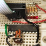
OK – I can write fuses.  Can I get it running with my target 16MHz crystal?  Looks like I need to change CKSEL in the low fuse for a final value 0xEE.  Punched that value into my script, and – it works!  (Yeah, even with that SMT crystal kludged in.)

Recap of lessons learned (besides a review of the “nothing’s ever as simple as it looks rule”):
– The ArduinoISP sketch is a STK500V1 emulator that can program Tinys as well as program and burn bootloaders into various AVR devices.
– Under some circumstances, the DTR pulse that resets an Arduino when you load code into it interferes with ArduinoISP.  A 10uF cap from Reset to Gnd or 120Ω resistor from Reset to +5 will disable auto-reset (by brute force).
– Adding a “hardware” directory in your Arduino sketch directory overrides some/most of what’s in the hardware directory in the Arduino installation.  In particular, I’ve added support for Tinys by dropping additional core libraries there.
– One of the things in that new hardware library is a new boards.txt file that defines the boards you can select from under the IDE’s Tools->Boards tab.  Hacking that file is sometimes helpful.
– There’s a WHOLE lot of stuff in #ifdefined sections to make it all work with lots of processors, speeds, etc.
– The signature bytes check by avrdude is only a safety check.  Disabling it by spoofing the signature byte values in avrdude.conf (or presumably adding -F in the makefile, if you can find it) is only dangerous, not harmful.
– It’s not too scary to run avrdude manually once you find the magic command line switches.  The -n “don’t really do anything” switch is a nice safety feature for playing around with it.  So far it’s the only way I’ve found to burn fuses without a “real” programmer.
– Low voltage serial programming (by bringing Reset low) works (about?) the same on quite a few AVR family chips using the built-in SPI facilities and the SCK, MOSI, and MISO pins.  You can program an ATMega328 that way whether it has a bootloader or not.  You can also use it to burn a bootloader.  You can also burn fuses with it.
– High voltage (bringing Reset to +12 or something with specific timing requirements) serial programming should (almost?) always work, including on chips which have had the RSTDISBL fuse programmed (which allows the Reset pin to be used for I/O).
– We owe a great debt of gratitude to the folks who have added support for other AVR processors (like the Tinys!) to the Arduino environment.  It’s a substantial effort to add processors, poring thru the datasheets and making LOTS of decisions like “Which hardware timer shall I use to implement Arduino function X?” and then writing #ifdef’d code to make it work without breaking anything else.
– Sorry – I still don’t know where I got the core libs I’m using.  They’re NOT from the HLT page link, nor from avr-developers.  They seem to be based on arduino-0022 from the name of the directory: arduino-tiny-0022-0008.  I’ll find the source eventually…

Update 12/6/11:  The core libs I’m using are from Google code here: http://code.google.com/p/arduino-tiny/downloads/list  Finally!

Update 1/2/12:  Two areas of “progress”.

Arduino 1.0 and avrdude
The avr stuff from Arduino 1.0 includes support for 4313, and the tiny core has just (within days) been upgraded to support 1.0.  Unfortunately, I can’t get even my test programs to compile (for tiny) under 1.0.  They’ve succeeded in making a “disruptive change”.  I need progress not disruptive roadblocks, so 1.0 is a non-starter for me.

That’s not to say 1.0 doesn’t have some good stuff:  The avrdude with 1.0 has actual support for tiny4313!  Unfortunately, I still have no clue how the IDE calls avrdude, so I can’t hack it to use the 4313 entry.  The tiny core still doesn’t support 4313, so I still have to lie and say I’m running a 2313.  That’s OK – I’ve made a new board type for 4313@16MHz with the larger memory size, but still with build.mcu=attiny2313.  But that means avrdude also thinks it’s a 2313.  So I’ve copied the whole hardware\tools\avr directory from 1.0 to my 0023 install and hacked its avrdude.conf file to change the 4313 stanza’s part->desc entry to “ATtiny2313”.  (The part->id entry doesn’t seem to matter.  I also changed the 2313’s part->desc entry to “ATtiny4313”, which will never be used, but will keep avrdude from finding duplicate entries.)

The 1.0 install also includes the “NewSoftSerial” library, now renamed with the old standard “SoftwareSerial” name.  Unfortunately, I can’t get that to work with the tiny core.

Serial
Next step is to get some kind of serial working, since the RF gun needs it.

The [24]313 has a real UART, so I thought with a crystal I could get good, fast serial for minimum latency.  But I haven’t been able to get it to support the regular serial stuff for 2313.  If I use Serial.begin(9600) with or without #including <HardwareSerial.h>, the code compiles and loads, but hangs as soon as I issue a Serial.print().

If I #include <SoftwareSerial.h> and instantiate
SoftwareSerial mysoft=SoftwareSerial(7,6)
I can get mysoft.begin() and mysoft.print() to work, but only up to 19200.  It’s total gibberish (to ptelnet on my Palm Centro) at 38400, and about half correct chars at 115200.

I hoped NewSoftSerial – which I understand is interrupt based – might do better.  I downloaded ver 10C, but it wouldn’t compile, with errors about TIMSK0 and TIFR0 not being defined. I spent a lot of energy trying once again to get 1.0 to work just so I could try the NewSoftSerial, but ran into too many incompatibilities.

With 1.0 being no help, I was more desperate to get it to work with 0023.  I chased thru the code, and based on a note in tiny\cores\tiny\core_timers.h, it looks like the 2313/4313 only have one timer, so the mask and flag registers are TIMSK and TIFR rather than the TIMSK0 and TIFR0 expected by NewSoftSerial.  A couple of hacks later, I found that by adding #define TIFR0 TIFR  and #define TIMSK0 TIMSK right after the #definitions of the latter in arduino-0023\hardware\tools\avr\avr\include\avr\iotn2313.h it would actually compile.  And it even seems to work up to 115200!  It’s a pretty gross hack, and it’s a shame not to be able to use the UART, but at least now I have enough serial to try to make a little progress in  getting the processors to talk to the radios.

TinyDebugSerial would be nice to have as well, but it defaults to D2/PA1/pin 4, which is one side of the crystal!  I tried hacking TinyDebugSerial.h to point to port D bit 1 (pin 3), but couldn’t ever get it to work.  Looks like it always? compiles HardwareSerial.cpp, which jumps in to declare the Serial class as HardwareSerial (by including HardwareSerial.h) if any baud rate register is defined – which should be the case for 2313.  I even tried defeating that declaration in HardwareSerial.h, but it didn’t help.  So zero luck getting tinyDebugSerial to work with 4313s, at least so far.

This is a lot harder than I expected.

Update 1/15/12:  Some progress!  I hope I can remember and write down all the important stuff I’ve done. In any event, I’ve got HardwareSerial running at least at 38400 and the TX and RX boards showing they can hear each other (at least TX->RX so far)!

Skipping past days of frustration, here’s some more critical stuff (beyond what’s already described above):

  • Commenting out #includes is tricky  While I was trying to get some kind of bidirectional serial to work with the 4313, I tried several serial libs – HardwareSerial, SoftwareSerial, NewSoftSerial, regular Serial, and at times TinyDebugSerial.  I wanted to switch among them (since none worked right), so I put in a few blocks like this:
    #define NSS
    ...
    #ifdef NSS
    #include <NewSoftSerial.h>
    #define myserial NewSoftSerial
    myserial myserial(0,1);
    #endif

The plan was to turn on which ever block I wanted to play with and use print commands that looked like myserial.println(“whatever”);.  Not quite.  Apparently you can’t comment out #includes that way.  Neither can you comment them out with multi-line /*…*/.  You can’t even get rid of them with #if 0 … #endif.  And of course including headers you don’t want can cause trouble – even if the IDE clearly shows them as commented out!  Single line comment marks like //#include <whatever.h> do seem to work.  Who knew?

  • You have to lie about “memory”  I chose the attiny4313 over the 2313 because it had more “memory”.  I didn’t expect to have much problem using all its “memory” – wrong.  Each type of memory – flash, RAM, EEPROM is a separate battle.My first issue was being able to compile programs larger than 2K.  That was easy – in boards.txt just hack attiny4313at16.upload.maximum_size=4096 instead of the 2048 from the attiny2313 stanza I copied it from.

    Next was being able to actually upload that much to the chip.  After I got past the signature, it was a small step to further hack the 2313 stanza in avrdude.conf to set ‘part->memory “flash”->size=4096’ (up from 2048).  Actually, by running a later version of the avr tools, there was a stanza for 4313, though I had to hack that one so it was used to load a “2313”, since I still have no way to change the command line params to avrdude, so it still thinks it’s loading to a 2313.  I think you have to rebuild the IDE to change the avrdude invocation.

    RAM was hard.  I suspect many of my problems of bizarre behaviors (like valid C syntax not working) were because I was out of RAM.  The Arduino environment is singularly unhelpful in helping you troubleshoot RAM problems.  Basically the stack and heap overwrite each other and bad things happen when the program runs, with no clues at build time.

    The compiler starts at the bottom of RAM with .bss and then the heap.  The stack starts at the top of RAM and works down.  Since I’d told it I was using a 2313, it assumed there was only 128 bytes of RAM, and so started the stack in the middle of the 4313’s 256 bytes – making the top half useless.  How can I find where the stack really starts?

    Since I couldn’t get any serial lib to print values of variables (only  short character strings) I couldn’t just print the address of the first local variable (which lives on the stack) or use the helpful freeMemory() function I found in this forum post.  But you can print the symbol table by running hardware\tools\avr\bin\avr-nm against the binary elf file, which lives (after the most recent compile) in the most recent directory with a name like \Users\Jim\AppData\Local\Temp\build4951313939990712133.tmp as *.elfAvr-nm‘s output includes a nice line like “000000df W __stack”.  (That 0xDF is the 128 bytes in a 2313 plus 0x60 bytes of various registers.)  OK – I can see it.  How to change it to the 0x15f value the 4313 needs to use its 256 bytes?

    I found references to the stack being started at the symbol RAMEND – which is set to the top of RAM for the chip in use.  RAMEND is clearly defined in hardware\tools\avr\avr\include\avr\iotn2313.h.  I changed that #define (of course restarting the IDE after the change) – but __stack remained at 0xdf.  So it doesn’t actually use the RAMEND symbol to set where the stack starts.

    It turns out it’s compiled into hardware\tools\avr\avr\lib\avr25\crttn2313.o.  In a startling bit of good fortune, using a hex editor on the .o file I found the string “__stack” (starting at offset 0x0642), and an instance of the value DF 00 at an offset of 0x0504 (in the version I’m running).  From the appearance of the junk in the area, it looked like those might go together.  Fingers crossed, I changed that to 5F 01, restarted the IDE, recompiled the sketch, re-found the latest build directory, and reran avr-nm.  The line was now “0000015f W __stack” – success!

  • By default TinyDebugSerial uses on of the crystal pins for output   Since I’m using the crystal, that made TDS not helpful.  But this hack to <sketchbook>\hardware\tiny\cores\TinyDebugSerial.h changed that to use the same pin as the UART TX (since I couldn’t get HardwareSerial to work at the time):
  • #if defined( __AVR_ATtiny2313__ )
    /* port A bit 1 (pin 4 - xtal!) - jw
      #define TINY_DEBUG_SERIAL_REGISTER    0x1B
      #define TINY_DEBUG_SERIAL_BIT         1
      */
    /* new: port D bit 1 (pin 3) */
      #define TINY_DEBUG_SERIAL_REGISTER    0x12
      #define TINY_DEBUG_SERIAL_BIT         1
    #elif ...
  • The 2313 support defaults to NOT use the UART  In hardware\tiny\cores\tiny\core_build_options.h for 2313 is “#define DEFAULT_TO_TINY_DEBUG_SERIAL  1”.  To use the HardwareSerial lib, this has to be turned off (changed to 0).  It looks like the timer interrupt flag and mask registers TIFR0 and TIMSK0 I’d hacked in are only needed for NewSoftSerial.  If I use HardwareSerial, they’re not needed.

That’s all I’m aware of right now.
Posted in ATtiny4313 | 7 Comments

Protected: RF starter’s gun

This content is password protected. To view it please enter your password below:

Posted in Rf starter's gun | Enter your password to view comments.

ISP cable for Tiny 85 (and more!)

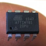
I got the cute little 8 pin Atmel AT Tiny85 working with the Arduino IDE by following steps and hints in this post and playing with a couple of different core libraries.

At under $3 each, this chip is a great way to provide a little programmable control for a project where an Arduino might be overkill. If you use the internal oscillator, you can get five  or even six I/O pins.  In addition to normal digital I/O, it provides up to 3 analog inputs and 2 PWM outputs.  There are limitations (including no easy serial) but you can do a lot with it.

You can write and debug code on an Arduino, change pin definitions to fit the 8 pins on the Tiny,  then download it to the little guy.  There’s no bootloader, so you need some kind of programmer to get the code into the Tiny.  Fortunately, the “Arduino ISP” sketch included with the Arduino development environment is just the programmer we need.  A couple of wires connecting the Arduino to the Tiny (usually on a breadboard) and we’re ready to go.  The details are in the post from hi-low tech above.
One detail not correctly stated on the HLT page is that for Duemilanove you need to block the Reset signal (carried in on the DTR pin in the serial interface from the IDE) to keep it from interfering with programming the Tiny.  The 10uF cap from the Arduino Reset pin to ground prescribed for the Uno works fine.

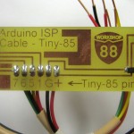
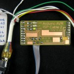
While wires stuck into the female headers in the Arduino work fine, since I expect to use Tinys in a number of projects, I made a sort of mini-shield to make it easier to set up and to avoid the errors I’m sure to make.  I also put the 10uF cap on the little board so there’s one fewer thing to remember.  Labels for which wire goes to which Tiny pin keep me from having to look it up each time I use a Tiny.

I hope to share what I’ve learned in a class at Workshop 88 on using the Tiny 85 with Arduino.  Since the boards are so small, I’ll just make some up and let the students solder the header pins and wires from the cable to the board and have a programming cable take-away.

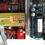
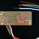
Update 11/27/11:  Since I’m going to be using this cable (and an Arduino) as a programmer for other projects including one with five Tiny4313s, I redid the board to be convenient to use a ribbon cable to the “standard” 6 pin ISP header on the Arduino.  It looks like many of the AVR family do serial in-system programming via SPI – using MOSI, MISO, and SCK (and Gnd) – and using the Reset pin to put the device into serial programming mode.  It’s usually handy to have +5V, so those are the 6 pins on the standard header.  This cable should be useful for several AVR chips – including burning bootloaders to ATMega 328s for Arduinos!

The new mini shield is set up for comfortably hand-soldering a ribbon cable to it, with an insulation displacement female 2×3 connector on the other end.  (Yeah, the one in the picture is a 2×5.  It was midnight and that was all I had – sorry.)  There’s even a cryptic legend showing which wires are MOSI, MISO, SCK, Reset, V+, and Ground (replacing the Tiny85 pin numbers).

I did a quick test with a modified Blink sketch and was able to program a second Arduino (without using its bootloader) from one with the shield/cable plugged on and Arduino ISP running.  (There was initial confusion when the first/programmer Arduino’s LED blinked in addition to the second/target’s LED.  But since SCK/PB5/Pin19/D13 is connected to the LED on all Arduinos, and since the programming cable connects SCK to SCK (as well as MISO to MISO and MOSI to MOSI), D13 on the second Arduino was driving the LED on _both_ Arduinos.  D’oh!)  Also, by modifying boards.txt based on this info, I was able to create a new “board” entry for Duemilanove using Arduino ISP.

Based on the Tiny2313 board profile that came with whatever core libs I’m using (I’ll figure out which ones Real Soon Now!) I should be able to create a 4313 profile with the larger memory sizes, the 16MHz crystals I’ll be using and set up to use Arduino ISP.  With a little luck and if I can just keep from making any dumb layout mistakes putting that header on the 4313 boards, I should be able to program the 4313s!

I’ll post the Eagle files as soon as I can figure out how to use Github.  Thanks for the suggestion, Dave!

Update 12/16/11:  Just an update on usage of the cable and ArduinoISP:  I had used the cable to burn the blink sketch into my “good” Duemilanove  (leading to the success comment above), and it appeared to work fine.  But the next time I tried to use that board, the IDE couldn’t talk to it – giving an avrdude out of sync error I really wish I’d captured.  What I believe happened is that while it burned the code to the board, it overwrote the bootloader.

Since I had the cable and a spare Arduino (a Diavolino), I thought it would be easy enough to burn a new bootloader to my Duemilanove, presumably fixing it.  I ran into problems I should have anticipated, but will help me remember for next time:  I’d been using the Diavolino as an ISP (for some 4313s), but I wasn’t certain of its state, so I figured I’d just reburn the ArduinoISP sketch to it for good measure.  That didn’t work – another avrdude out of sync error.  Have I really blown the bootloader on both my Arduinos?

No.  The Diavolino still had the cable mini-shield attached.  That, of course, contains the 10uF cap that defeats the IDE’s resetting the board after a download, which interfered with downloading the ArduinoISP sketch.  I removed the shield, and burned ArduinoISP with no problem.  Then I put the shield back on, connected the other end of the cable to the Duemilanove, and burned the bootloader to it with no problem.  After that I could talk to the Duemilanove from the IDE, which is what makes me think I overwrote the bootloader in the first place.

Takeaways:
– Burning a sketch to an Arduino through the ICSP with the cable works, but will overwrite the bootloader.  There’s probably a way to set a load offset to avoid that, but I don’t know what it is (at least not yet).
– Trying to burn a sketch (ArduinoISP, and presumably anything else) to a board with the cable/shield on it won’t work.  Take the shield off first.

Update 4/19/14:  These mini-shields/cables have been a good success.  We used 4 of them for code burning stations for the Thotcon badges, and I’ve handed them out at all the Tiny85 classes I’ve done.  There are 2 upgraded versions.

NewW1LED1391This is what I handed out at the most recent class.  It’s just the same with the addition of one LED (and resistor) on pin 9 for the heartbeat.  I didn’t even know about the LEDs until I happened to be looking thru the Arduino ISP sketch one day.  The heartbeat LED is the most useful: if it’s “breathing”, the ISP sketch is loaded and running.

MyGoodCable1394The one at the right is my “good” mini-shield, and is the one I routinely use (if I can find it).  It has all 3 LEDs, and the ideal cabling arrangement:  There’s a ribbon with a 6 pin 0.1″ female coming off the board so it can be plugged directly into anything (like an Arduino with a bad bootloader) that has a 6 pin AVR ICSP header.  But there’s also a cable with a 6 pin male that plugs into the ribbon, but provides breadboard-friendly ends for when those are needed.  The tag even shows the color/pinout for a Tiny85.  Now that I’ve played with it, the 3 LEDs are overkill, and I think this is the only one I’ve made up that way.  (Several students have opted to put a ribbon and a 6 pin female on, though.)

Posted in Tiny 85 stuff, Workshop 88 Stuff | 7 Comments