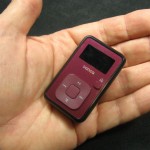
 Here’s (one of) my shiny new $20 4 GB Sansa Clip+ MP3 recorder/players from Woot. It’s smaller than I’d pictured – but that’s fine. The little “R” melted into the back of the clip might well mark it as refurbished, but I don’t know.
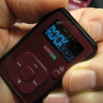 The first step was to install the open source RockBox firmware. That provides essentially all the features the hardware is capable of – far more than the manufacturer chose to expose. It’s fantastic. I even thanked them with a donation.
The only recording input is a built in microphone. We have to open the device up to somehow get an external input to connect to where the mic connects.
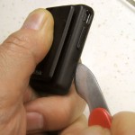
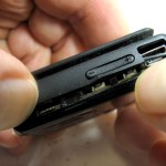 A good tool to start cracking the case open was a watch case opener from a cheap set of watch repair tools from Woot or somebody. After working carefully all the way around, I could peel it open. I only broke one thin place near the USB connector hole.
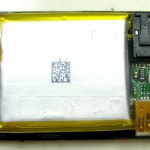
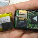 With the back off, the battery dominates the view. The black headphone jack is upper right; the USB connector lower right. There’s a screw that holds the PCB in place hidden under the battery, so we have to take it off. There’s some double stick foam that holds the battery to a large chip. Gentle peeling got the battery separated from the rest. You can see the little mic at the right that we’ll have to remove.
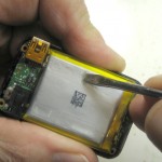 The outside of the battery had two little strips of double sided tape – probably to make it really hard to get the case apart. (It worked well!) After the battery was loose, those bits of tape stuck to everything on the bench, so I scraped them off, trying not to poke holes in the battery 🙂
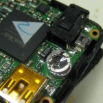
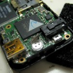
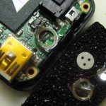
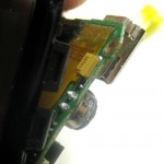 I managed to lift the PCB enough to see where the mic was soldered in. I couldn’t get to those connections easily, and it was some trouble (and danger to the flimsy ribbon that connects to the display) to get the PCB lifted even this far, so I hoped I could get the connections I needed from the other side. To do that, I planned to carefully destroy the mic, hoping to expose the two pins on the other side of the board from those solder blobs. If I could cut everything else away, I could solder to those pins without needing to pull out the PCB. Since I’ll very likely do this same hack to more of these great devices, I’d like it to be as safe and easy as possible.
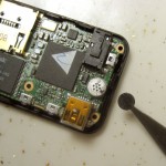 Dissembling the mic started by peeling off the dust cover. The aluminum case had no seams at this level – so it’s time to cut it open. Eventually I could see the solder points I was after, but it didn’t seem like I could remove enough to use them. Bummer.
Back to Plan B – soldering to the back. I carefully heated the 2 solder blobs (at the same time) and pulled what was left of the mic off. I ran some wire scraps through the holes to clean them out.
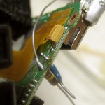
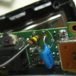 OK – what do I connect to it? The little electret mic certainly has DC to power it, so I’ll need a series cap. There’s often a 1-2K resistor as a load for the mic, so that’s probably about the input impedance. Taking a wild guess, I decided I’d try 100K in series to drop the signal to more like what a mic input would expect. I soldered a cap and a resistor to the old mic pads.
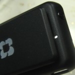
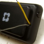 This is still prototype, so while eventually I need a cable with a good strain relief, all I needed at the moment was to get the wires out of the case. The hole for sound to reach the mic was (obviously) right in front of where the mic was – which was also where my new leads were. I drilled the hole out a little bigger, and relieved part of the top of the clip right there as well. I brought the resistor lead and a bit of wire soldered to the short cap lead out the hole and snapped the case back together.
I pushed the button – and it still powered up – a good sign. I used the USB connection to drop a couple of MP3s on it, and they played nicely. Then I stumbled through the menus and figured out how to get it into record mode. (Yeah, it’s probably in the doc somewhere.) Some such recorders will run in full duplex mode and let you hear on the headphone output what’s going into the record input. I put some audio into the wires on the back – and sure enough, it came out the headphone jack.
My interest in that feature was to test whether the device had AGC. By listening to the output while varying the input level a lot (20 db or more) it’s easy to hear whether there’s any AGC leveling the output. I did that test, and (a little to my surprise for a voice recorder) the Sansa didn’t seem to have AGC (at least under RockBox). Not a problem – that’s what my recording preamp/AGC/limiter is for.
With audio coming in and a little fiddling with the input level and the gain control in the recorder, it was recording! RockBox let me set the sample rate and bit rate to my customary values (44.1KHz, 96Kb/sec, mono).
As a sanity check on the input level (and whether my 100K guess was in the ball park), I ran some audio through my good white recording preamp, set to normal level according to its LED meter. Its output went to the Sansa input. A little fiddling with the gain in the Sansa, and I could get ideal record level. The 100K was at least an acceptable value.
A test that remains is to see how long it will record on its internal battery. That will give me some insight into what I would need as a massive single battery to last a whole weekend.
As an added and welcome bonus, the Sansa even timestamps the files it records! My stalwart Iriver 800s don’t do that. I think some other model does (maybe a T30??) but that one had other fatal flaws. This one has it all!
My hat is off to fellow square dance recordist Ray Olszewski from Palo Alto who tipped me off to these great recorders (some hacking necessary). His Altoids-box-housed recorders piqued my interest, and when I asked he told me all about them and the mods he and Bill Hoover had made to them. Thanks Ray and Bill!
With the exception of final mechanical dressing of the input lead – which should be easy – this hack as been a total success!
Update 9/20/11: Did a battery test with a freshly fully charged battery, recording at 96Kb/sec continuously. Incredibly, it recorded for about 14.5 hr, consuming just under 600MB (of its 4 GB!). Source was a ~15 min recording with 11 sec silence at the beginning continuously looping, played on an Iriver 890. While it did split each loop of the playback to a separate file, I haven’t gotten the trigger stuff to work right yet. But I haven’t put a lot of time in tweaking it yet. I expect I’ll get it to do just what I want. Level is maybe a little low – that 100K may need to be cut to 50 or 22K. That’s easy.
Very interestingly, even with less than a new battery, that would be enough recording time to do a full day without even shutting it down between sessions – even in the worst case hum/noise scenario! If I do integrate it with a bigger battery (that also runs the recording preamp/limiter), it looks like it won’t have to be a huge one. One of the real hassles of recording in multiple halls is running between halls at the end of each session to shut down – and then again to turn them on before the next session. If I can just leave them running, that’s a huge simplification of my duties. I’m happy enough to set them up before the first session and take them down after the last session each day to dump recordings and recharge batteries. This is about perfect!
Update 10/15/11: Having decided to remove the battery from the Sansa housing and provide a single “large” battery to power both the recorder and the electronics, I needed to be sure I understood what connections I’d need to the Sansa. Two questions:
– Is the ground end of the mic input really connected to battery minus?
– Will it play (very likely) and charge happily (the real question) if the 3rd (blue) wire from the battery is disconnected?
That third wire is usually connected to a ~10K negative temperature coefficient resistor in good thermal contact with the battery so the charging circuit can abort if the temperature is too high (or possibly too low). The other end of the resistor goes to battery minus. The battery pack I’m planning to use (an 850 mA-hr unit from Spark Fun) only has 2 wires, so I care about whether that’s enough to get the Sansa to run. But since I’m also hoping to use the Sansa’s charging circuit (even though the new battery is 3 times the capacity of the original), I might need to spoof that NTC resistor if the charger won’t charge without it.
So I opened it up again, first checking continuity to the low side of the mic. The first test was whether I’d see battery voltage between B+ and mic low. I did! So there’s at least a pretty low resistance DC path from mic low to B-. With that reassurance I used a continuity checker and verified a very low resistance between the two. Great – that’s one fewer wires I have to bring into the Sansa – and since the low side of the audio of the preamp is at ground/B-, I don’t have to worry about connecting them.
Then I unsoldered the blue wire from the battery. It still played, as expected. To determine whether it would still charge, I measured the voltage across the battery terminals before and after plugging the USB connector into the PC. The voltage went up – so yes, it’s charging. Perfect.
Since I’m already putting a cap on the output of the preamp, I just added a resistor to the board, and now I don’t need any additional parts inside the recorder. And since the low side of the mic is really B-, after I pull the mic, I only need to solder one wire in – to the mic high side.
After considering various connectors, I decided that this would be a dedicated device, and essentially always connected to one of my preamps. That let me take the easy way out and just provide 3 normal 0.025″ square pins coming out of the bottom of the device. By providing good mechanical mounting for them inside, those 3 pins can become an integral part of the mounting mechanism for the Sansa. Unusual, but completely workable for this application.
To use a single battery for the electronics and the Sansa, I removed the battery from the Sansa. I only need 3 connections out of the Sansa: Ground, V+, and Audio In. Removing the battery gives me a place to mount a little PCB with 3 normal 0.025″ square pins sticking out the bottom of the unit. The pins are on 0.1″ centers, but skipping 2 pins between each, giving 0.6″ between the outside pins. These pins will be a primary part of the physical mounting, so having them farther apart provides a more secure mount. I left a generous amount of copper for each pin to provide good mechanical strength from the soldered joint.
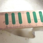 I measured the pins, how far they should stick out to plug comfortably into a female header strip (0.25″), where the board would be located in the Sansa, and included a mark on the PCB layout for where the end of the pins should be. As long as I was making up a board, I laid out 3 copies, and found a scrap of board that would just fit. Too lazy to make another board holder for etching, I just bent an existing one (from the LED display latch boards) to fit this one. Worked fine.
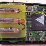
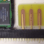 To ensure correct alignment of the pins, I plugged them into a female header to hold them while soldering. Here’s the unit with new leads for battery + and – and a yellow one from the old mic location for audio in. A little hot melt to hold the board in place, and we have electrically and mechanically sound pins! (A keen observer will notice that the board obscures one of the screw holes. I didn’t,
 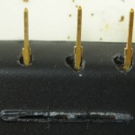 but was able to clip the corner of the board so I could put the screw back in.)
Sorry about the ugly holes.
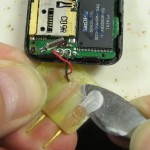 When I modified the second Clip+, I was sloppy when I pressed the little PCB down on the hot melt, and it ended up crooked. I had little choice but to removed it and reglue it. Guess it was a good thing I used hot melt instead of epoxy.
OK – that was on one of the (4GB) Clip+ devices I got from Woot. There’s also a regular Sansa Clip, with no micro SD slot. If those work as well, it increases the collection of Ebay offers I have to choose from to get more. I got one and took it apart.
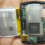
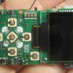 The physical layout is a little different, with a combo hold/power switch, and a shield over almost the whole main board. The battery is still glued (double sided tape) to both the guts of the unit and the case, continuing to make it a challenge to open the case the first time. After you remove the battery and pull the (slightly differently laid out) screws that hold the main board, the display stays on the main board, so getting to the mic solder contacts is much easier.
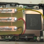 The shield (at least after roughing it up with a bit of sandpaper) makes a fine surface to glue the little pin-holding PCB to. I did have to cut off one of the plastic hooks that lets the case snap together. Overall the Clip is probably more desirable than a Clip+, between easier access to mic solder points and possibly being a little cheaper from being a little older and lower functionality.
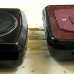 One thing I didn’t see coming was that that shield in the Clip is not at exactly the same height as the SD card socket I was gluing to in the Clip+. A little judicious bending should fix it, but it was a surprise the first time I tried to plug the Clip into one of the recording preamps into which the Clip+ fit fine.
While the original two units had their pins coming straight out, to be plugged into a hacked down socket, I think later units will have the pins bent to be essentially flush with the back of the Sansa, and I’ll just solder them to the recorder PCB.

Pingback: Adding an external audio input to the Sansa Clip+ | You've been blogged!
Pingback: Adding an external audio input to the Sansa Clip+ | CisforComputers
Pingback: Recording preamp/limiter – with battery test | Jim's Projects
Pingback: DIY by grehan - Pearltrees
Interesting article! I have a clip+ myself and was wondering if it could do line-in recording. Seems like it can, with hacking 🙂 The only thing I’m missing here is stereo. If I understand correctly, you only found a way to record mono. Have you later found a way to do it in stereo?
My only target was mono, so that’s all I’ve tried for. The chips certainly support stereo, as does RockBox. A hack to actually get stereo in would probably involve soldering the input lines directly to one of the chips.
Good luck!
Jim
Pingback: Recording preamp/limiter – with battery test | Jim's Projects