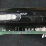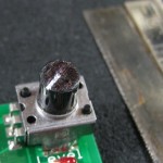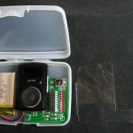
Supermate DC-6 charger “USB” port – NOT!

As part of a plan to upgrade a couple of 18V NiCd powered devices to LiPo, I just got a Supermate DC-6 charger from HobbyPartz.  Pretty flexible, cheap, seems to work OK.

On the box, on the label on the front, and even on the manufacturer’s web site, it says it has a USB port to allow monitoring the charging of your batteries.  Cool.  Yeah, the port is shared so it’s either for USB or for an LM-35 temperature sensor, but I can live with that.  I saw several posts asking for where to get or how to make a cable for it, so I knew there would be a little work involved, and I can live with that, too.

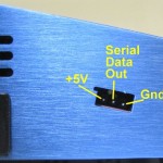
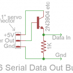
The port is brought out on a recessed 3 pin 0.1″ male header.  (RC folks would think of that as a servo connector.)  I don’t think there is any way to run a USB port on 3 pins.  (OK, I suppose if you didn’t bring +5V out.  But I’ve never heard of anybody doing that.)  I suspected TTL serial data, but needed proof.  So I put the charger into USB mode (Set User Program -> USB Enable) and looked at the pins with a scope.  Five volt (TTL) serial data!  And it’s transmit only.  Here’s what the connector looks like and its pinout:

I’d read that the SkyRC Charger Monitor software for a Skycharger B6AC+ would work, so I downloaded it from the HobbyPartz page for that charger.  Unfortunately, when I connected the charger to a standard TTL serial-USB adapter (that I routinely use with Arduino clones and other stuff), the software showed no connection.  A serial port monitor also showed nothing.

Looking at the signal while it was connected to the USB adapter, it was clear the voltages weren’t right.  I could see what looked like serial data with high levels around 5V, but the low levels never got below maybe 4V.  That’s never going to work.  Bummer.  The input to that adapter goes straight into the CP2102, so I’m surprised it didn’t work.

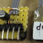
So I made up a really simple non-inverting buffer to drive the USB TTL serial adapter and hooked it up. (Although it only uses 2 wires, the buffer’s TTL level output is pinned out on a 6 pin header like Arduino clones usually use so it plugs into a standard serial adapter.)  I could see some kind of binary data on the serial monitor, and the Skycharger software works!  Because the data is binary, I couldn’t really tell what the baud rate was, but 4800 and 9600 gave the best results.  I couldn’t find any software that would show what baud rate the Skycharger app set the port to, either.  It’s not worth reverse engineering the protocol, since I have something that reads it.  I’m not sure that software will be particularly helpful for my applications, but at least I have a way to use it.

I’ve read that others have successfully used the “USB cable” for the Skycharger.  I’m very curious what the input circuitry on that adapter looks like.  (Update 8/14/12:  I asked about the adapter on live chat at Hobbypartz.  They said there’s no part number, but if I asked “tech support” they might be able to special order it for me.)

Anyway, I wanted to set the record straight:  That port is absolutely NOT a USB port.  It is a serial write-only/”broadcast mode” under-spec TTL output.  With correct adapter circuitry it can be used with a USB port.  Or, for that matter an Ethernet port.  Or a Firewire port.  Or about anything else you want.  With the right adapter.

Posted in LiPo Conversions | Tagged , , , , , , , | 2 Comments

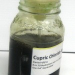
Making cupric chloride etchant – with 35% hydrogen peroxide!

I scored some 35% “food grade” H2O2!  I tried a few local health food stores with no success, but finally found a link to places that sell it.  I called Life Spring Health Food in Chicago and they had it – for $14.95/16 oz.  Not cheap, but not terrible.  (At 200 ml to make a liter of etchant, this is more than enough for two liters.)  The drive into the city to get it was less than pleasant, but I came home with a nice cold bottle of it.  (It should be stored in the refrigerator.)  (See comment at end for 12%.)

I just tested the first recipe batch of etchant and freed up the “reaction vessel”, so I’m close to trying a batch with this oxidizer.
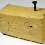
I also ran across a wonderfully simple insulation slicing bulk wire stripper on YouTube.  (Judging from the number of wire stripper clips, there must be quite a few people selling bare copper wire for the scrap value.)
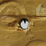
OK – it took a couple of tries to get the alignment right, but it’s much better than my previous stripper because it’s trivial to adjust, and because the hole provides a much better guide for the wire than the V-groove in my old one.  The sharp point on a drywall screw works quite well to slice the insulation.  I haven’t stripped the 16′ of wire for this new batch yet, but I bet it will go very quickly.

Judging from how fast the first batch got green with just a little H2O2, I’ll be really interested in how fast this goes.  Updates to follow!

Update 8/7/12:

DON’T DO THIS!

Updates to follow after I neutralize the acid and clean up.

Later:  The recipe to make CuCl2 with drugstore 3% H2O2 is to put everything in a container, turn on the bubbles and check back every few days.  That REALLY doesn’t work with 35% H2O2!

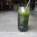
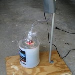
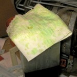
I used the reaction pop bottle, top funnel, copper holder and air stones from the last run (with 3% peroxide), but skipped the splash disk.  To help contain the aerosol, I made a skirt of paper towel, folded to about 3″ wide, 3 layers thick, wrapped around the top edge of the funnel, secured to itself with a piece of duct tape.  It just touched the shoulder of the bottle with the funnel in place.  That’s the white looking top in the clip below.

I put 250 ml of (cold) 35% H2O2 into the bottle, and carefully added 750 ml of 10M HCl.  Kind of yellowish, but it didn’t seem to do anything bad.  I went to get the “containment vessel” – a cut down gallon HDPE jug – to take it outside, and in the minute or so I was gone the acid/peroxide had started bubbling very actively.  Not boiling – just (I expect) H2O2 decomposing and giving off O2 .
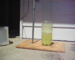
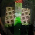
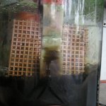
I hurried outside with it to get the copper in before I lost any more H2O2.  Fortunately, I had set up a camera to record how quickly the solution became green.  Unfortunately, I’d cheaped out and set it for pretty low res.  Here’s what happened next:
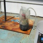
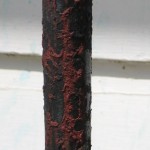
The boiling acid didn’t attack the PETE pop bottle, but it did soften it enough to deform under the (small!) weight of the top funnel/copper holder.  The previously clean galvanized EMT that supported the air pump got substantially redecorated.  (You can see it happen in the clip about 50 seconds in.)
The interesting good fortune was that Steve Finkelman of the Evanston Mini Maker Faire (and PS:1) had asked/required that I prepare a “safety kit” for my PCB etching demo there yesterday.  I did my homework, and had prepared two bottles, each with about 3 moles of dry NaOH (lye from the hardware store) – just enough to neutralize the ~3 M acid in one liter of etchant.  (I had two liters with me.)  The bottles were still sitting around.

Doing a little quick math as the acid boiled, I figured the 750 ml of 10M acid was about 7.5 moles (actually a little less, since there was still some in the reaction container), and I had about 6 moles of NaOH in the two bottles.  Close enough.  I dumped the two bottles into a 5 gallon bucket and turned on the hose.  The total amount of water didn’t really matter – the neutralization would happen mole for mole, whatever the concentration.  I scooped and sloshed the NaOH solution all over (last half of the clip) and then hosed it all down some more.

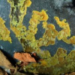
The prettiest part was some almost fractal-looking patterns in whatever toxic sludge was pooling at the edge of the blacktop driveway.  Other places it was blobby rather than spikey.  Now stop taking pictures and hose this crap down to the street.  And hose the sidewalk off well enough that somebody doesn’t come asking embarrassing questions about what happened.
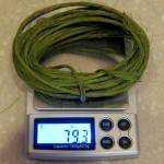
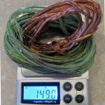
OK – so how much copper salt did I really end up dumping into the water table?  I knew I started with almost exactly 150 g of copper (‘cuz that’s what the recipe called for).  During the couple of minutes the copper was in the bath, about 70 g had dissolved.  That’s all split between what soaked into my grass and what got washed down the sewer.  I think I’d figured a typical PCB would have about 0.5 g copper etched off, so that’s around 140 boards’ worth of copper salts added to the water table.  That’s probably approaching the number of boards I’ll etch in my life.

I guess that means I could have not ever bothered with the cupric chloride, used any other etchant, and just dumped the all the toxic remains down the drain with no net difference on the environmental damage I caused.  Sobering.  I wonder what the legal requirements are for reporting chemical spills.  <googles…>  Looks like the Reportable Quantity of even some of the nastiest substances is 1 pound (and up to 5000 lb for others).  So at least they probably won’t be knocking on the door in the middle of the night.  Good.

As for the recipe to make this wonderful etchant using high concentration peroxide, there clearly need to be steps to control the reaction rate – and the heat produced.  Maybe running it in an ice bath and adding the peroxide just a little at a time?  I was hoping the strong peroxide would get us past the user-unfriendly several days it takes the reaction to run with the drugstore stuff.  Requiring an ice bath and the maker to come to add some more stuff to it once an hour for a couple of days isn’t much of an improvement!

When all was cleaned up, I had maybe 30 ml of ugly brown liquid in the bottom of the reaction bottle.  It was probably acid and copper salts and couldn’t be dumped down the drain, and I didn’t want to deal with it, so I just put it in a bottle and set it aside.

While I still haven’t found any 6% peroxide, maybe I should dilute some of the 35% and try a run with 6% to compare overall time with the batch I made using 3%.

Guess I’ll have to think about it for a while.  I have another 250 ml of 35% H2O2 (and lots of acid and wire), but after cleaning up today I’m not very anxious to try it again just yet.
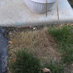
Update 9/17/12: One bit of fallout from the acid fountain is the grass immediately next to where most of the acid hit the ground.  While it stayed green for days or maybe a couple of weeks, it eventually succumbed to the abuse.  I’m not sure whether it was the PH change or the copper salts, but it’s in pretty sad shape.

Update 8/10/12:   OK – second verse, same as the first – but with more math 🙂

Let’s try to get a handle on how much heat is given off in the reaction we’re trying to run, with the goal being designing a way we can run it fairly quickly while keeping things boring.

If we take the heat of formation (the heat absorbed (or if negative, given off) per mole to make a compound from its elements) of all the products of a reaction and subtract the heat of formation of all the initial reactants, we get how much heat is absorbed or given off.  Here are the values of the compounds of interest:
HCl (aqueous):     -167 kJ/mol
H2O (liquid):         -286 kJ/mol
H2O2 :                     -188 kJ/mol
CuCl2 (aqueous):  -172 kJ/mol
Cu:                           0 kJ/mol – by definition

The reaction with peroxide as the oxidizer (with heats of formation) is

4 HCl  +  2 Cu  +  2 H2O2  ->  2 CuCl2  +  4 H2O
4*(-167)  2*0  2*(-188)          2*(-172)     4*(-286)

We end with -1488 kJ and start with -1044 kJ, so we have 444 kJ given off per 2 moles of Cu dissolved.  For our 1 liter bath, we used 2.4 moles of Cu, so with our quantities, we get 533 kJ given off.

It takes about 4.2 kJ to heat 1 kg of water by 1 deg C.  (That’s one “large” calorie.)  Concentrated HCl (30% by this table) takes only about 2.6 kJ.  Our 533 kJ would heat the acid about by 205 deg C.  Since it started at ~25 deg C, that’s way more than would be needed to heat it to its boiling point of around 90 deg C.  All of that essentially says that yes, we should have expected boiling acid (if we’d done the math).

Our 150 g Cu, with specific heat of .39 J/g, would take about 0.6 kJ to heat it one degree.  Adding that to the acid’s 2.6 kJ/kg along with the fact that we only have ~0.75kg, we have a specific heat for all our initial reactants of ~2.6 kJ/deg C.  As the 250 ml of H2O2 is added and reacted to water, it will add ~4.2*0.25= 1.05 kJ/deg C for a final specific heat of ~3.7 kJ/deg C.

We need to get rid of that 533 kJ and keep the reaction from going crazy.  I’m thinking of a two-part approach:
– don’t allow so much heat to build up in the first place, by adding the H2O2 just a little at a time;
– take the excess heat away with an ice bath.

Now the heat of fusion of ice (energy needed to melt from ice at 0 deg C to water at 0 deg C) is 334 J/g, or 334 kJ/kg.  So our 533 kJ would melt 533/334= 1.6 kg of ice.  That’s a manageable amount.  So I suggest that by adding the H2O2 a little at a time, keeping the reactant bottle in an ice bath, monitoring the temperature and allowing it to cool before adding more H2O2 , we could control the reaction fairly well.

What’s “a little at a time”?  Let’s say we didn’t want the temperature to rise to more than arbitrarily 75 deg C, and let’s use our reactants’ effective specific heat of 2.6 kJ/deg C for the acid plus copper.  Starting at say 25 deg C, we can let it heat up by 50 deg C.  To heat our reactants by 50 deg C takes 50*2.6=130 kJ.  (More as the H2O2 is added.)  If our whole  250 ml H2O2 produces 533 kJ, adding it in 4 doses would keep us down to ~133 kJ per dose.  Close enough.

Specifically:  Put the copper along with a thermometer into 750 ml of concentrated acid in a 2 l pop bottle, and put the pop bottle in an ice bath with at least 1.6 kg ice available.  Add the H2O2 (carefully!) 60 ml at a time, waiting for the temperature to drop back to around 25 deg C before adding the next dose.  And do it outside.  Sounds like a plan.  Not a great plan considering the goal of a simple-to-implement recipe, but at least one that probably won’t get us into trouble.  Next step is to try it.

Update 8/10/12: The  cut down 2 liter bottle I used for the acid fountain is pretty misshapen, but it’s about the only clear bottle I have, so I reused it for this more reasoned experiment.  I didn’t expect to need aeration, so a simple holder for the copper hammock was all it needed this time.  I added some new copper to the remains from last time to get back to 150g.
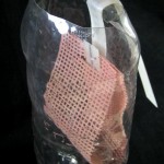
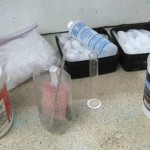
With all the stuff laid out outside (I wasn’t even going to put the acid in indoors this time), the copper already in the bottle and the camera set for higher res than last time, I got under way.

I got good videos of each of the four additions of peroxide, but they were too boring to include.  Boring is good.
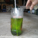
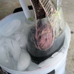
The addition of the first 60 ml of peroxide started to turn the solution green immediately.  After maybe 10 seconds, it started to bubble vigorously, but not dangerously.  The temperature had gone from 25 to about 50 C at this frame capture.  It got up to around 85 C by the time it settled down maybe 2.5 minutes after the peroxide went in.  I put it in an ice bath then to cool it down for the next round.  All those bubble cost oxygen from the H2O2.  Looks like even the 60ml was too much.
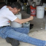
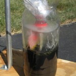
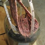
Each successive addition of 50-60 ml of peroxide produced less vigorous bubbling.  I checked the temperature a lot waiting for it to cool back to around 25C to do the next round.  Here’s what’s left of the copper after the second peroxide dose.
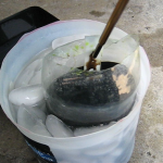
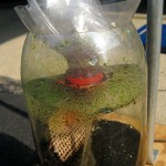
After the second round there was apparently enough CuCl2 to significantly attack the remaining copper during the maybe 5 minutes while it cooled from a peak around 70 C to baseline 25 C.  This frame capture shows that there was a lot of (brown) cuprous there.  Very interestingly, the next addition of peroxide cleared up the brown – oxidized the cuprous to cupric – nearly instantly.  Not surprising that a strong oxidizer would do that, but to a guy  whose reaction would be “Ugh – look how brown it is.  Better turn on the air pump and come back and check on it in a couple of hours!”, it was an amazing transformation.

Aside from the instant brown->green changes, the third and fourth peroxide doses were uneventful, with almost no bubbling on the last one.  I think the peroxide decomposition is very temperature dependent, being much faster at higher temps.  Since the decomposition is exothermic, it can become unstable.  I suspect strongly that was part of the show last time.  That probably argues that (especially early on) it would be good to start with cold acid to minimize the wasteful loss of peroxide due to decomposition.

The copper was almost all gone after the bubbles settled after the final peroxide addition.  At that point I put an air stone in to provide agitation, rigged a very crude splash guard for the misshapen bottle mouth from a little plastic box, and let it bubble for a couple of hours to dissolve the last of the copper.  It took another 10 hours or so (this time after transferring it to my regular tall etch/aeration tank) to clear the brown to green.

Overall it worked, but it felt a lot more like doing a chemistry experiment than following steps to make something useful.  I think the approach could be further improved – perhaps by starting at lower temperatures and adding the peroxide in smaller quantities to keep the temperature down so the peroxide has time to react with the copper instead of decomposing uselessly.  But that’s so much of a hassle I don’t know if it’s worth trying.

After everything was cleaned up and aerating, I came across the bottle of left over crud from the first 35% peroxide fiasco.  Thinking about it, there shouldn’t have been anything in there but acid and copper, so the ugly brown was almost certainly just cuprous chloride.  I work with this stuff (now) and know what to do with a jar of acid with cuprous chloride in it:  You bubble air through it until it turns green.  So I did, and it did.  I haven’t checked its acidity and specific gravity yet, but I expect it’s pretty much just a little more usable etchant.
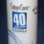
Update 6/25/17: I found a good source for 12% H2O2: Sally Beauty sells a 32 oz bottle of 40 volume “clear” developer for about $5.  I got a bottle just to verify that they weren’t going to give me grief for not being licensed or something.  No problem.

I don’t have the math for a recipe (yet), but this should be a fine starting point, and I’ll use it for my next batch.  Of course we still need to be quite concerned about heat.

As a more general comment, I’m still using what I made up a few years ago as my standard every-day (OK, every few weeks) etchant.  No adjustments – just seems to work fine.  It actually works as designed!

Conclusions

This section is the beginning of a full summary, and will probably be moved to the top of some post.

The goal and initial experiments

The goal was a simple recipe that would allow anyone to make cupric chloride etchant using easily available materials and with minimum effort and high probability of success.

The initial quantitative chemistry led to the realization that we couldn’t make a recipe using “drugstore” 3% H2O2 that would react with all the copper using the quick, clean H2O2 as oxidizer.  The reaction would have to proceed in two phases: one making as much CuCl2 as the limited H2O2 would allow, then using that CuCl2 to dissolve the rest of the copper.  That second phase was slow – several days – for two reasons:
–  limited H2O2 only let us get ~10% as much CuCl2 initially as we would have liked;
–  the second phase was throttled by first making cuprous chloride, then oxidizing that to cupric by bubbling air through it.  But the reaction would eventually finish, and produced good etchant.  This is a viable recipe.

Using a slightly higher concentration of H2O2 (like 6%) should help by making more CuCl2 in the first phase.  (Note that I haven’t tested the process using 6% H2O2.)  That reduces the amount of copper we need to process in the second phase, speeding completion.  It would seem like having a higher concentration of CuCl2 would also further increase the rate of the second phase because we’d start with more CuCl2.  But I doubt whether the higher concentration helps much:  I suspect we rapidly reach saturation of cuprous and are throttled by the rate our aeration can oxidize that Cu+ to Cu++.

That argues that to get “done” more quickly we should maximize the aeration oxidation.  More air should help, as should smaller bubbles (more surface area), a taller skinnier container so the bubbles contact more liquid, and probably running at higher temperature.  Those make sense, but are untested.

The long reaction time using 3% peroxide led to the idea of using sufficiently concentrated H2O2 that we could react with all the copper in the first phase, substantially reducing the time it takes to finish.  The quantitative math says that we could put enough 35% H2O2 in to react with all the copper.  But using the simplistic approach that worked fine with drugstore H2O2 of dumping all the reactants in a container and letting them react DOES NOT work with 35% H2O2.  The reactions are highly exothermic and quickly destroy the peroxide, if not the whole reaction vessel.

A more complex methodology using an ice bath to control the temperature and adding the 35% peroxide in small quantities works, but requires a fair amount of effort and isn’t really in line with the goal of a simple recipe.

Lessons learned along the way to the recipe

Bubbles  If you’re going to be using this etchant, you absolutely will need some kind of aeration setup.  An aquarium pump and air stone work fine.  As soon as you etch anything, your solution will turn brown with cuprous chloride and you’ll have to aerate it to get it back to green.  Turning the air on, walking away, and expecting to come back hours later to pretty green etchant is such an ordinary part of the rhythm of using this stuff that including that step in the recipe for making the etchant is completely not a big deal.

And since you have to have a bubbler, it’s really convenient that those same bubbles are a great way to provide mechanical agitation to make the process of etching boards quicker and more uniform.  A free win!

35% peroxide  This is interesting stuff.  It’s great that it makes it possible to dissolve a lot of copper fairly quickly to make new etchant.  But along with it come two problems, both related to heat:
–  Since it reacts so quickly with copper in a very exothermic reaction, using it releases a lot of heat very quickly into your  under-construction etchant.  You MUST take this into account (and get rid of some heat!) when making new etchant with it.
–  It decomposes into water and oxygen in a reaction that occurs more and more quickly as temperature goes up, and is also very exothermic.  That means once the temperature is high enough for it to start decomposing (evidenced by bubbles), the decomposition heats the solution even more, causing even more rapid decomposition.  When this happens, the oxidizing power you paid for in buying the 35% stuff and on which you are counting to dissolve the copper is literally going up in smoke before your eyes.  (OK, going up in a colorless gas.)  You really don’t want this to happen.  How do you prevent it?  Keep the solution cool!

After the cupric chloride concentration has built up a bit, you’ll have a fair amount of cuprous chloride built up while you’re waiting for it to cool down after adding some H2O2.  The next dose of H2O2 will go in part to oxidizing the cuprous, allowing you to use a larger dose.

Worry about heat!  Doing the quantitative math of how many moles of this you need to make a mole of that is a great starting point, and gives you good answers about how much of each reactant you need to start with.

But with exothermic reactions like these, you really also have to do the rest of the math to figure out how much heat is given off.  And if you didn’t bother to find out whether the reactions are exothermic, that’s your fault!  I was VERY lucky there was no more damage (or injury)  than there was when I stupidly ignored this rule.

Recommendations

Unless you really need the etchant today, I’d just go with the 3% peroxide and live with the fact that it will take several days to complete.  If you can find 6%, that’s probably fine (but that’s not verified) and will finish up sooner.  Here’s the recipe to make 1 liter:

– 16.5′ 12 gauge stranded copper wire (stripped)
– 750 ml 30% muriatic acid
– 250 ml 3% hydrogen peroxide

Put it all in a reaction container with the copper suspended above an air stone and a splash guard at the top.  Turn on the air and leave it on.  It should live outside for the first couple of days – the initial fumes are bad.  It will start out light green, but quickly become muddy brown and stay that way.  It’s done when it’s a deep, clear, pretty green.  It will take several days.

If you’re into instant gratification and  insist on using 35% peroxide, here are some suggestions.
–  Use the recipe above, but use at least 200 ml of 35% H2O2.  If you use less than 250 ml of peroxide, make up the difference with water.
–  Keep the container you’re making the etchant in in an ice bath to control the temperature.
–  Add the peroxide in small doses, letting it cool between doses.
–  Do it outside!  The fumes are very bad, especially at the beginning.
–  Here are the tradeoffs:  You want to use as much peroxide in each dose as possible so you can be done sooner.  But if you use so much that it gets hot enough to decompose (bubble significantly), you waste peroxide and will have to finish up the last of the copper with the much slower CuCl2/air method.  You don’t want to wait long between doses so you can be done sooner.  But waiting longer so the temperature drops more will let you put a little more peroxide in before it gets “too hot” and begins to decompose.  (Or at least gives you a little more temperature headroom.)
–  If I were going to do it again (with 1 l as the target) I’d start with 25 ml H2O2 each time.  You can increase the amount per dose as the process progresses, especially if there’s a lot of cuprous present.
–  It seems like if you used small enough doses to not raise the temperature to where the peroxide decomposes significantly, and waited long enough for it to cool back to room temp between doses, you might be able to get away without an ice bath.  A fan should help.  But it would require a LOT of hand-holding over quite a long period of time.
–  You’ll need mechanical agitation to dissolve the copper efficiently.  Air bubbles are fine for this, but make it really hard to see when the peroxide starts to bubble.  Turning the air off when you add each dose of peroxide seems like a good idea.
–  250 ml of 35% should be a small excess, so if you keep from wasting it via decomposition, you should be able to get rid of all the copper without having to resort to letting the CuCl2 and air finish it up.  The more you lose to bubbling, the more you’ll have to make up with the slow CuCl2/air at the end.
–  In any event, once all the copper’s gone and it’s deep, clear green, it’s ready to go.

Update 10/9/17:  This isn’t relevant to the strong H2O2 thread, but this is the latest post, and I didn’t know where else to put it.

I’ve noticed that the tank looked milky for probably a few weeks, but since I hadn’t etched any boards in that time, didn’t look closely.  I tried to etch a small board today, and it was bad.

The bubbles from the aerator didn’t pop like they usually do, but grew and rose in the tank.  After 30 or 60 seconds would have overflowed the tank.  (Sorry no pics.)  The liquid (and inside surfaces of the tank) were cloudy light green.  My guess is that it was Cu(OH)2, probably because the acid concentration had dropped below some critical threshold.
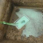
I pulled the board and holder out and rinsed them off in the sink. 🙁  I tried to decant the liquid without getting too much of the precipitate.  When I pulled the air stone out, it was heavily covered in the light green mush.  I started to rinse it out, and got a big wash of cloudy green in the sink.

Considering the possibility of acid depletion, I poured a very small portion (2 ml?) of the now very cloudy goo out into a small container, and added 5 drops of the 10M HCl I still had left from making the etchant.  It mostly cleared up to the good old beautiful clear green I’ve come to know and love.  Encouraged, I poured 50ml of the acid into the mess in the bottom of the tank.  It got a lot better, but as I stirred with a plastic stick (coffee pack holder from work), there was still a lot of precipitate in the bottom.  I poured the mostly clear liquid out, and put another 50ml of acid it.  The precipitate diminished until about gone.  I poured another 50ml of acid into the big jar with the early not-too-ugly liquid, and some residual cloudiness disappeared.
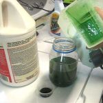
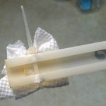
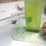
I swabbed the inside surfaces of the tank with the last 50ml addition, and it cleaned up nicely.  I saved that last 50ml and (sigh) washed out the tank and its badly dirtied base.  I scraped most of the bright green crystallized dried deposits off and into the etchant.  I poured all the etchant back into the tank, and it was once again beautiful clear green.  I guess I really should do a density test on it, and be more watchful of dropping acid levels.  For the record, I added a total of either 150 or 200ml of 10M acid (sorry!).
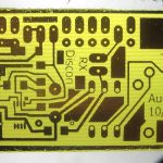
I put the board and holder back in, and when I fired up the air stone, the bubbles broke close to the surface like they always had.  I let it etch for about normal time.  It came out fairly OK, but there were a lot of pinholes I almost never see.  The text, which is often a good indicator (I think) of over etching (it gets skinnier) was only a little thinned.  Thoughts that the etchant is much more potent than previously weren’t supported by that.  There was also an issue with the ink jet printed artwork (!?$# Epson lost my custom settings!).  I have noticed that it was taking longer than I remembered to etch boards over the past few years.

Anyway, everything is nice and clean again  (though I do clean it every few years), and I think the etchant is up to par again.
Posted in Cupric Chloride Etchant | Tagged , , , , , , , , | 5 Comments

Custom map via google maps

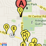
When I had to make a custom map with locations of many local restaurants marked for a square dance weekend we’re hosting, I got my feet wet with the excellent My Places on Google maps.  It’s easy to use, quite flexible and editable, and hosted for free by Google!  Couldn’t ask for much more.  This will definitely replace the DeLorme mapping tools I used to use.

If you’re logged into your Google account and go to maps.google.com and click the My Places button, you’ll see a Create Map button.  It’s pretty straightforward from there.  The simple toolbar lets you pan and zoom to wherever you want,  drop a map pin, or draw lines, routes, or shapes.

While there’s a nice selection of default map pin icons available, I needed a bunch of similar ones with unique labels that would print in black & white.  Googling numeric google map icons found these.  Google doesn’t host custom icons, instead requiring a URL to an image, so I copied them to my web host.  But when I tried to “Add an icon” it didn’t seem to work: the pin on the map disappeared, and “My icons” showed a broken image icon.  It looks like there’s a short delay to propagate the new icons and you have to refresh your map to see them.  After I made peace with that, making the map was a piece of cake.

The real URL of the map is long and ugly, so I sent a tinyurl of it to Lauren at work so she could capture an image to paste into a paper doc.  When she gently pointed out on the phone that I’d misspelled the name of a restaurant, a couple of clicks and edits and saying “refresh your browser” got me an “Oh, it’s OK now.”  Kewl.  We’ll put the (tiny) URL on the paper as well as a QR code, so if we need to make any other changes at least browser-equipped dancers will see the latest version.  That’s as close to updatable paper as we’ll get until we have those Harry Potter-style newspapers.

The bean counters have taken over at Google, so the google labs guys have lost a lot of their freedom to create new stuff.  While I don’t claim to know or understand it, I suspect the  financial incentive for Google to let this service exist is that while you can add your own layer of map pins and drawings, the base map on which they’re superimposed still has all the presumably paid-for business locations shown.  To this user at least, that seems like a fair tradeoff.

Posted in Miscellaneous | Tagged | 1 Comment

Make image link to video in WordPress

Sometimes I want a link to a small video clip, but the only way I’ve found directly in WordPress makes a text link to the clip.  I usually want a small image as the link – probably a frame from the clip.  Here’s the shortest way I’ve found to do that.  There’s probably a better way to do it, but I haven’t found it yet.  (WordPress has some direct support for YouTube embeds, but that plasters a big video window into the post.  There are also a bunch of plugins to handle video embeds, but I haven’t been moved to dig into them.)

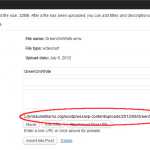
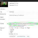
The first two things you need are the URL of an uploaded video and the image you want as a link.  You can upload the video to the WordPress Media Library with the regular Upload/Insert button.  I click Select Files, browse to my clip, and click Open.  Once it’s uploaded, the dialog you get gives the URL of the uploaded file in the Media Library (circled in red).  Copy that URL and click Save all changes (but not Insert into Post).  Presumably a link to a clip on some video file sharing service would work as well.  (Maybe they even have their own embed code?)

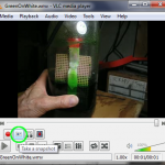
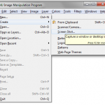
To get an image of a frame from the video, I often use the Take a Snapshot button in VLC (green circle).  You have to enable View->Advanced Controls for that button to show up.  In Windows I think VLC hides the snapshot in the My Pictures folder.  Probably even quicker, since I usually use gimp as my photo editor, is to use its built in screen (or window) snapshot grabber.

After you have the image you want as your link and the URL of the video, insert the image into your post with Upload/Insert as usual.  But before you click Insert into Post, change the link URL (green) to point to your clip.  Adding a Caption may make it more obvious that it’s a link to a clip.  Unfortunately the mouseover popup just shows the name of the image.

some alternate text

short clip

Here’s a link made using those steps.


Posted in WordPress | Tagged , , , | Leave a comment

Half-frame sunglasses for Prius

I love polarized sunglasses for driving.  Cutting glare from  the road, the rear window of the car in front of you, bodies of water etc is a great thing.  Unfortunately, the instrument displays in my Prius are also polarized, and are very hard to read with polarized sunglasses on.

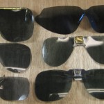
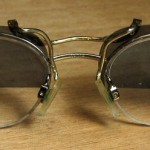
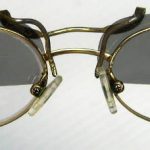
It finally occurred to me that I only need the polarized part for looking out the windshield.  The instruments are all below the windshield, so if I made something that was polarized on the top and not the bottom, I’d be able to see it all.  Fortunately, I’ve been hacking (and collecting) polarized clip-on sunglasses for years, so the old sunglasses box had a good stash of stuff to begin with.  I chose a pair with lenses riveted to a wire bridge that normally clips over the top of a plastic glasses frame.  (OK, probably from the 60s.)

Of course they had to be somehow custom fitted to the current glasses frame.  I bent the wires so they just clipped over the metal nose bridge of the glasses to hold them on.  Spreading the wires so they touched the metal lens frames would keep the sunglasses from sliding from side to side, but offered little resistance to sliding up and down or tilting.  By making the tops of the sunglass lenses 1/8″ or so higher than the glasses frame, I had room to epoxy two small scraps of plastic on the tops of those lenses, making a positive vertical stop and providing tilt-resistance to boot.  The extra also provided  a little additional darkening of the sky above the official field of view.  In retrospect, it could have been an even larger overlap.

After the glue dried and they’d been tweaked into their final resting position, I sat in the car with the still-full-size sunglasses on and drew a line with a Sharpie where I wanted the bottom edge of the lenses.  I tried to take into account sometimes wanting to tilt my head back if my neck was stiff and being willing to raise my head a little to see the instruments in return for not having an undarkened band above the instrument panel.  Then I cut a little below the line. 🙂

I tried them out and they delivered just what I wanted:  polarized view of the road and unobstructed view of the speedometer and nav screen.  (Yeah, yeah, they look kinda strange.  Oh well.)  I wish I’d thought of this years ago!

Update 8/21/18 (six years later!):  Those were my standard sunglasses for years after I made them up.  Then cataract surgery upset any stability I had in eyes/glasses/etc, and I went back to some old OTS polarized clipons for the one lensed “driving glasses” I’d made up.

Things stabilized somewhat with those glasses/sunglasses, but after a while, I realized once again that I had trouble reading instruments, including the GPS, due to the sunglasses.  Gee, if I only had some “bifocal” sunglasses that were clear on the bottom…

I dug the old half-frames out of the sunglasses box, and with no more than a little bending, they fit the new frames.  Looks like I’m back in business.  The fact that not doing anything silly like changing my eyeglass frame style over the years allowed this simple reuse is not lost on me. 🙂

It’s just kind of interesting that the basic need reasserted itself as things settled down with the new eyes/glasses.  I just ordered some new “full time” glasses (from Zenni) I should be able to wear both in the house and driving, and this reminder about the value of half frame sunglasses caused me to spring the extra $4 for polarized clipons fitted to those frames.  I’ll cut those down as soon as they get here.

Posted in Miscellaneous | Tagged , , , | 3 Comments

Amber’s PylePro amp repair

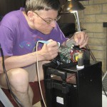
When Bobby told me the amp Amber uses for her dance classes was being flaky (often would cut out and needed a couple of whacks to get it playing again) I said I’d take a look at it.

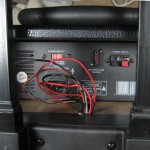
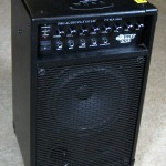
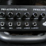
The PylePro PWMA-8601 is a pretty nice unit – 500W, AC or battery powered, lots of mixer inputs, an Ipod dock, wheels, normal and luggage-style handles, even built-in receiver for a wireless mic.  Whack it and it works – sounds like a classic loose connection.  How hard could that be?

A couple of machine screws on the sides release the amplifier, but before you can get it out you have to disconnect the Ipod dock on the top.  The two cables to it have nice little connectors, and soon the amp was free (but still tethered by several wires to the rest of the unit).

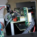
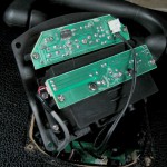
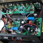
It looks nicely made, although the PCBs are just single sided.  The big board is the power amp (and power supply and battery charger).  All the front panel controls are on what I’ll call the mixer board.  Almost hidden below the mixer board is another board to which all the front panel jacks are connected.  Most of them are inputs, so I’ll call this the input board.

Outlined in red is the main signal cable from the mixer to the main amp.  In blue are the connections from the input board the the mixer.

Before I opened it up, I could reproduce the flaky behavior:  Lean it over one way and bump it and it cut out; lean it the other and whack it and it worked again.  Excellent.  While poking around inside, I noticed a very loose connector body on the main board.  Even before I knew it was in the main signal path it looked awfully suspicious.  But wiggle it as I might, I couldn’t get as much as a scratch out of the music playing through it.  For it to be that robust, I figured it was only mechanically loose, and still electrically connected.  I guessed the foil tracks had lifted off the PCB, removing much mechanical stability, but the pins were still soundly soldered to the tracks.  Clearly a failure waiting to happen, but apparently not the problem at hand.

As I poked around some more, I couldn’t get it to fail at all.  I got more and more aggressive poking and wiggling, but it still played perfectly.  Rats.  But all of a sudden, when I touched one wire, the audio cut out.  It was very sensitive, and if I very gently pushed it one way it would fail and work again when I pushed the other way.  I went through a couple of cycles, and it seemed to respond to my touches.  Then it wouldn’t fail again.  How could it have been so sensitive and then work perfectly?

The sensitive cable was the signals from the input board to the mixer, and I guessed it was unlikely that all the signals were affected.  I was only running signal through the audio in jack when it failed for a minute or so.  I emailed Amber asking whether the other jacks (like mic in) still worked when it was flaky.  If they did work, it pointed strongly to a flaky connection on the audio in wire in that inter-board cable.  (I couldn’t test that since I couldn’t make it fail any more.)  Unfortunately, she never used anything but the audio in jack, and couldn’t provide any more clues.  I wanted to chase that apparently temporarily sensitive wire some more.

I took the mixer and inputs boards out and looked for bad solder joints, etc.  I touched and wiggled and injected signals at various places in the path, and having found the exact wire that carries audio in from the input board to the mixer (leftmost red wire in picture above) pulled at it as aggressively as I dared, but never heard any evidence at all of flakiness.  Bummer.

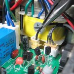
As long as I had most of it apart, I decided to pull the main amp board so I could try to do something about that loose connector body.  I was (pleasantly) surprised to see that the tracks were still firmly attached to the board, but the pins of the connector were no longer soldered to the pads.  I made a little clip to show how loose the connector was, and it pulled out in my hand.  OK – at least this is something specific I can fix.  (This isn’t the connector unplugging – it’s the connector body no longer attached to the PCB.)

I scraped the pins on the connector, wicked away the old solder, used my best flux and soldered it back in place.  Worked fine.  (Of course it also worked fine before I pulled it out.)

Was this the problem all along?  Those loose solder joints are completely consistent with the “whack it and it works” observation.  The other observation – that it would work for a while then quit – made Bobby very reasonably suspect overheating.  But that didn’t seem to be the case (and it wasn’t).  Of course it doesn’t take much heating to shift things the thousandth of an inch it takes to break a loose connection.  So this is also consistent with the “works a while and then quits” symptom.  Maybe that was it after all.

As I was putting it back together, I had a little trouble with the wires that go from the amp into the main housing.  (There’s the obvious red/black battery wires, and red/brown speaker wires.  But what the heck are the thin black zip cord and thin shielded cable?)  There’s a nice channel for the wires to lie in under the amp.  But you have to be careful to push the bulk of the wires back down their rabbit hole before you slide the amp all the way in.

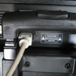
The amp is maybe 3/16″ narrower than the hole it lives in.  It turns out it matters how you align it.  The AC power cord is VERY close to one side of the handle, and if you don’t put the amp in flush with the left side (viewed from the front), you may not be able to get the plug in and out.

Since subtle heating was a known trigger for the problem, after it was back together I ran it (not real loud) for six hours or so and it didn’t fail.  I also used it for a couple of hours putting out a lot more sound for a basement dance, and it worked flawlessly then as well.  I’m guessing it’s fixed.

Posted in Miscellaneous | 1 Comment

Du(h)ll mower blade

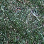
This picture could be right out of a textbook showing grass cut with a dull blade.  But it isn’t – it’s my lawn.  And it’s the same all over.

While I don’t know much about lawn care (or at least not much more than is forced down one’s throat during 3o-odd years of home ownership), I do recognize those tell-tale tips.  But it couldn’t be a dull blade:  I’m a little bit fussy about that, sharpening (and balancing) the blade a couple of times a season, and had just done so for this new mower a couple of cuts ago.

For the tips of the grass to be that badly butchered the blade would have to be really dull.  Like completely unsharpened.  Or I suppose it could be from the completely unsharpened back side of the blade if somebody were dumb enough to put the blade on backwards.  No, I couldn’t really have done that.  Could I?  <checks>  Oops.  Rats.

I didn’t notice ’til I was finished cutting this time.  The blade is now on the right way, and I fully expect the lawn will look better the next time I cut it.  I’ll post an update.  Duh.

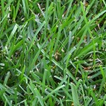
Update 7/22/12: Now that’s more like it.
Posted in Home Repair | 3 Comments

Making cupric chloride etchant from scratch

One of the goals of this project has been to come up with a recipe for making the etchant from scratch without need for tuning steps like titration or specific gravity measurement.  Just do these fairly painless steps and you’ll end up with a good batch that should run without touching it for a long time.  I’m willing to to the experiments and the tuning measurements and corrections to make sure it works.  Here’s a first attempt (corrected from an earlier version with bad data).

The approach is to use stranded copper wire, HCl and H2O2 as the initial oxidizer.  The question has been how much H2O2 to use.  Is it reasonable to put in enough to oxidize all the initial copper?  Is it so unstable that you couldn’t put it all in at the beginning and would have to put it in in batches?  Do you just put a little in to bootstrap the process and let the CuCl2 produced take over from there?  Certainly near the end there will be enough CuCl2 to finish up, but would the concentration be so low at the beginning that it would take a very long time?

We also need air continuously bubbling through the mixture, both for mechanical agitation and to oxidize the CuCl to CuCl2.  An aquarium pump, tubing, and air stone work well.

Our goal is to find how much of each reactant we need, with a little sanity checking on the amounts.

The basic chemistry

Unlike the reaction using CuCl2 which oxidizes the raw copper to Cu+, the basic initial copper oxidation reaction using H2O2 makes CuCl2 directly:

Cu + 2 HCl + H2O2 → CuCl2 + 2 H2O

If there isn’t enough H2O2 to completely oxidize all the copper (which is very much the case with our final recipe), whatever copper is left must be dissolved with CuCl2 –  the same way boards are etched:

Cu + CuCl2 → 2 CuCl

A second reaction that will be occurring simultaneously and continuously is normal conversion of the CuCl  to CuCl2 that happens during aeration:

4 CuCl + 4 HCl + O2 → 4 CuCl2 + 2 H2O

This takes a while, and will probably determine how long the whole etchant creation process takes.

OK – let’s shoot for 1 liter of finished etchant with 125-175 g/l Cu++ and ~2.5M acid content as may be inferred from the Seychell paper and the Chemcut paper.  (local copies – original links dead)

Copper

From the target concentration of say 150g/l Cu++  we’ll need 150g of Cu.  That’s 150/63.5=2.4 moles.  With my earlier determination that #12 wire is ~9g/ft (consistent with the 28Kg/Km from a wire table), we’ll need about 16 ft of #12 wire.  Stranded has more surface area, so that should dissolve faster.  One down.

Acid

The Cl will come from the acid.  To make one mole of CuCl2 we’ll need 2 x 35.5g = 71g Cl.  For our 2.4 moles, we’ll need 2.4 x 71=170g.  The pool acid I have is ~10M, or 10 x 35.5g=355g per liter.  To get 170g of Cl, we’ll consume 0.5l of acid.  Two down.

We also know we need to end up with a bath that’s ~2.5M.  Starting with 10M acid, we need 0.25l of concentrated acid in a liter of solution to be 2.5M.  If we add an additional 0.25l of acid to the initial soup that should cover it.  So we’ll need a total of 0.75l of concentrated acid.  Not much room left for peroxide!  (We might consider adding at least some of that last 0.25l of acid at the end to reduce fuming early in the reaction.)
H2O2

Is it even feasible to put enough H2O2 into the starting solution to react with all the copper?  From the original equation Cu + 2 HCl + H2O2 → CuCl2 + 2 H2O, we need 2.4 moles of H2O2 to react with our 2.4 moles of Cu.

The 3% peroxide is mostly water, so 1 l is 1000g.  If 3% of that is H2O2, we have 30 g/l.  With MW of 34, that’s about 0.9M.  So to get our 2.4 moles, we’d need 2.6l of peroxide.  No way!  We only have 1 l for all the initial reactants, and we’ve already spent 0.75l on acid.  We only have room for 0.25l – only 10% of what we need to react with all the copper.  What to do?

If we don’t want to have to evaporate the solution down and don’t want to have to find higher concentration H2O2, about all we can do is run the reaction, burn through all the H2O2  and hope the resulting CuCl2 concentration is high enough to dissolve the rest of the copper in a reasonable amount of time.  (The reaction would speed up over time as the concentration increased, but the continuous need for oxidation of CuCl to CuCl2 via aeration would probably limit the rate of the reaction.)  If we put more H2O2 in, we could initially dissolve more copper, but that blows all the other calculations.  We’d end up with more liquid, so our 150g Cu would give a lower concentration, and it would also put us below our target 2.5M acid concentration.

A quick check at Amazon found 4 oz of “35% food grade” H2O2 for $9 (plus shipping).  That’s ~0.125l.  Just to run the numbers:  With a density of 1.13g/ml (looked up here), one liter of that stuff would be 1130g.  If 35% of that were H2O2, that would be 395g, or with MW of 34, 11.6M.  To get our 2.4moles, we’d need about 0.2l – ~two bottles.  Wow – we do have room for that.  I guess I’ll have to look for a local source.

So a very interesting race would be to run two batches, one with 0.25l of 3%, the other with 0.2l of 35% and see which one takes longer to finish.

So our first guess for the recipe (which might take a long time to run to completion):
16′ stripped #12 wire
750 ml 10M HCl
250 ml 3% H2O2   (250 ml of 6% should make it all go faster if you can find it)

WARNING!  Don’t use the recipe below – at least not in one step!  See the very unpleasant experiences in this post.

Or if we can find 35% H2O2:
16′ stripped #12 wire
750 ml 10M HCl
200 ml 35% H2O2
50 ml water

Reaction vessel

We need room for a liter of liquid, a place to put the wire, room for an air stone to make bubbles, and some headroom above the liquid.  Metal containers are out.  How about a 2l pop bottle with the top cut off?

It turns out splashing of etchant while bubbling is an issue.  With air constantly being pumped in we obviously can’t have a sealed container, so we need a way to contain/redirect the tiny aerosol droplets.

Funnel defeats splash

One interesting mechanism is to put a funnel (plastic, of course, and larger diameter than the mouth of the container) loosely in the top of the container.  Air can escape around the edges easily.  The hole in the stem provides a fine way to run the air tube in.  Droplets that hit the funnel and coalesce into larger drops will run down the outside of the funnel (and down the air hose) back into the bath – perfect!

To provide an additional level of protection, a disk of the clear plastic from clamshell packaging almost the inside diameter of the bottle supported maybe an inch above the top of the liquid should catch the great majority of droplets.  Angling the disk would give the drops a preferred direction to drain off.

We still need a way to support the wire in the middle of the liquid so the air bubbles are constantly streaming past it.  I had good luck previously with a little hammock or sling made out of the coarse plastic backing fabric used for counted cross stitch.  It’s spent maybe 2 weeks in the acid so far making 2 batches of etchant, and seems still in fine shape.
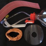
Here are the parts I came up with.  I was pleased with making the “funnel” out of the top of a second bottle (so it would be big enough to not fall in).  Its screw threads provide a great way to mount both a hanger for the sling that holds the copper and a hold-down for the air stones.  (The yellow stone is stained from previous duty in my etch tank before being replaced with a bigger stone.)

The orange hook that holds the copper sling is cut from a heavy duty jug (HDPE ) from laundry detergent.  A hole in it just fits the neck of the “funnel”, and the screw top holds it on.  Heating it helped the bends stay how I want them.
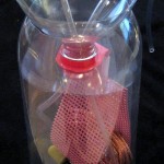
I heated and bent a piece of the coffee packet holder plastic I stocked up on from work to hold the air stones and fitted it to clamp to the orange piece.  The clear circle “splash guard” (cut from the bottle that gave up its top for the funnel) also fits over the neck of the “funnel” and is also clamped in place by the screw top.  Nothing magic about any of this – it was just from scrap I had on hand.  Here’s the whole reaction vessel.

Air pump

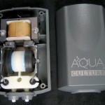
So far I’ve used the cheapest air pump I could find, sized for 5-15 gal tanks.  The last batch I made took a long time to aerate the CuCl to CuCl2, and I’m guessing more air would be better/faster.  I hope it will make for more uniform and quicker etching, as well.  So I got the next size up cheap air pump at Walmart – for 20-60 gal tanks.  This Aqua Culture MK-1504 says it pumps up to 2800 cc/min.

I was surprised when I opened it that it had two output nipples (mostly because I hadn’t looked at the picture on the box that showed that feature clearly).  Okaaay – will I have to seal one off if I only want to use one?  Putting fingers over the outputs while it was running indicated pressure on each side even if the other side was open.  So it’s not just a tee on the inside.  Are there really two pumps?  <takes pump apart> Answer: yes.  And that means if I want the full output of the pump, I’ll need to hook up both hoses.  A couple of quickie tests with a stopwatch and inverted glasses in a sink full of water proved that and also showed even the small stones didn’t significantly decrease air flow.  OK, I can deal with two hoses.

Using air stones makes lots of tiny bubbles to maximize the bubble surface area in hopes of efficient reaction.  I’ve had trouble with the air stone not staying on the bottom where I want it.  (I guess the “air” part won out over the “stone” part.)  Heat from a propane torch made segments of a piece of the coffee holder plastic very floppy and easy to form into a crude hold-down for the two stones.

The question of how temperature affects the reaction is interesting.  An aquarium heater (maybe with the thermostat hacked for higher temps) might be appropriate both for making the etchant and for faster etching, but I don’t have one yet.  To be determined…

Show time!

The peroxide I had is more than a year old, I don’t know how fast it decomposes, I don’t have any way to test it, and I need all the strength I can get since I can only put in 1/10 as much as I’d like.  I got a fresh bottle.  (I have an idea for a yeast-based vaguely quantitative H2O2 test approach.)

The 16 feet of wire when stripped had a mass of 147.2g according to my cheap digital scale.  Close enough to the 150g I was shooting for.

I don’t expect problems with the pop bottle, but prudence says a containment vessel just might save me from an unpleasant experience with a liter of acid on the floor.  A cut down gallon HDPE jug should be fine.

A final test fitting of all the parts and I was ready to go.  Peroxide in.  Acid in.  Smell those fumes!  Lower the guts into the bottle.  The slightly yellowish clear liquid started to turn green within seconds.

I took it down where the etching tank normally lives in the basement and connected and fired up the pump.  In a minute or two the fumes were so strong it was clear this wasn’t a good plan.  I took it outside (no bubbles) while I invented plan B.

There’s no good place for it outside, so the garage is the next best place.  I needed a way to hang the pump, and it would be convenient to have it all one piece so it could be moved easily.  A scrap of 1/2″ EMT with the end squashed and a scrap of plywood quickly became the platform.  Crude, but effective.

With the garage door open it should be fine.  At night when both cars are inside, I’ll probably leave it just outside, at least for the first few days.  The fumes should decrease as the chlorine gets locked up to the copper, and then I hope to leave it in with the cars and the door closed over night.

In the half hour or whatever it took to bolt the conduit to the plywood, the solution had turned very dark green (even without bubble agitation).  Here it is boldly posing naked of its containment vessel.  The baggie in the top is protection from fumes for a chunk of metal weighting the top down.

The bubbles are not at all the tiny ones I expected, and look much more like what would come out of raw tubing ends.  I gingerly pulled the innards (all conveniently attached to the funnel top) out just enough to see the stones.  They were both still there, and seemed to behave normally.  Maybe there’s just so much air in the small space around the small stones that it coalesces into bigger bubbles before it gets to the surface.  Too bad – that may slow down the CuCl -> CuCl2 processing.

Anyway, it’s off and running as of ~4PM 6/27.  I’ll keep an eye on it and report from time to time.

Update 2:30P 6/28:  The liquid is very dirty brown – it’s clearly in the “lots of cuprous” stage waiting for /throttled by aeration oxidation of Cuto Cu++ .  Curious how much of the copper was gone, I gingerly lifted the guts – top funnel, splash disk, copper hanger, and air stones out of the outer bottle.  When I put a drop of the liquid on a piece of white plastic, it looked like the 20g/l picture from Seychell’s white card test pictures.

Ignoring the little incident of the wet splash disk (which is obviously smaller than the hole in the top of the bottle) snapping out at the very end and spraying fine droplets of acid in my face and eyes (mostly only the right eye), it was clear that quite a bit of the copper was gone.  It’s hard to be very quantitative (especially with tears streaming out of one eye), but it looks like it’s more than half gone.

I watched as I lowered the stones back in, and there were clearly lots of bubbles from all over both of them.  Maybe a pair of larger stones would spread the small bubbles out better.  But overall the reaction is going well – maybe more quickly than I feared.  Helping speed things along is that it’s hot out – 90F yesterday and near 100F today.  That should be speedier than the ~70F in the basement for the previous batch, but I don’t know how much.

(Yes, I did go in and wash my face and flush my eye – even before I got the camera out.)

Update 7:30A 6/29:  I was going to take a picture of the copper – but (as of about 40 hours into the reaction) it’s all gone!  The white card test shows the bath is still 10-20 g/l Cu+ , but with the bigger pump, that should clear up fairly quickly.  I’ll start checking it more frequently now.

I think the splash disk is very effective at keeping the aerosol in check.  Some still gets above the disk, as evidenced by droplets on the inside of the top of the bottle, but I’m sure a lot more would get up there without the disk.  (I suspect the droplets are green despite coming from murky brown liquid below because their large surface area allows them to have their Cu+ oxidized quickly to Cu++ by exposure to air.)

Unfortunately, the disk is a significant pain to deal with.  Since it’s considerably larger than the hole in the top of the bottle, it must be bent to get it in and to get it out.  When it’s clean (like loading the stuff in the first time) that’s not a problem – the disk is pretty flexible, and squishing the bottle a little makes its opening oval to more easily accept the disk.  But when you try to pull the innards out – whether to try to take a picture for documenting how much copper is left or at the end of the run when you’re taking it all apart, having a good-sized piece of springy plastic wet with dirty acid makes the job messy, if not dangerous.

I’m considering skipping the disk for the next batch.  As an additional layer of protection against the aerosol, I think something like a cylindrical skirt of kleenex or paper towel say hanging down from the top of the funnel, long enough to touch the body of the bottle would help a lot.  Another implementation would be a band wrapped around the waist at the top of the bottle, possibly cinched lightly with a string or barely stretched rubber band and touching both top of funnel and outside of bottle.  Attaching it to the funnel would make it more convenient when taking the innards out for mid-reaction observation.

That idea comes from a kleenex I’ve been plopping loosely over the top of my etch tank for some time.  While I have a splash guard in the top of the tank, the kleenex catches anything that gets past the guard.  The green stains indicate that it must be catching stuff.  Really simple, but I think it helps quite a bit.

Update 11:30A 6/29:  Still dirty brown (10-20g/l Cu+ ).  But in looking at it, if I slosh the liquid over the white plastic air stone hold-down, I can see the color pretty well without extracting a drop to put on a card.  Here’s a little clip.  This suggests that including a piece of white plastic near the outside of a clear etch bath container could provide a very simple way to observe the color of the solution for visually estimating the cuprous concentration (based on the white card photos).

Update 10:30A 6/30:  It’s done!  I think it’s a little lighter green than my current working batch, but I haven’t done specific gravity and acid concentration tests yet to verify that it’s all in range.  Again, here’s a little clip of the “slosh it over white plastic” test.  I’m really pretty excited about the simple inclusion of a bit of white plastic providing a very serviceable way of telling when aeration is complete.

As a separate question, I wonder if bubbling all that air through the solution evaporates some of it.  It seems plausible that the bubbles would end up pretty well saturated with whatever vapor the liquid gave off, and would carry that vapor away in the stream of air created by the burst bubbles.

If that is the case, there are two important implications:
a)  A significant part of the decrease in volume of my etch bath I notice over time might be due to water loss from aeration.  If that’s that case, I should be adding water to make up that part of the loss.  (Certainly some of the loss is liquid droplets wetting the boards and board holders that is forever lost as I rinse those things off.)
b)  Evaporating some the liquid in a new batch being made might be practical.  Since I’m very short on volume to put enough (weak 3%) peroxide in, any evaporation I could get, either as a byproduct of the aeration needed to make the bath or in additional aeration after the solution turns clear green would give me room for more peroxide, speeding up the first phase of the reaction.  (Hmm – I suppose if I have to add a step to the recipe to  aerate for several additional days to reduce the volume of liquid down to the target, the benefit of “getting to green” quicker by means of the extra peroxide doesn’t help much.)

In any event, I should run a test – probably just with water – to see what the rate of loss is due to aeration.  I’d guess it will be pump and ambient humidity dependent.

Update 7/21/12: Finally got around to testing that batch.  I made up some 1.0 M NaOH,

Ready to go

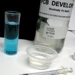
saving 20 ml or so for this and future use and diluting the rest to 1% for PCB developer.  I refound the nice 1 ml syringe I’d used before and used it to put one ml of the new etchant in ~25 ml hot water.  Then I used it to slowly add the 1 M NaOH – stirring constantly – until it just started to be cloudy.  It took 2.9 ml of NaOH, so the acid in the etchant was about 2.9 M.  That’s a little higher than I expected, but completely acceptable.

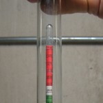
Using an automotive battery hydrometer and extrapolating past the calibrated scale, it looks like the specific gravity is ~1.31.  That’s right around the optimum density according to Seychell’s observations.

Just for fun, after I pulled out the air stones etc I marked the level of etchant in the pop bottle reaction vessel.  After I’d stored the etchant in another container, I filled the pop bottle to that mark.  It took about 1.055 l.  I wouldn’t have guessed I blew the initial liquid measurements by that much, though I suppose adding all that copper might have increased the volume a little.  But it’s quite close.

Given all that, I’d have to say the recipe I used was a complete success!

Posted in Cupric Chloride Etchant | 4 Comments

Boards ordered from Seeed for recording preamp!

I’m getting really close to my goal of having a solid, standardized, manufacturable square dance recording device.  I just sent out the Gerber files to have the first run of circuit boards made!  The earliest notes I can find about this project were from March 2005, so I’ve been working on it for a long time.

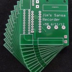
I’d planned to make the PCBs myself, but when I ran across an offer for ten 5 x 5 cm double side boards with plated through holes and silk screen for $9.90 from SeeedStudio, it was too good to refuse.  The existing boards were about 5×6, so I had to move a bunch of stuff around on the board to fit the smaller outline.  By the time I was done, I wanted some warm fuzzies that I hadn’t messed up, so (working on a copy of the layout!) I made a couple of minor hacks (like adding pads for jumpers for the few traces that were on the bottom side) and made up a single sided board.

I used my now standard ink-jet-printed transparency artwork and pre-sensitized boards, but must have been distracted:  I skipped the development step, and put the board directly from the exposure holder into the etch bath!  I’ve never done that before.  Fortunately, the resist is developed away in the exposed parts, so the whole resist layer was intact for the minute or two it spent in the etchant before I realized what I’d done.  I pulled it out, rinsed it off well, developed it, and etched it.  It came out about perfect, as always, despite the missteps.

Unfortunately, populating the board didn’t go as well.  I used solder paste and soldered by hand.  I think there’s spatter from the solder paste if it heats up too fast (which is easy to do with an iron), and I ended up with shorts to traces passing under a couple of resistors and so much trouble with the (0.5mm pitch) 2167 that I had to take it off with a hot air gun and put it back on from scratch.  I ended up scrapping that board – which I’ve never had to do before.

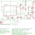
But as a result I cleaned up the layout some – moving things so I had only one trace instead of two going under one resistor that had shorts under it, increasing clearances in several places.  Oh yeah – and fixed an error that reversed the power supply leads to the Sansa!  It was connected that way for a couple of minutes while I tried to figure out why it wouldn’t light up.  When I noticed it was also getting hot I pulled the battery until I figured what I’d done.  Oops.  But in an incredible stroke of good luck – and robust engineering from the Sansa designers – it survived apparently unscathed, and seems to still work fine.

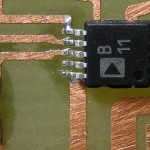
But I’d made several more changes, and still wanted warm fuzzies on the new layout before I sent the files out to the board house.  So I made up one more single sided version of the board, this time being less generous with the solder paste, especially on the 2167, and reflowing it instead of doing it by hand.  MUCH better.  The one simple bridge on the 2167 came right off with some solder wick.  (It’s really small – there’s a 1206 resistor just for scale.  The traces immediately off the 2167 pins are 10 mils.)

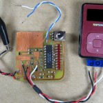
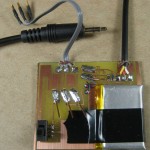
I wanted to test the electronics without having to completely assemble everything first, and since I’ll be building a bunch of these, I made up some test bits I could tack solder on for initial testing.  I expect I’ll use the audio in, battery/power supply leads and Sansa hook up with each board I as I test it.  And yes – it all worked first try this time.

Update 8/26/12: Since I’m going to have to test quite a few of these things, a test jig is a good idea.  Tack soldering leads on works, but I’d often have to use solder wick to clean out holes even if I didn’t actually solder wires into them.

So I made up a little “bed of nails” tester.  I was too impatient and cheap to order pogo pins to do it the right way, so I just soldered some pieces of the solid #20 hardish copper wire from telephone (outdoor?) station wire I also use as the connections and mounting pins for the Sansas at a shallow angle as slightly spring loaded contacts.  They’re maybe 1/4″ above the board at the free end where they touch the holes in the board under test.  I used the original board layout in Eagle to locate the contact points – the centers of the 3 Sansa pin holes and the 2 holes for the audio input cable – left small circles on the tester board in those locations, and laid out small rectangular blocks to solder the wires to that pointed them to those circles.  From the almost straight-down perspective of the picture, you can see one of the circles a little below the tip of the upper right hand pin/wire; the lower left hand one’s tip is directly above its circle.  I taped an old Sansa battery (I have lots!) to the board so it can power the Sansa and electronics without bothering with a power supply.  I put a switch in series with it because it seemed like a good idea.  🙂

The external connections to the recorder board under test are the 3 Sansa pins, the 2 leads for the audio cable, and the 2 leads for the battery.  But since the battery leads are also wired directly to the Sansa, there was no need for additional pins to contact them.

The 3 Sansa leads are brought out to female pins from RS-232 connectors that fit (poorly) either the 0.025″ pins from one of the early Sansa like the one pictured or the #20 wire pins of a Sansa built to solder to the board.  The latter allows testing with the actual Sansa I’m about to use before soldering it in place.

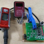
Since my usual audio test source is an old Iriver (that used to be a mainstay recorder!), I needed a 3.5mm male plug to connect to it.  Following my preference for pig tail leads, that’s what comes off the tester board.  But because I needed to mix the two stereo output channels of the Iriver, I put a couple of 22Ω resistors on the tester board to avoid connecting the two outputs directly together.  Here’s a pic of a board ready to test.  Yeah, I have to bend the “springy” wires back up maybe every other time I use it, but it’s quick and it works.

Getting ready to send out for boards

Trying to get all the information needed by a board house – silk screens, solder masks, board outlines, in addition to the basic traces and pads and vias –  in the right format is a lot more complicated than making up B/W artwork for my simple single sided boards.  Fortunately, Seeed’s Fusion cheap PCB service has been around for a while, and in addition to their page of instructions on how to submit your board files, there’s an FAQ, an independently contributed set of more detailed instructions, and a forum where many of the beginner questions are posted and (mostly) answered.

Seeed provides an Eagle design rule file that knows stuff like minimum trace widths and various clearances, so you can run a Design Rule Check in Eagle to catch some kinds of errors.  It also provides a CAM processing file that lets Eagle produce Gerber files in the required  RS274x format.  And someone highly recommended checking the resulting Gerber files with a Gerber viewer like the open source gerbv, so I have that useful tool as well.

After a LOT of iterations through those tools, checking the forum, tweaking the board design, and slowly becoming more familiar with how it all fit together, I was ready to start the two-step order process.  I placed an online order for one instance of the PCB service for 10 5×5 boards with options yada, yada.  It came to $14 with shipping (from China).  I got an email back immediately with my order number.  Then I sent an email with my Gerbers, referencing my order number.

Now I just sit back and wait.  Oh, and make up a Bill Of Materials.  And make sure I actually have enough parts to build these things up.  And finalize the mechanical mounting details, and finish putting the two boards lying around with temporary leads flapping into their permanent cases.  And start modifying the pile of Sansas I’ve found on Ebay.  Oh yeah, and figure out what to do about the Rockbox firmware bricking V2 Sansa Clips.  (Clip Plus and V1 Clips seem to be OK.)  So much for sitting back…

The Sansa Clip V2 problem

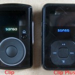
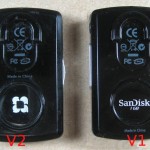
There are 3 variants of the Sansa recorders in play.  My original line-in hack was to the “Clip Plus”.  When I needed some more, I found lots of the model called “Clip” on Ebay, and they seemed to work.  In fact the mechanical modification is slightly easier with the Clip.  But as we’re modifying the firmware, the more subtle distinction between Clip Version 1 and Version 2 becomes important.  The code is different for the two.  Fortunately, they’re easy to tell apart just by looking at the back.

After I had all my code tweaks in place, I thought all I’d have to do was build for the correct target hardware.  There’s even a configure script that sets the appropriate defines.  So I built for a ClipPlus, ClipV1, and ClipV2.

The first time I loaded my custom version on a V2, it bricked the device.  I grumbled, and the next one I picked up was a V1, and it worked fine.  But when the second V2 I flashed didn’t work right (functioned, but was not recognized over USB), I started looking into it.  It looks like (at least some) versions of Rockbox at least some times brick V2s.  Not good – I have several V2s in my stash.

Fortunately, there are (rather arcane) instructions on how to unbrick a V2 by opening it up, and booting it from cold while 2 test points are jumpered.  This brings the device to a special ‘recovery’ mode, where at least it will boot and it will show up as a storage device via USB.  You can then dd an image of the original firmware in from a Unix box, and at least have it running the original firmware.  I haven’t tried that yet.  I did the boot-while-shorting-2-pads dance and brought a bricked V2 back from the dead.  Many thanks to the Rockbox community for making info like this available!

I also don’t know whether the version I’m building my custom on top of is one that doesn’t play well with V2s.  Maybe if I just redo all my tweaks on top of a later version of Rockbox it will work.  Much more to discover.

V2 update 8/21/12:  Rockbox code used to be managed under svn, and I’d gotten to the point that I could grab the latest code base from that system.  Between the code I’d modified and made peace with that worked for Clip V1 and ClipPlus and now, they moved to git.  Nothing against git (and I think I might even have made a little git repository for something once upon a time), but I’m not familiar with it, so it took a couple of tries downloading various clients until I could actually get current Rockbox code.  They also changed (at least the internal) version numbering, so all I can report is that what I grabbed seems to be “b61b14f”.  And for reasons I’m sure some of the devs felt were good, some of the code was restructured so some of my changes were no longer in the files they used to be in.  But grep is my friend, and I eventually found where to put all my hacks.  (Hmm – it’s not clear whether I updated the “mychanges.txt” file that listed the changes and filenames.)

The good news is that after I put my changes in and built for V2, the code loaded into a Sansa V2 and worked.  I think I’ve put it in at least two V2 units with no problems.  So whatever the ‘brick’ problem was, at least this code version seems to have fixed it.  I am however now pretty religious about upgrading any new Sansa to the very latest Sansa firmware before installing Rockbox, and always using the latest Rockbox installer.

Of course it would be nice for all the images I install to be built from the same code base.  I tried rebuilding V1 and ClipPlus with the new code (it’s just a build flag), but ran into some kind of problem.  I should go back and address that.  But worst case I have my old V1/Plus image and the new working V2 image.

Anyway, it’s nice that I don’t have to try to sell off all those V2s and start asking questions to identify V1s before I make Ebay bids.

Bill Of Materials

1    PCB (board house or homebrew)
1    SSM2167 (mini-SO-10)
1    LM3914 (PDIP 18)
10 LEDs (1206 SMT or 2x5LED HP strip from ElecGoldmine)
3   10uF SMT cap, pref 1206
2   1uf SMT cap, 1206
1   1.5K resistor 1206
1   2.2K resistor 1206
1   2.7K resistor 1206
2   4.7K resistor 1206
1   6.8K resistor 1206
1   22K resistor 1206
1   33K resistor 1206
1   68K resistor 1206
1   FDV30 N-chan IGFET SOT-23
1   10K audio taper min pot Digikey P3D4503
1   RCA male cable 18-24″
1   plastic case  2.5″ x 3.5″ like Container Store 10054865
1   850 mA-hr LiPo battery like SparkFun PRT-00341
Servo tape, epoxy, solder paste and other assembly necessities
1   modified Sansa Clip or ClipPlus 1GB or larger
1   small PCB for mounting external leads to Sansa
2  thick 4-40 nuts with captive lock washer
2  4-40 x 3/16+ flat head machine screws
1   USB mini-B 5-pos cable with small connector body
1   copy Jim’s user manual
1   copy Jim’s custom Rockbox software (currently based on 31180)
plus whatever else I’ve missed…

FinalSchematicAnd just for reference, here’s what I think is the final schematic:


Got boards!

The boards just came today 6/27, about 15 days from when I sent the order in.  Not bad.  And there were 11 boards instead of 10.  Can’t ask for more.

They look great!  Even if I went to the trouble of figuring out how to reliably make double sided boards (and stocked double sided board material, etc) these are way nicer than anything I could make.  The silk screen on the back will show through the translucent case, and on the front it labels (if tinily) the level control and even has interlocking squares.

I guess I oughta stop oohing and aahing and build one to see if it actually works 🙂

Update 8/21/12: The boards seem to work fine.  I’ve made up 4 of them so far. The only problem I’ve found is that I failed to stop the solder mask in two spots where I solder the case of the level pot to the board.  There was never a problem for my simple single sided no-solder-mask homebrew boards – I could solder anyplace I wanted!

Here’s the soldered place and the scraped off mask.  Not a big deal to fix – just a minute or so with an Xacto knife.

I’ve reflowed all four boards so far, and that has worked well.  But I still have to be careful of solder balls that form when I put too much solder paste on.  Balls this size wouldn’t be a problem for most boards, but with that 0.5mm pitch 2167, these balls could cause trouble.  I’ve added an inspection step to look for and knock off these little buggers.

Here’s one of the production models made up.  I’ve actually delivered the first one (to Ron Hazslip – yay!); this is number 2.  The only bit missing from this one is a shield/cover made from clear clamshell packaging plastic over the battery and visible parts of the PCB.  I’ve started to make a template for that, but it doesn’t fit very well yet.

While the board is laid out to accept either 1206 SMT LEDs or the thru-hole 5-LED blocks from Electronic Goldmine, all 4 so far have the thru-hole ones.  They’re mounted funnywise at an angle to make them more visible from the side.  Looking down from the top they’re still quite visible, but this way there’s enough light going about parallel to the board that you can see them acceptably through a hole cut in the side of the case.  This makes it possible to check that the LEDs are bouncing without having to go up to the caller’s table and look down on the recorder.  A nice feature that pretty much works as designed.

Where they went

I started to lose track of how many of these things I’d made up, so here’s a place to store the history.

I started with 3 newish prototypes in my recorder bag.

* Seeed board #1 went to Ron H at Romney weekend 8/12.
* #2 went to Tony Oxendine 8/22/12.
* one of my newish prototypes (single sided test version of Seeed layout) went to Noah Siegmann 8/22/12.  I need to make a Seeed board up to replace it.
* #3 will go to Tom Miller probably delivered at Turkey Run Adv weekend
* electronics are done and tested for # 4, 5, and 6 – one Sansa modified so far

Some mechanical details

Mounting the Sansa involves some manual work.  The initial modification to the device includes epoxying a small PCB inside that provides a sturdy place to solder the 3 heavy wires coming out of the back of the case that do double duty holding the bottom of the Sansa to the board in addition to providing electrical connections.  There’s a little spacer to hold the lower end the right distance from the PCB.  Looks like I haven’t rounded off the corner of this board yet.

The main mechanical mounting is two 4-40 machine screws near the top of the PCB.  Nuts are epoxied to the back of the case (after sanding to provide some “tooth” – I seem to have gone overboard on this one).  The alignment of the nuts is assured by putting the screws thru the holes, tightening the nuts on and clamping the whole thing together as the sparse initial epoxy sets.  After that it comes back apart and I build up a generous fillet of epoxy around each nut.  It turns out 1/4″ screws are too long and 3/16″ are too short, so I have to run a nut on a 1/4″ screw, grind a few threads off the end, and reform the threads as I take the nut back off.  Not too hard, but it’s an extra couple of steps for each one I make.

I cut the plastic shaft of the level adjust pot down so the case closes comfortably.  Not using a knob provides a little extra protection for the pot from being bumped and misadjusted.  To provide an index line, I saw a small slot with an Xacto saw and fill it with white-out.  Some black magic marker on the top helps the contrast.

You can see the hot melt strain relief for the coax input cable in pictures 2 sections above.  Cutting the little edge-view window for watching the LEDs while the recorder is on the table is a slow, careful exercise with an Xacto knife.  I’ve tried roughing it out with a cutter and a saw blade on a Dremel, but there was no major time/effort savings.  Hmm – I wonder if a jewelers saw would help on the rough cut?  I’ll try that next time.  “Servo tape” sticks the parts in the case well, but allows disassembly if it’s really needed.  There’s even marking for where the tape goes in the silk screen on the back.

The last mechanical detail (after putting the annoying warning sticker on the LiPo) is a thin clear plastic cover to keep stuff out of the PCB, be the glazing for the edge window, and provide a little extra protection for the battery.  (Yeah, yeah, it’s a cell, not a battery.)  I’ve tweaked the template so it pretty much fits first try when I cut one out.  And I even scanned the template to a soft copy so if that little beat up bit of card stock gets lost I can still make the plastic covers.

Posted in PCB Etching, Recording preamp/limiter | 2 Comments

@#$%^& WordPress ate my post!

I finally had a candidate board layout for sending to a board house to start production of my recording preamps.  There were quite a few changes, so to test the layout I etched one single sided, with a few minor hacks to deal with that.  I populated it and it didn’t work right.  The high and low reference voltages for the 3914 that displays the voltage on the AGC averaging cap were off.  Did I really blow the values in the divider chains that determined those values?  Troubleshooting time.

Calculating the resistors for a 3914 from the datasheet is doable, but I’ve already done it and even carefully recorded both the technical details and design decisions here in these Project Notes just so I wouldn’t ever have to do it from scratch again.  <searches for “3914”>  It’s not there!  WTH?

<searches local disk>  I found the .png exports of the little schematics I did in Eagle for the explanation.  I’m positive I wrote this up and posted it here.  What’s going on?

Searching posts mentioning 3914, I found a note in this post about WordPress losing some updates.  I’d had an edit window open longer than they support, and when I tried to save, it discarded my latest work and sent me to a login screen.  Since I’d been inactive for a while before entering the last paragraphs, the autosave feature didn’t kick in to help.  Not that it would have helped much:  One other time I tried to use an autosaved version and was completely stymied by the inscrutable user interface to restoring old versions.  Since it only saves one old version, in stumbling around trying to use the saved one I lost it.  Your autosave feature isn’t very useful if a motivated user can’t figure out how to use it, WordPress!

I was about to go through the 3914 resistor calculations again, and document it again, when I remembered I’d done backups of the database.  Might the lost details still be in the backup? I found the 12MB file in the nicely labeled _db_backups directory and pulled it down.  Doing a string search in that .sql file, I found the writeup!  It was unformatted, ugly, and difficult to read, but it was there.  Worst case, I can resurrect the details from there, easing the task of rewriting it all.

But it’s a backup.  Can I get the system to do it for me?  How do you restore a backup?  Ugh – if I restore that one, I lose all the recent stuff.  OK, I could do a new backup, renaming and keeping track of the files, get the old stuff back, save it somehow, and restore the new backup to get back where I started.  Unless of course something went wrong, which seemed all too likely.

In googling how to restore, someone made the clever suggestion of making a completely separate second WordPress installation and restoring to that one, leaving the good instance safe and sound.  So I did that, with the new one in the wordpress2 directory paralleling the original wordpress directory.  I even succeeded in importing the backup database, though I had to do it from a file on my PC rather than on the web host.  And I could see the missing writeup!

But it was worse than I expected:  It wasn’t just a couple of paragraphs that were missing – it was a whole post!  I can’t believe I would have intentionally deleted it, so I have no idea what happened.  But if there was one post missing, how many more had disappeared?  There’s direct SQL access to databases from by MyPhpAdmin (after you find it, which always takes several tries.  Howto: Log in, My Account, Web Hosting, my hosting, Databases, My SQL, choose database, log in to that database, expand the database in the left hand pane, choose a table.)  Using Browse Distinct Entries on the post_title field of the wp_posts table I did queries on both new and old databases to get sorted listings of all the post titles.  There were 499 in the old db, 735 in the new.  When I diffed the lists, to my relief there was only one title in the old list that wasn’t in the new list.  (And that was the one with the 3914 details.)  Whew!

OK there’s only one post to deal with.  How to restore a single post?

I could use SQL from MyPhpAdmin to export a row from any table in one database, even formatting it as an Insert command so it could be applied to another.  But while there were a few obvious relations, I don’t understand the database structure well enough to be positive I could hack everything in seamlessly.  Rats.

So I tried to log in to the admin page, edit the old post, copy the content – probably from the HTML view – and paste it into a new post in the good database.  Nope.  I couldn’t log into the wordpress2 instance.  No matter what I did, it always logged me into the original instance.  Rats.

So I just viewed the post from the old imported database, highlighted and copied all the text in the browser, started a new post in the good database, and pasted the text in.  It lost italics, links, heading formatting, and of course all the pictures.  So I painstakingly restored all that stuff manually.  The pictures were still there, but hard to find.  I found that by hovering over a picture in the old post, I could see the file name.  Searching for that name (or a substring) made it quite quick to find the pictures as I was putting them back in.  There were a couple of pictures with 2 instances in the media library – maybe I’d updated a picture and uploaded a new version?  I didn’t try to make sure I got the latest versions.  But I did get it all done.

And finally I could read the note, relearn how the resistor calcs worked, and was able to finish troubleshooting and repairing the board that started the whole thing.  Ugh.

Posted in WordPress | Leave a comment