Repairing Melnor Time-a-matic

Against the common recommendations, I leave the hoses (and the high side of the manifolds feeding various watering systems) in my yard under pressure all the time.  While it’s convenient to pick up the hose and spray, if a hose bursts or a valve fails open there’s the possibility of some kind of flooding.

To limit the damage such failures can produce, I keep a flow-based watering “timer” in series with the main sillcock.  Set its knob for say 1000 gal, and its paddle wheel driven guts will shut the water off after that much has flowed – whether that takes a few hours or a few weeks.  Having to crank the knob up once a week is a small price for the insurance it provides.

The shutoffs I’ve been using are white Melnor devices.  The current one (apparently from ~2006) is marked Time-a-matic.  There’s also a version in green plastic called a model 101 FlowMeter and a black one branded for Ace hardware, maybe called Flowmaster.  There’s another (newer?) black one (possibly also a model 101?) with a cylindrical body whose axis parallels the water flow.  Maybe redesigned to address flaws with the old one?

I’ve made a number of repairs to the couple of instances of this device I’ve owned.  There have been a couple of cracks in the large lower cover with 8 screws.  I have no idea how these happen – they’ve never been allowed to freeze with water in them.  Epoxy on the inside fixed those cracks.

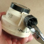
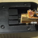
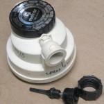
The female input connector often leaks, and the leak in this one made it completely unusable.  (According to reviews at Amazon this is a very common complaint, usually referred to as a serious design flaw.)  I had clearly had problems with this one, as there’s a blob of white marine epoxy over the screw hole (visible in the picture on the right).  But despite obviously having had it apart, I had no recollection at all how the connector was attached.

Just before going out to buy yet another one, I took one more look.  Putting an air gun nozzle between the connector and the body, I could see the copious spray of water was coming out between the body and the black connector part that went into the body.  Encouraged, I figured out how to remove the connector:  It’s just screwed in.  And while I’m sure Melnor has a special three-pronged wrench, pliers unscrew it nicely.  Aha – the screw keeps it from unscrewing.  The only reason I can imagine for making it that way is so it can be disassembled to fix the valve (the long black spring-loaded thing).  I’m all for making things repairable, but not if it introduces bad leaks.

And since I’m unlikely to put much energy into fixing the valve in this $15 device, I’ll bet epoxying the threads will be a fully acceptable leak fix.  (Hmm, although it might be nice to wipe crud off the small O-ring on the valve if that leaked a little.  Oh well – it’s all done now!)

I suppose for future reference, leaks like this could be addressed by unscrewing the screw, unscrewing the connector, putting a turn of teflon tape on, screwing it back in so the holes in the male threads and in the body line up and replacing the screw.  Leaks around the screw itself might require something like a gasket under the screw head or some kind of thread sealer.  Or use lots of teflon tape, epoxy over the screw hole and screw it back in.  Lots of tape because otherwise it’s possible to screw it in so far the female hose ring isn’t free to turn any more.  Or I suppose you could file away part of the fat outside ring on the body.

Posted in Home Repair | 10 Comments

Prius nav DVD replacement

The GPS in the Prius pretty much stopped working recently with an error message about not being able to read the DVD.  I replaced the DVD with another I found in my collection and it seems to work again.  Since I couldn’t find any notes about the history of the DVD hack, I thought I’d put down what I remembered before I forgot any more.

The nav system in my 2004 Prius came with a map ver 3.3 DVD (in the reader under the driver’s seat).  That worked fine, but after a few years I wanted newer maps.  Unfortunately, the only way to update the maps is to buy a $250 DVD from Toyota.  Boo.

The very annoying “safety feature” that you can’t do things like enter a destination address in the GPS while the car is moving became obvious very shortly after I got the car.  While such activities could certainly be distracting to the driver, there is zero safety issue with the navigator sitting in the passenger’s seat entering destinations, etc.  The car clearly knows when somebody’s in that seat (it has a separate seat belt warning), but that’s not enough to unlock the GPS.  Boo again.

A little googling found two solutions.  One was to install a switch to open the path from I think the wheel sensors that let the GPS know the car is moving.  I seem to recall something about a purple wire and rebuilding a connector in that hack.  I did that, resulting in a little switch in a film can living in the upper glove box.

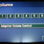
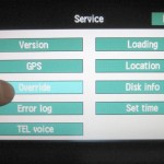
While that mostly worked, I came across a more elegant and effective trick.  By alternately pressing two invisible buttons (top, bottom, top, bottom), you get an undocumented screen on which a long touch will override the GPS motion-lockout.  It only works until you start the car again, but the only down side is that the navigator grumbles a little before entering the destination.  Fine.  Until the new map DVD.

The DVD contains not only maps, but (some of?) the software that runs the nav system.  Since Toyota  knew the override backdoor was known to the Prius hacking community, they took it out of later DVD versions – including the v 6.1 I’d just bought.  So – do I want the new maps I’d just paid dearly for or do I want the override capability?

Bless the Prius hacking community’s heart, you can have both.  By reauthoring a new DVD with most of the stuff from the new factory DVD, but I think one file (LOADING.KWI) from the old DVD, you keep the old software but get the new maps.  Of course any other improvements the new software contains won’t be there, but that was a tradeoff I was willing to make.  I got some Dual Layer +R DVDs, found some authoring freeware, and soon I had a new DVD.  Actually apparently more than one.

There’s something about two versions of the DVD – one with a full software image and the other with just software and map updates.  I’ve heard the full DVD is around $1000 as opposed to the $250 for a map upgrade disc.  When the nav system loses power (unplugged, 12V battery replaced, etc) it must read a software image from the DVD.  I don’t think the new DVDs I burned will load up from cold – must have a full factory DVD for that.  But they will run once the software is somehow loaded (like from the original disc I got with the car).  There are notes on some of the DVDs I found indicating they probably wouldn’t load, and I vaguely remember something about swapping DVDs after I made the new ones and maybe after the 12V battery was replaced.

When faced with a flaky disc now, the first step was to pull the DVD out and inspect/clean it.  No improvement.  Then I took the extreme step of putting the nozzle of a compressed air gun into the drive slot and blasting a little, hoping to dislodge the dust that might have been on lenses (and not doing any other damage).  Still no change.

I planned to put the 6.1 factory disc in to see if it was the disc or the reader.  But when I found the stash of discs there were three interesting DVDs with my handwriting on them.  One is marked “6.1 hybrid” (of old software, new maps), with annotation “worked fine for several years – bad sector at xxxx”.  The bad one in the car was marked “Prius hybrid nav 6.1 – 2nd copy 8/3/10”.  I infer that the flaky behavior occurred before, and I had a second copy of the same DVD image that worked after the first disc failed.

The third disc was marked as ver 7.2, also with the caveat that it probably wouldn’t load.  As I recall, there’s a text file with the version number, and I was probably playing around with that.  I put that one in today (5/22/12) and in a short test it seems to work OK.  It does come up as ver 7.2.  (That’s of course meaningless, since there is no ver 7.2 – or wasn’t when I made that disc.  I just made that number up to see what would happen.)  I no longer have a spare working disc, but I do still have the .iso I made them from, so if this one fails I should be able to make yet another.

I’m pretty surprised that two separate DVDs worked for a while and then developed a read error.  I very vaguely recall (at least?) one of the discs I burned when first authoring the hybrid DVD just didn’t work.  I also vaguely recall reading that people had different success rates with different brands of disc.  The one that apparently failed first was a Memorex; the one I just took out after failing was a cheap WinData.  Didn’t notice  the manufacturer of “7.2” disc in the car now.

I also vaguely recall that someone else wanted a copy of the hybrid disc, but I don’t remember who it was.

Update 5/25/12:  The GPS has worked flawlessly in the few days since I put in the “7.2” disc.  No more read errors.  Yay!

Update 12/28/13: The GPS started saying “can’t read DVD” again a month or more ago.  (Could have started much longer ago – I rarely use the car’s GPS any more now that I have the TomTom Go Live 1535.  But the TomTom was being flaky one day and I tried to use the built in one as a backup – and that wouldn’t work, either!)  That disk was a Memorex +R DL 2.4X, for the record.  Finally got around to making another new DVD.  Burned the file “6-1HybridWorking.iso” to a Windata DVD R+DL disc.  We’ll see if it works…

Update later that day: Had a little trouble ejecting the old DVD.  Looks like the car has to be booted up to do that.  Then moving the slider on the left over to the left ejected the disk automatically.  I put the new one in, moved the slider back, and it found the streets around the house.  Haven’t gone for a drive yet, but it seems at least somewhat readable.

Posted in Miscellaneous | 1 Comment

Oops – bad mulch

I just learned a little lesson about mulching.

I’d finally gotten around to seeding the ugly 6′ circle of dirt and wood chips where the stump was ground out after a tree was removed from the front yard last fall.  I’d raked the worst of the wood chips out, rucked up what was left, seeded, then weed-weaseled it again to kind of dig the seed in a little.  And of course watered it.

Thanks to exceptional weather, the rest of the grass was growing so fast I had to rake the clippings for the second week in a row.  My mulching mower usually does a fine job, and I almost never have to rake.  So I had a bunch of clippings I’d raked up in the front yard.  And I had this big circle of dirt with not-yet-germinated grass seed.  I needed to get rid of the clippings, and I figured the seeded area could use some extra protection from drying out if I forgot to water.  Aha!

I tried to sprinkle the clippings in a thin and uniform layer, but I had a lot of clippings and not a lot of patience, so I ended up with clumps of clippings in many places.

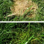
A week or so later, when I started to see baby grass coming up, I noticed it really wasn’t coming up thru the clumps of clipping mulch.  Curious, I picked up a clump.  A bunch of yellowed, frustrated baby grasses!  Oops.  I carefully and gently raked up most of the clipping mulch, and lots of baby grasses saw their first sunshine.  Maybe misled by how aggressively all the dumb baby maple trees sprout, I’d figured the clippings would present little impediment to the grass seedlings – but not so.  Here’s a  picture of an admittedly gross clump of clippings and what was underneath in a nearby bare spot I’d seeded at the same time.  Fortunately, I think I noticed in time to keep from killing much of my new grass.

The bottom line seems to be that using grass clippings for mulch for grass seeding isn’t a great idea – at least if you’re going to be at all clumpy about it.

Posted in Home Repair, Miscellaneous | Leave a comment

Tiny85 fuse resetter

The AT Tiny85 is a great, cheap ($1.29 qty 1 at  Digikey!) little processor.  At 8 pins, little is the operative word.  Assuming you don’t need an external crystal (a good assumption for 99% of the hobbyist use cases of this chip), you still get at least 5 I/O pins.  That’s 2 for power/ground, 1 for Reset, and the rest for I/O.  And if you really don’t need a Reset pin, you can burn the RSTDISBL fuse and get a 6th pin for I/O.

In making a little demo blinkie board for an upcoming Tiny85 class, I need all the I/O I can get, and that means using the Reset pin for I/O.  The downside of doing that is that the Reset pin is part of the normal In Circuit Serial Programming interface, so after you burn the fuse, you can’t reprogram it with a normal programmer.  That’s a little scary.  The $1.29 price tag doesn’t mean a lot when it’s Friday night and you’re down to your last chip!

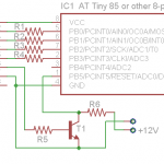
Atmel has provided a way out, but it requires a special “high voltage” serial programmer.  They’re available, but I’m cheap, and for the small number of times I’m likely to need it, I wanted something minimalist (and cheap).  I found just the thing on one of Wayne Holder’s Tinkering pages.  He even provided a sketch to read the device signature, read the fuses, write the default values, and reread the fuses.    It’s Arduino driven, one transistor and some resistors.  It does require a 12V supply, but for the rare times I’ll need it I can come up with 12V.  (Wayne has a later version which uses a charge pump to derive the 12V supply, adding only a couple of caps, resistors, and diodes and a few more Arduino pins to drive it.)

All resistors are 1K.  I used a 2N2222, but about any general purpose NPN transistor should work.

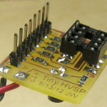
I laid out a little “mini shield” for it.  No need for a whole shield when all the pins I need are in the Arduino’s 8-pin header D8..Aref.  I don’t even need anything from the other side for +5V, since he just sets a pin HI and uses that.  (Nice arrangement, Wayne!)  I used SMT resistors, but wanted a socket for the Tiny85.  I realized part way through laying it out that the SMT stuff was being laid out on the foil side and the socket on the component side, and tried to make sure I took care of that little twist.  But failed.

The device didn’t work at all first try, and troubleshooting soon turned up the layout boo-boo.  The fix of putting the socket on the other side of the board is ugly, but it works.  And to my pleased surprise, the chip didn’t even get completely fried with power (and 12V!) on the wrong pins until I shut it down to figure out why it didn’t work.  It at least worked well enough to report its signature and fuse state after I fixed the programmer.  And if I blew some I/O pins or something – oh well.  It’s only $1.29 and I have some more. 🙂

Posted in Tiny 85 stuff | 3 Comments

Notes on DSL problem

My DSL internet connectivity via SBC/Yahoo/AT&T has been pretty good.  I’ve finally got some intelligence in the script that pings my ISP so it can power cycle the modem and router when it detects loss of connection, and I think that has helped a few times.  This note is to record some details of a failure that required a phone call to fix.

We lost connection tonight for an hour or so.  I could still connect to the modem (an old SpeedStream 5100) from the main PC, and ran the “Check Connection” diagnostics from its web interface.  That’s a pretty nice feature.  You’d think when I had a service tech on the phone and could say “The modem diagnostics show ADSL is OK, but ATM connectivity fails.” it would get me a long way toward not having to deal with “Did you reboot the computer?” questions.  Doesn’t help as much as you’d hope when you have a “tech” in Bangalore reading from a script.

I called the support number (1-877-722-3755, still named SBC in my contacts folder) and got an AT&T robot.  I think the fact that I was calling over the landline that hosted the DSL connection might have helped.  I interacted with the robot for a few minutes while it tried some diagnostics, and it finally handed me over to a human (or another robot that passed the Turing test – hard to tell).

I opened with what the modem diagnostics showed, including a little more detail from the “Details” button.  She seemed a little surprised, and that might have gotten me a pass on the first few “is it plugged in” kinds of questions.  She asked me to look at the modem lights, and while I was watching (power, Ethernet and DSL were solid green, Internet flashing green) it all went dark.  I asked if she had remotely reset the modem and she said she hadn’t.  Oops – the script on the Pogo was still live and probably still power cycling the modem (and router) every few minutes.  That was not going to help things, so I (climbed behind the water heater and) unplugged the router resetter PIC node from the network.  (I could have disconnected the wire from the node to the controlled power outlet, but it’s just a 2 pin header and I didn’t want to take the time to note which way it went so I could plug it back in correctly.)  I need to remember to do that before I call next time.

She ran some more remote diagnostics and (after several minutes) checked their outage database.  There was an outage of some sort in the Chicago area.  That didn’t stop her troubleshooting though, and after while she reported that there seemed to be a problem with my ATM provisioning.  Gee – that sounds real consistent with the fact that the modem said it could get DSL sync, but ATM OAM ping failed.  She continued and said she would fix the provisioning (!?).  Shortly thereafter (and maybe another manual power cycle) it all came up!  The modem showed all green pass marks, and I could connect to the Internet.

I thanked her and tried to get off the line, but her script apparently required her to offer me the “Connect Tech Plus” service to get better support for only $15/month.  I politely told her that was ridiculous, and she even had the good grace to laugh a little.  I thanked her and said good bye.

Within minutes it was doing the same thing again.  It did bounce, and occasionally came back up, but stayed mostly down for another hour? or more, pretty much with the same symptoms.  I’m typing this into a local text editor, since I can’t access WordPress.

So the takeaways are:

  • before I call, disable the stuff that can do automatic power cycles!
  • if it fails on ATM, maybe asking them to check the “ATM provisioning” could speed the repair process
  • don’t forget to re-enable the restart stuff
Posted in Home Automation, Home Repair | Leave a comment

Chasing recording preamp distortion

I’m dragging my feet on making up the final boards for the ‘production’ Sansa recording devices.  Much of it is that I don’t really trust the new ones.  I think I heard some distortion in some of the Sansa recordings some time, and I’m afraid I got too greedy and set the compression level too high.  It has spooked me so much that I don’t even use the latest prototype for live recordings – I still use my old faithful white box / Iriver 890.

That final size (smaller) device has the resistor that sets the compression level buried under the now-glued-in Sansa.  I’m torn whether to rip it apart and change the resistor or just use the new resistor in subsequent instances.

More troubling is the distortion I seem to recall.  It’s (obviously) either in the AGC/limiter electronics or in the recorder itself.  Since the 2167 implements a fairly hard limiter at the highest levels, it’s possible the problem came from that.

To test for distortion at high levels, I wanted to drive the electronics with a fairly high level signal, pick off the audio just before it goes into the Sansa and run that to a decent amp and speaker.  By listening closely as I adjusted the level control on the PCB (and using the LEDs as a level indication), I hoped to be able to hear any bad behavior at high levels.

I first tried to use the one remaining larger prototype, since the Sansa is socketed and it would be easy to change the compression resistor.  After various attempts, I’m afraid that one is dead.  There’s no audio out, and the averaging cap always has ~4V across it.  I can see audio coming into the 2167, so it’s good that far.  The top of the averaging cap is the DC level that runs the 3914 and LEDs.  In that old larger prototype, that signal goes through some CMOS switches intended to allow the LEDs to also show battery level.  (I ripped all that out in later smaller versions, and just use the battery gauge in the Sansa.)  But if any of that was bad, it could conceivably inject some DC onto that cap.  But when I cut the trace from the cap to the rest of the world (leaving the cap connected only to the 2167), the voltage remained unchanged.  Looks like the 2167 is dead.  Bummer.

Brief detour to make a tool

OK, I’ll use the little one.  And its high compression should help show any distortion at high levels.  First thing is to drive it with some high quality music I know well.  I’ve put a suitable collection of music on one of the old Irivers, and  that’s now my usual audio test source.  Hook it up and try it.  Everything sounds fine – but even with the Iriver’s volume cranked all the way up, I can’t even light the top couple of LEDs.  I’ve been aware of that shortcoming for some time, and I think it was what drove me to dig out the old 386 amp that inspired the “What a difference 30 years makes!” post.  But I still don’t have a dedicated amp to give me more signal.

I scrounged around and found a little dual-386 amp that drove the non-powered speakers on my desk at work for the last couple of years there.  But I needed that to run the output of the AGC/limiter to speakers to hear it.  If I had another one of those, that would be about ideal:  Gain of 20, and low enough output impedance to drive speakers should the need arise.  <digs around some more>  And in a great stroke of looking forward, I even made a spare board when I made the one for my desk!
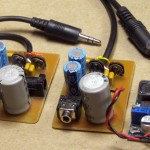
I drilled the board, found parts, and made up a new copy of the amp.  While the original had a coax barrel connector for power from a wall wart, I wanted this one to be portable.  To get good voltage swing, I needed around 12V, but didn’t want to mess with a 12V battery.  I found a DC-DC boost converter from another project that takes anything from 3.5V up and makes anything up to around 40V.  I’ll power it from 3 AAs.  Might make sense to leave regular alkalines in it so it will work when I need it, but pop some Ni-MH cells in if it will be used heavily for a while.
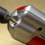
As is my custom, I put a pigtail on the new amp for the input lead (avoids the possibility of a flaky connector).  Unfortunately, the cable I grabbed to cut up had a big honking plug that wouldn’t fit in the unusually narrow headphone jack entry on the Iriver.  A little hacking relieved the plug and did the trick.  Yeah, it’s ugly – but it fits.  I have the tool – now I can do the testing I started out to do: crank the level up and see if I can hear distortion.

Looking for distortion

I had done something similar when I first set up the new electronics.  I played with it, watching the LEDs as I decreased the level down to the noise gate, and set the 3914’s RefLo voltage so if even the bottom LED was on, it was still above the noise gate.  I’d tried to set RefHi so as long as it was below the top LED, there was little or no distortion.

This round of testing only confirmed that I’d done what I set out to do originally:  If I cranked it up enough I could hear distortion – but I had to be above the top of the LED scale to do it.  Hmm – that leaves the specter of the Sansa recorder being not as good as the Iriver – and maybe not up to the task of the high quality recording I want.  That would be bad:  I’m pretty heavily invested in this approach – and using the Sansa recorders.  I just counted noses and I’ve collected 10 of them so far.

I think I did one round of A-B recording with my ‘good’ setup and a 2167/Sansa at the same dance.  I’ll try to find that and do some critical listening.

Hmm – found two sets.  One was white box/Iriver vs 2167/Sansa.  But that was before I had firmware with appropriate levels, so the Sansa recordings were down by 2 bits (factor of 4, or 6dB).  The other – from 3/5/12 – was 2 Sansas, one with no compression, other with 100K resistor -> high compression.
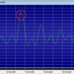
In listening to the latter, there were places with loud clear voice only, no music, where I can hear a little distortion.  Clipping?  Looking at the recordings in GoldWave, I could almost convince myself there was some of the peak folding that I think might be digital clipping.  The period of the glitch in the circle (at 5:54.658 in R120305-195354.mp3) is 0.00007 sec, or  a cycle of about 14.3KHz.  There can certainly be any frequency components at any time, but there’s nothing else nearly that high in the neighborhood.  The 2167 is all analog, so if it is a digital artifact, it’s the Sansa’s fault.  Hmm – there’s a soft level control in the Sansa that I think controls an analog stage just before the A/D.  While I set that so I never see recorded values at 100%, I wonder if backing it down a notch (which is 1.5dB) might reduce this distortion.  Or, since I think I have more than 1.5dB headroom, if increasing it would increase how much of this occasional distortion I see (hear).

Sandie was using an MA-150 amp, which I expect is all analog, but as one of the latest bits of Hilton gear, I suppose it might somehow be digital.  To rule out distortion from the Hilton, I found the same spot in the non-compressed recording.  The spoken phrase sounds some different, as it has a large dynamic range, and the compressed version is pretty much all at the same recorded level, while the dynamics are audible (and visible in GoldWave) in the uncompressed version.  But after tweaking the levels so they sound the same and doing repeated A-B playings of the two, the critical observation is:  the uncompressed version sounds fine – the obvious distortion in the compressed version is just not there.

Guilty party?

So the distortion comes from either the 2167 electronics or the recording action in the Sansa.  Which one?

The voltage controlled amp in the 2167 is known to introduce some audible distortion on peaks, due I believe to a design flaw.  I think my hack of reducing the signal between the initial buffer amp and the VCA should avoid this distortion (at a cost of signal level).  And I just did some careful listening audio testing (with the new dual 386 amp) picking audio up on the lead going into the Sansa, after the 2167.  And even cranking the signal level through the 2167 way higher than it deserves to go, I heard little distortion, and certainly not as harsh distortion as I hear in the compressed recording I’ve been working with.

So that really sort of points to the recording hardware/firmware in the Sansa.  I guess that defines the next test:  Going through a 2167 with high compression (like the one small version I have), record to the Sansa but change the record gain up and down a bit.  If I can recreate the distortion and it goes down/away at lower record levels, I’ll take it!  The current record level hits peaks ~90% (-1dB), so I could certainly afford to take it down some.  I’ll use the same block of Sandie’s voice I’ve been looking at above – from the uncompressed version, of course – for source material.

Hmm – not what I expected.  My standard recorder gain is 0dB.  I recorded at +1.5, 0, -1.5, -3dB.  I clipped one phrase from the source and from recordings at -3 and +1.5dB and normalized the volume.  Testing consisted of playing that 5 sec recording in a loop and trying to hear differences. The original sounds perfect; the other two are both distorted and as far as I can tell, indistinguishable.  (“Everybody” is the most distorted word.)  So a 4.5dB change in recording gain produced no audible difference.  Doesn’t sound like a clipping problem in the recorder to me – unless it’s early in the audio path.

Improvements to the new device

That leaves the 2167 electronics.  There are two possible problems.

First, I’m unhappy with the sound of the high compression.  I don’t know that it’s causing distortion, but I don’t like it.  Unfortunately, I have to tear the glued-in recorder out to get at the resistor that controls the compression.

A second possibility is an unjustified resistor value change I made in my hack to reduce distortion/increase headroom.  The initial buffer amp is connected to the VCA by an external (10uF) capacitor.  There’s an internal 1K resistor in series with the output of the first amp.  My hack was to connect an external 1K to ground on one side of that external cap, cutting the signal in half.  With that in place, the VCA produced much nicer sounding output.

In this version, I changed that external resistor from 1K to 1.5K, to give a little greater final output.  I did that unilaterally, with no testing to verify that it still works OK.  Of course that raises the signal level to the headroom-constrained VCA.  Fortunately, that resistor is easily accessible.  So one step in the next rounds of troubleshooting is to swap that out for a 1K or maybe even an 820Ω, having carefully made reproducible recordings before the swap.

Another step would be to cut the input level to the 2167.  That would do almost the same thing as decreasing the level with the lower hack resistor value, giving the VCA less excuse to distort, at the cost of moving closer to the scary noise gate.  But at least it’s an easy test 🙂

<testing…> I couldn’t hear any significant difference between two recordings including the distortable “everybody…”, one with the input level pot on the 2167 board set to about 40% of the other.  But I guess that makes sense:  While we had noticeably less signal going into the VCA, the AGC part would have cranked the gain control signal up to try to make up for it.  And if the distortion occurs in the output section of the VCA (which is what has to handle the largest signals), we’d have almost the same levels in the two cases.  And the actual recorded levels of 13.9 and 14.1dB support that.  Oops – bad test.  OK, OK, I’ll swap out the dumb 1.5K resistor.  Since that’s after the AGC detector but still before the VCA, we really should get a smaller signal out – and maybe a less distorted one.

I was going to use an 820Ω, but since I didn’t have an SMT one I used a 1K.  I couldn’t hear any significant difference between before/after recordings.  I was surprised at how similar the recorded levels were – 14.7 v 13.9dB.  But after I did the math – 1K/2K vs 1.5K/2.5K is 0.833 or 1.8dB.  Close to the 1.2 I saw.  So that change didn’t make much difference.

Hmm – what if the distortion is in the Sansa’s very input section?  If it were before the recording gain control, changing the gain would not change anything – just as I observed!

There’s a 22K resistor between the output of the 2167 and the Sansa input I could use to further reduce the signal, but again I can’t get to it.  Between that and the fact that I’ll never trust that device until I can get the compression down, I guess I’ll have to tear it apart.  Humpf.

Tore it apart.  The servo tape holding the PCB to the case held well, but released when I pried at it.  The hot melt came off more easily than the last time, since I used less 🙂  I unsoldered the 3 wires to the Sansa, but they were loose:  The hot melt holding the little PCB those wires are attached to inside had let go.  Disassembling the Sansa had an additional benefit:  The 4-way ring rocker switch was not seated correctly and didn’t work as smoothly as it originally did.  When I pulled it all apart I was able to seat it correctly, so the buttons should work nicely now.  Of course since I don’t use those buttons in normal operation, that doesn’t matter much.
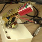
But I still don’t know what compression value to use.  So I pulled my dear old “gold standard” white recording preamp apart and wrote down all the component values.  The resistor that sets the compression ratio is 68K.  From the 2165-1 doc, that should give a ratio of 5:1.  Now I know what to shoot for!  In the 2167, 5:1 is 75K.  Like I have one of those lying around in 1206 size.  I re-laid out the board for 2 resistors in series for the next rev.  68K+6.8K is real close.  Now I need to replace one (100K) resistor with two on the existing board.
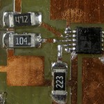
Done!  I got lucky with the available space.  A couple of cuts with an Xacto knife and I even had a chunk of isolated copper to make the junction.  This shouldn’t affect the distortion, but it should make it sound a little better by not so aggressively cranking up the gain on the quiet parts.

I swapped the 1K “hack” resistor (had been 1.5K) for 680Ω to give myself a little more headroom in the VCA to possibly better cope with low supply voltage at the end of battery life.  It will cut output level a little bit, too.  But I’ll swap out the 22K in series with the 2167 output for a 33K to reduce the input to the Sansa more substantially.  If I really was putting more into the Sansa input than it could handle, that should help.

After I put it back together, one of the first things I did was reset the Sansa’s clock so the timestamped file names would be correct.  To do that I needed – the buttons on 4-way ring rocker switch.  So I got a little quicker payback on that one than I expected.

To test it out, I made recordings with both the new box and my standard white box.  The white box sounded fine, but to my amazement, the new box sounded as bad as ever, even showing no apparent change in the compression!  WTH?  I took both to a dance and made simultaneous recordings.  In those live recordings, the ones made with the new box were virtually indistinguishable from the ones with the white box.  That’s just what I hoped for, but flies in the face of the test made earlier the same day.  What’s going on?

I redid the A-B bench test, but this time (like the live recordings, and matching my expectations) the recordings were almost indistinguishable.  All I can imagine is that I made some clerical error – picked up a wrong file – that led to incorrect results from the first test.  It’s pretty disconcerting when you design and perform a very simple test looking for very specific information, get the results (even though they weren’t the desired or expected outcome), and later  upon redoing the test conclude that the first test was invalid, but for reasons you can’t explain.  Boo.

But the good news is that now the new box works.  I double-recorded another dance, and again, the results are almost indistinguishable.  Treble on the new box might be slightly less bright than the white box/Iriver, but it’s good enough that I’m now willing to use the new box for recordings I care about, and now I can (finally!) proceed to commit the design to a production run!  I never did find the source of the distortion I was after, but as long as it sounds good now, I’ll take it.

Update 5/20/12:  I’ve used the newly tweaked device at three dances recently.  All the recordings came out great.  It even passed the test of recording from a Tape Record output on a Hilton 75A – one of the lowest level signals it’s supposed to work with.  Indication was one or two LEDs lower than ideal, but the recording was  still just fine.  I’m finally really willing to use these guys in earnest and put my name on them for others.  I still have to lay out a 5×5 cm board, re-find the board house that will do those for a buck, etc, etc.  But at least the design is now sound.
Posted in Recording preamp/limiter | Leave a comment

RG LED breakout quickie

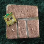
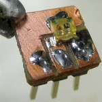
I wanted to use an SMT red-green LED for a demo board for the Tiny85 class, but for initial development I needed something breadboard friendly.  Quicker than laying out and etching a real PCB for something this simple, I just cut some insulating paths in a scrap of copper clad.

Holding some 0.1″ header against the board, I marked where to drill holes for the three pins with a scribe.  I also marked where the solder pads of the LED would go (a little crookedly, it looks like), and used the marks to decide where to cut.  A good technique for cutting away copper was two passes with an Xacto knife at angles to make a sort of V shaped groove.

After drilling I soldered the pins normally, but used my new friend solder paste for the SMT pads.  I had to be careful locating the LED to make sure the two anode pads didn’t touch the wrong places, but after I did the solder paste helped a lot in holding it in place.  You can see a little ding from the vice grips I used to hold it while drilling.  Works fine.  Another quickie success!

Posted in Tiny 85 stuff | Leave a comment

Trickle current limiter for B&D charger

I’ve worried for years that at least some of the NiCd chargers’ trickle charge regimen was cooking my batteries into oblivion.  They say you can charge sub-C NiCds at 100mA forever without problem, but for stuff that’s charging for months at a time (like lawn care tools over the winter) I’d like considerably less.

After I rebuilt one of the 18V sub-C batteries for my B&D “Cordless Broom” blower, I wanted to treat it well.  Leaving it on the factory charger resulted in it being quite warm after while, and a check (with a 0.1Ω resistor in series) showed it was still pumping a little over 200mA through the battery.  I need a current limiter!

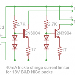
I found a fairly simple limiter circuit that seemed appropriate.  When the current thru the emitter resistor causes a voltage drop around 0.7V, the transistor starts to shut off.  Using that design, I started out to make something to use my one charger to trickle charge my two batteries more appropriately.

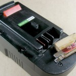
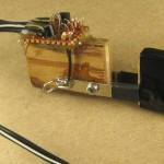
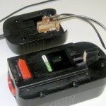
The first order of business was making contacts to plug into the charger and battery.  To connect to the charger, I simulated the battery contacts with a couple of pieces cut from an old PC expansion slot cover epoxied to a scrap of wood.  Using an oversized piece of wood ensured that it could only be plugged in one way.  (The geometry of the charger is such that the red + marking is correct despite the apparent mismatch with the red + blade of the battery.)

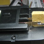
To connect to the battery, I fashioned some springy clips out of brass strip and epoxied those to another scrap of wood.  Again I located the contacts on the wood so it could only plug into the battery one way.  I added some heat shrink and tape to make it a little more proper.

I built the 2 channel current limiter on a bit of perfboard and glued it to the fake connector that plugs into the charger.  (I used 2N2222s.)  I also put a 0.1Ω resistor in series with the whole thing so I could measure current if I needed to.

Since the male input connector and the female output connectors matched, I thought I’d see if I could make it self-powered by plugging the output into the input.  (I could still use the second channel to trickle charge one battery.)  Unfortunately, the current limiter just got real hot and burned out the transistor on the side whose output I was using, so it didn’t work.  I guess perpetual motion really doesn’t work 🙂

It’s still a little bit of a hassle to use.  For a normal recharge, I slide the charger on the battery just like the manufacturer designed.  The charger is rated at 210mA, so after maybe 6 or 8 hours bulk charging is complete, so I take the charger off and plug the trickle current limiter into the charger and the battery.  But now I’m comfortable leaving it that way all winter!

I did run the blower with the rebuilt battery after it had been on the trickle charger for a couple of days.  It worked great.  And when I get around to rebuilding the second battery, I’ll also make another battery-end adapter for it.  The charger should be able to handle two 40mA trickles at the same time.

Maybe the next limiter will be for that dustbuster that lives under the sink, is always warm when I pick it up, and whose battery never seems to last very long.

Posted in Battery Charging | Leave a comment

Possible Glass Curtain Gallery presentation

I got kind of excited by the prospect of giving a talk at Glass Curtain Gallery about how artists and hackers could work together, and demo some of the sensors and outputs we could show them how to control with a micro.  I sent an email to the address in the request for submissions Jon Cates from dorkbots forwarded, and receiving no reply, looked up and left voice mail for Mark at the Gallery.

I don’t know if he’s just out of town or something, but there’s a growing possibility that what I’m offering is not of interest to them.  (Though I can’t imagine how that could be!)  So I’m throttling back on thinking about just what and how I’d present, but wanted to capture what had come up between my own thoughts and suggestions from other W88 folks before I stopped.

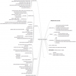
I used the open source “mind map” tool Freemind to capture and organize thoughts so far.   The tool isn’t perfect (and/or I’m not a pro with it!), but it’s still pretty useful.  I’d say this map’s a work in progress, but I’m trying hard to not spend any more energy on it unless I hear back from Mark.

If I do hear back, I’ll use this post to collect and polish ideas into a presentation script.

Update 4/20/12:  People keep offering cool new stuff for this, and I just add it to the mind map.  I rejiggered the links to the image above so I can easily export a new image and push it to where the link above points without going thru the hassle of updating this post, deleting the old image, and adding a new one.

Update 5/2/12:  I got a nice note back from Mark saying he was quite interested in talking to me about the presentation, although they were quite busy until May 15 with arrangements for an earlier exhibition.  I’m glad I captured my thoughts about this.  Guess I can think about it again 🙂

Update 5/8/12:  I just spoke with Mark.  He thinks the presentation I’ve described would be a good fit for their program, and is going to discuss it with his co-curator.

There’s an exhibition that will be on display in the September-October time frame, and a part of it will be the “Research Lab” in a sort of back room.  It will contain projects with explanations, demos, videos, manuals, and other resources for the students to browse.  My presentation would be part of that.  He pictures having it fairly early in the run of the exhibition.  Doing the presentation more than once is a possibility.

Anyway, (subject to agreement from Mark’s cohort) it looks like it’s on!

Posted in Artist / hacker synergy, Workshop 88 Stuff | 2 Comments

Little electret mic preamp

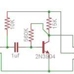
Russ said he had trouble using a bare electret mic as an input device in his Arduino 201 sensors class.  I hope to help by making up a couple of simple mic preamp boards.  There was an initial prototype, and a short ‘production’ run with a better layout, allowing a smaller board and putting the header pins closer to the edge so they don’t obscure as much of the breadboard.  I stuck a couple of the mics pulled out of the Sansa recorders on to try them out.  I also played with code ’til I got a decent one-LED PWM “applause meter”.

It’s a very simple one transistor amplifier, and the output still rides on a DC offset, just like with a standalone electret mic.  That was mostly so the students would have to deal with the DC offset.  Overall gain is about 100.  With one sample board, the analogRead() DC offset is about 320 (of 1024) and a loud noise gives a peak around 650 higher than that, so it’s a pretty good match for the Arduino’s A/D range.

I tried a couple of approaches in the code to automatically remove the DC offset and “rectify” the signal.  Final result was running batches of 600 reads (about 70 ms) and keeping both the max reading and the average over that time.  With that many samples  effectively at random times within the audio waveform, statistically we’re pretty likely to hit close to at least one near-peak reading each run – and it seems to work pretty well in practice.  Students can start with a simple version of the code ( loop() is only 9 lines).  There’s also a fast attack/slow release feature in an independent, additional block of code.  The code is in the W88 shared dropbox under Arduino201ScratchSpace.

While the target use case is on a breadboard, since I’m lazy and wanted to try it out on a bare Arduino, I put the 3 header pins in A0,A1, A2.  I used one as the obvious analog input, and the others as digital outputs, one constantly putting out HIGH, the other LOW to provide approximately +5 and ground.  Worked fine.  It responds to normal conversation maybe 2 feet away from the mic with a visible brightening of the LED.  A handclap shows a bright attack/release.  I hope Russ finds the boards useful.

Posted in Miscellaneous, Workshop 88 Stuff | 5 Comments