Random colors with RGB LED

Partly trying to have something fun to demo and get juices flowing for the kids in the new STEM Explorer Post 314 we’re trying to start up, I thought I’d try to make a smoothly randomly color changing RGB LED while they were experiencing the joys of their first ‘hello world’ blinking LEDs.  We’re bringing them up on Parallax BOE Bots (courtesy of the electronics lab at TCD) which run on Basic Stamp 2s, so it seemed appropriate to drive my LED with the same controller.  PWM in Pbasic 2.5 is a little cruder than on Arduino, but should be sufficient.

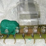
There’s an RGB LED kicking around in my Arduino box I’d made up a while ago with resistors and breadboard-friendly leads waiting for a chance to play, so that was the obvious target hardware.  I’d drilled out a roundish translucent white button and hot melted the 5mm LED in it for a nice diffuser.  I think I’d chosen the resistors trying for sort of equal brightness for each of the LEDs, though apparently I didn’t do a great job:  blue is noticeably dimmer than the others.  I had to read the cryptic connection note I’d attached a few times before it made sense.

Another requirement was that it should stay about the same overall brightness all the time.   OK – how to compute the 3 brightness values?  How about 3 random numbers (let’s normalize to 0-1 for each)?  No, with some of each color every time, I’d never hit pure R, G, or B, and my vision certainly included those colors.  How about dividing each by 3?  No, still no pure colors.  And overall brightness changes, too.  Hmm – harder than I’d expected.  I didn’t get it to do anything but blink on the BS2’s that first night.

OK, how about a ‘color wheel’ approach?  R,G, B at 0º, 120º, 240º and pick a random ‘hue’ number 0-359?  The pure colors are certainly possible that way.  I could apportion brightness between the two colors bounding the random value chosen.  But that doesn’t nearly cover all the possibilities:  if I chose say 60º, half way between R and G, there would be no B at all.  So what are all those excluded colors?  If I have half R half G and start to add some B (adjusting R, G values down to keep constant brightness), it gets closer to white.  So the simple color wheel gives me only fully saturated colors.  Those are certainly pretty, and maybe a good simple starting point.  If I miss the more pastel shades I could add another random variable that controls how much of the missing primary is included.

It slowly dawned on me that while my (hardware-based) blinders kept me thinking RGB, what I’ve described is essentially the HSL color space.  It’s always amusing to discover that you’ve reinvented some standard thing 🙂 .

That approach should work pretty well.  I get nice saturated colors (all of them, not just pure R, G, B), and I can skew the distribution of saturation values to favor high saturation, while still hitting white occasionally.  And if I miss having brightness variations, I could scale each R,G,B value with an additional single random brightness multiplier.  If implemented, the distribution of brightness values would certainly be skewed toward high brightness.

A quick try on an Arduino (since I don’t have a BS2) using analogWrite() PWM scaled 0-255 was a bad fail.  Took a while before the face-palm moment when I remembered it was a common anode LED, so bright was 0, not 255.  It got much better when I added a couple of “255 -“s in appropriate places.  But that was when I noticed how much dimmer B was than the other colors.  Fine – I’ll #define a max brightness for each, with B 255 and the others suitably derated.  Oops – yeah, it’s maximum brightness, but minimum PWM value.  I’m not an OO kind of guy, but it started to look like a really good idea to encapsulate all this brightness-value-inversion-with-per-color-scaling crap in a custom  set-brightness function for each color, with a nice normalized 0-1 input value.  That abstraction would allow for swapping in a common-cathode LED, as well as allowing me to concentrate on the aesthetic side of how to skew the saturation and brightness values to make it look ‘just right’.  Whatever that means.

More when I actually have some working code instead of just hot air.

Posted in RGB LED stuff | Leave a comment

Major progress on LED display

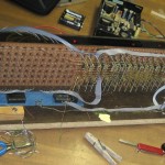
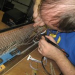
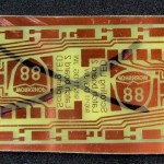
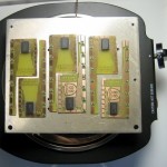
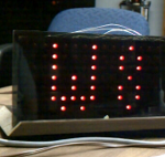
After another evening at W88, there’s some good progress on the display.  First, there are four boards running in the display that I didn’t have to make!  I did etch them, but Bill and Karl ground them down to size and cut them apart.  Then Bob Magyar stopped by and was pressed into service applying solder paste, placing components for reflow and then cleaning up solder bridges, etc on the boards.  I did the reflow on the hot plate.

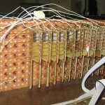
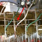
While the guys were prepping the boards, I ripped out the old rats nest of wire wrap column select lines now used as latch clocks and replaced it with a couple of much neater ribbon cable assemblies I’d made up at home.  Each ribbon carries 16 clocks (one 74154’s worth), so the two I put in will take care of the first 32 columns of latches.  I also ripped out the wire wrap tying the rows together for the rest of the first 32 rows.  Having the new latch clock loom in place makes connecting the clock for each new board much nicer.

I put in three boards that were completely ready to go from the last session, plus four of the boards Bill and Karl cut and Bob populated and tinned for a total of 20 running columns.  I thought the board tester was at the space, but it was at home, so the new boards went in without pre-test.  I did still fire the display up after each new board just in case, but all worked fine.  I brought the other six boards the guys cut back home.  Maybe I’ll finish those up at home  and etch some more doubles for others to prep for the next session.

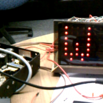
It’s looking more and more like a display.  I touched up the crude hard coded scrolling code a little and put in a pattern for full text of “Workshop 88”, but couldn’t find it (and so thought incorrectly I’d forgotten to transfer it to the netbook I carry to the space).  That was probably because the dumb IDE doesn’t reread the sketchbook folder when you try to open a sketch – only when it starts.  I had the IDE open when I looked.  Boo.  Anyway, it’s looking good.

There’s nothing magic about scrolling right to left.  Given a buffer of pixel data, vertical scrolling should be doable.  Maybe the final code will include as part of the message coming in the serial port a mode byte specifying which of multiple display modes the message should be presented in.

Posted in Scrolling LED, Workshop 88 Stuff | 1 Comment

6 more latch boards for scrolling LED display

We have 6 more (working!) boards in the display.  The goals were to see whether it looked good enough to continue the project and to get scrolling code working a little better.  Made only partial progress on both.

I tested each board before installing any, and then tested the whole display after installing each one to avoid hassles of trying to fix/remove a board in the middle.  Unfortunately, my netbook battery died after the 10th board, so I couldn’t touch up the code to address more columns, so the last 2 tests were using the column clock from the wrong column just to see if they worked.  I could never see all 12 columns actually working to try to make a decision about pulling the plug.

Andrew and I argued through the code a lot, but while we improved it, we could never make it scroll correctly for arbitrary numbers of columns of pixel data and physical columns of LEDs.  It was OK for some numerically related counts.  That’s still a mystery.

Andrew installed the first board.  I installed the rest after he left, since I didn’t have to go to work the next day.

There was an oops making the last pair of boards.  I had a whole cleanly etched board before I realized I’d put the artwork on upside down.  Nobody to blame but myself.  Hate when that happens.  I’ll keep the board to remind myself to not screw up.  Fortunately I had enough time to redo the pair.

I reflowed all 6 boards at once – the most I’d done at one time.  Since they all become ready at just about the same time and it takes a little time to slide each one off the plate, that’s too many to manage at once. Temperature of the plate continues going up after the solder melts, so it’s critical to get them off as soon as they’ve reflowed.

I bumped the chip on one while trying to hussle them all off.  I had the presence of mind to then bump it far enough off that it was sitting on bare board so it would be easier to remove to fix.

Having gotten all 6 off the plate (though the last ones were discolored from having stayed on too long) I decided as long as the board and the plate were still very hot I’d try to rework the bumped chip on the hotplate.  I used a large tweezers to pick it up and relocate it, and it seems to have worked out OK.  That was an interesting exercise.  Much better is to not mess up in the first place, but rework on the plate seems to be a workable approach.

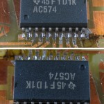
As I examined the boards later to clean up solder bridges etc, I found that another board had had its chip disturbed.  One side was slightly less than 1/2 pin off, and might have worked.  The other side was more than 1/2 pin off and so actually connected to the wrong places.  Using solder wick to heat all the pins on one side at a time and a knife blade under the chip I managed to lift one side.  The second side was easier.  I resoldered it by hand without incident.  Despite concerns of overheating both in this resoldering effort and from leaving boards on the plate too long, all 6 boards/chips survived and work OK.

Update 3/23/12:  After lots of analysis, testing and code review, Dan, Karl and I got the display scrolling without artifacts.  Main problem was which edge the latches latched on.  The logic was flawed, and the latching edge (lo->hi) occurred one column step off.  Anyway, the code works now, though only if the number of columns of data is > number of physical columns of LEDs.

It’s not perfect, and one LED – about 3rd from bottom, about 10th col from left – occasionally fails to latch right.  But it’s pretty good.  There’s lots of work ahead, but I guess I’ll continue.  I hope to get some help with the grunt assembly.  As Karl very appropriately suggested, I should ask for the help so people know I’d like it.

The latch board tester has been improved (I hope!) with some Sugru as a place to push on to make contact.

Posted in Scrolling LED | 1 Comment

Battery tab welder has foot pedal and charger cutoff

Faced with a potentially large number of welds for rebuilding a DeWalt battery, I finally integrated two improvements that have been waiting in the wings:  a MOSFET charger disconnect and a foot pedal to disconnect the charger and fire the SCR (in that order).

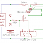
Here’s the  new schematic.  The MOSFET cuts off power from the charger momentarily during discharge so it doesn’t keep the SCR turned on.  Since the gate needs a few volts to keep it turned on, powering it from the top of the cap doesn’t work for the end of the discharge cycle – thus the battery.  I was originally going to put 3 AAs in, but realized a 9V battery past the end of its useful life would be perfect.  And I have a lot of those lying around.

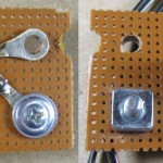
I built up the MOSFET on a bit of perfboard and found a nice mount for it on a thermal cutoff or something in the charger housing that passed the low side lead.  A four position terminal strip provides connections to the foot pedal switches.

Since I was in a hurry <sigh> I wired it all up, but didn’t do final mounting.  The wires for the foot pedal just come out of vents in the case, and it’s all just kind of hanging in the breeze.  But it was sufficient for the job at hand.  And it all worked together perfectly.

Since the power supply can generate DC voltage greater than the cap’s absolute max, I had to cheat to protect the cap.  After each weld, I’d remove the electrodes and then quickly hit the foot switch again, cutting power to the cap while I lined up the next tab.  I’d position one electrode, but since the foot switch being down left the electrodes potentially hot (oops) I’d take my foot off the switch before I positioned the other electrode.  Then I’d watch the voltage climb to the desired ~15.5V and hit the foot switch again to make the weld.  The undesirable noise and sparks kept me from blowing that sequence of events more than about once.

So the next, and final (well, maybe except for a handle) improvement (OK, and mounting those last parts more permanently) is a voltage/power control.  The “wire or” MOSFET control design should allow for this nicely:  Any other closure to ground will also disconnect power from the cap.  All I should need is a comparator on the cap voltage with its other side on a pot, all turning on a relay or transistor when the voltage meets the setting.  A voltmeter would be nice, too.  And maybe when I make that I’ll mount all the parts neatly as well.

Posted in Battery Tab Welder | 1 Comment

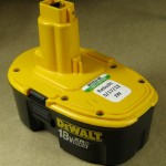
DeWalt battery rebuild

What better birthday gift for my friend Ed than a handmade rebuilt 18V DeWalt battery made from recycled sub-C cells?  OK, especially when he provided 2 of the old packs I scavenged from.

In addition to Ed’s donations, Mike D from where I used to work gave me some old DeWalt batteries suitable for recycling.  I’ve had them for maybe a year, so it was time to get moving.

All 4 packs read much less than 1V as I started the project yesterday (last Saturday).  I started charging up the packs for cell testing.  The DeWalt chargers seem to reset when you remove the battery, and I put each one into a charger a couple of times to get as much into them as I could.

One pack came up “bad” (fast flashes of the charger’s one LED) every time I plugged it in, so I tried a more brute force approach.  I put a big power supply across it with 22 ohms in series.  I let it cook with about 0.25A for a couple of hours.  Terminal voltage was about 3V – not good.  I ran a couple amps thru it for a few minutes (with a blast of maybe 5A for a few tens of seconds).  Terminal voltage came up to 8V – maybe there’s a little hope!  I put it back on to charge at 200mA (still with the 22 ohms) for maybe 15 or 20 hours.  As I checked in on it a few times, the current kept creeping up, so I’d turn the voltage down to get back to 200mA.  The battery terminal voltage was falling (which makes sense with the current increase), so I didn’t hold out much hope.  It was time to start doing cell testing, and that was the battery in the middle of the bench, so I tore that one apart.
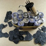
Opening the case was no problem – six T10 screws came out easily, and the case split apart nicely.  Pushing on the terminals in the tower pressed the top cell out.  There was a small strip of black foam tape involved.  The only thing holding the cells in formation is some thin fiberboard contact cemented over both ends of the cells.  A thermistor was visible and taped in a hole in the fiberboard to make good contact with a central cell.  I added a rubber band to keep the cells from flopping around.

It had been off the charger for not more than an hour by the time I opened the case and got the cell ends exposed.  Terminal voltage was down (from 7V) to about 2.2V.  Not promising at all.  I found the two cells that were not completely flat and peeled the tabs off the other cells, leaving both tabs on both cells.  The tab material is about .0075x.433″, with the ends split and 2 spot welds on each split.  That material is heavier than what I have, so I’ll have to salvage tab material as well as cells.  I guess the good news is that this very dead battery should donate a lot of tabs.

I hooked the two not dead cells in series and started a discharge test on them.  Ugh.  Wasted a couple of hours trying to get a decent test of those two very marginal cells.  The discharger seemed flaky – either 2.6ish or 0V.  Wiggled stuff, tried a different Arduino, reseated the analog switch chip with ProGold snake oil contact enhancer, doubled lines of code like enable, analogRead().  Finally tried it with a good 12V battery – results were fine.  Gave up on those 2 cells.  So that first pack provided zero cells.  Still a source of parts and tabs, though.
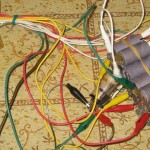
Second pack read 17V fresh off the charger, so we expect some bad cells.  Construction was a little different – top was lightly glued and edges taped.  Hooked it up to my good 16 channel discharge tester, but had some problems.  Updated discharger code to fix a few bugs and allow deep discharge/reverse charging for cases like this where I don’t care about the bad cells.  Got a good discharge run.  Looks like we have one, possibly 3 useful cells.  Next!

Not so good.  I thought I did everything right, but it didn’t work, and the DG406 analog switch chip got VERY hot.  Now it doesn’t work, so I no longer have a discharge tester for this rebuild.  There’s no way I can get a new chip before Ed’s birthday on the 17th.
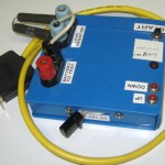
Resurrected my old single channel discharge tester.  (Yeah, it’s built in a 5.25″ floppy box.)  Not great, but I should be able to see cells fall off (though I won’t know which ones).  And it will automatically disconnect the load when the voltage drops to a value you choose.  If I run it down to say 8V or something, one measurement of each cell will show me the bad ones, and I don’t care whether a particular cell failed early or late – it failed.

But no joy.  All it would report was zero V from the battery.  I tried Pro Gold snake oil on the range select switch – no better.  I found some project notes and the board layout and started troubleshooting.  I could see which processor pin was the analog in, and when I looked at that pin I could see the voltage from the battery – though it was still reporting zero V.  OK, that one’s dead too.  This is not going well.

As long as I had done some moderate troubleshooting/reverse engineering, I added what I’d found to the project doc, took a couple of pictures, and included the board layout image in the doc.  That way if I ever come back to it, I’ll have a clue what to do.  It’s even possible that it might get reincarnated:  All the binding posts, relays, range switching/scaling are  there and still good.  I might put a header in the PIC socket to bring out the interesting lines and put a 4313 or something in.  Or maybe I could even find the PIC code again and burn a new PIC (if I have that one).  Anyway, that attempt is closed for this project.

Digging deeper, I found an old Craftsman multimeter with an RS232 interface, hoping I could at least use that to log the terminal voltage while discharging with me watching to decide when to kill the test.  The meter worked fine, but I couldn’t find any installed software.  I did have the install zip, but that install (from 199x?) failed on my Win7 machine.  I tried a terminal emulator to talk directly to the meter, but no luck.  To my delight, I found the protocol doc online.  600 baud 7n2, send a ‘D’ to get a data point.  Still no luck.  Changed the (1999) battery – no luck.  Found a 9 pin Rich serial tester – no data (or mark!) from the meter.  Ran XCTU and  in desperation tried playing with handshake lines.  With DTR on and RTS off it worked!  Ran the incompletely installed software it came with and that started working as well.  I really don’t know what fixed it.  Anyway, it’s now logging terminal voltage every 30 sec.  I have to sit here to watch over it, but at least I’m back getting some data on which cells I might harvest.
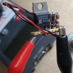
…Except I don’t trust the 9V that’s running the meter to last for hours and hours.  So I made up a quickie 9V replacement with a 7805 (‘cuz I have a lot) and a 1K/390 divider for 8.4V.  A 12V lead acid battery should run it plenty long enough.  Took longer than I wanted, but it’s there and powering the meter.  I’ll keep it in a little bag taped to the meter when this is done.
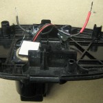
As I was frequently charging packs that were no longer in their nice plastic houses, I took advantage of the growing pile of spare parts and made up something that would plug into the charger and provide nice clip-lead-friendly wires as output.
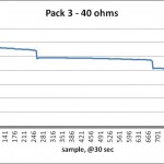
Got reasonable measurements from pack 3.  Might have left it running too long and flattened 2 cells that would have been acceptable (if marginally so).  Voltages logged by the Craftsman gave a classic multi-cell Ni-Cd failure graph showing when cells dropped out.  And given the load resistor value and the fact that it’s in a spreadsheet, it’s easy to get approximate A-hrs delivered sample by sample.

Started tearing the packs apart further to harvest the specific cells that looked promising.  I left the tabs on the good ones and started soldering them in strings for further testing.  (I was careful to not solder to the part of the tab I might eventually have to weld to another cell.)  Oops – miscounted and ripped the tabs off a good cell.  Now how can I connect to it?  Wait a minute – I have a battery tab welder.  I should be able to just weld some tabs on.  (Hauls out welder, tinkers…)  It worked!  Made one string out of the candidate cells from packs 2 and 3; later another string from pack 4.  Charged and test-discharged them a few times.  By this time I had a substantial pile of leftovers, as well as an ugly, sticky pile of salvaged tabs.
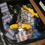
Unfortunately, the welder wasn’t quite user friendly yet.  I burned some more of the precious time before the birthday deadline updating it with a foot pedal and MOSFET charger disconnect.  Details in a separate post, but bottom line is it works fine and is pleasant to use in “production”.
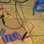
Testing of the candidate strings was tedious without my 16 channel recorder.  I’d let it run a while until terminal voltage indicated a couple of cells had gone to zero V, then manually measure voltage on each cell.  Since these cells were at least fair, when one died I shorted it out with a clip lead, reasoning that shorted is less damaging than reverse charging.  Then wait for next cell or two to go flat.  With interim string terminal voltage in a spreadsheet, formulas using load resistance and sample times gave me approximate A-hr capacity of each group of cells.  A fan on the 4.7 and  6.8ohm 10W load resistors kept them cooler.
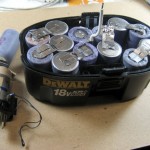
Looked at the numbers, made tough decisions, and came up with the final 15 cells.  The weakest links are probably only around 1.3A-hr (instead of 1.5), but now I can start final assembly.  Plopped a bunch of dead cells (I have a lot) into a case (I have several) to think about how to string ’em together so the first and last cells are in the correct position and all the polarities are right.  Worked with the rag tag bunch of final cells, reusing many old tabs.  By clever positioning and good luck, I ended up not having to put any new tabs in.  I used the case to hold the cells in position as I welded first the top tabs then the bottom ones.  The welding went without a hitch.
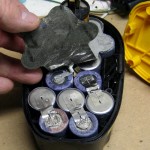
I put the adhesive backed fiber sheets on (hiding the functional, but ugly tab rewelds), soldered the last wire to the connector, and it was about ready!  The case even went together smoothly.
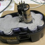
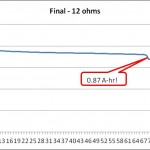
Charged a couple cycles (since some cells were fully charged when I assembled the pack and others were not) and ran a discharge test.  The Craftsman-logged data tells a bad story.  I really think all the cells that went in were at least good for 1.3A-hr, so the results are a big surprise.  I’ll run a couple more charge cycles and then soak the whole thing at maybe 200 mA for a long time.  I hope that will normalize things and we’ll get better performance in the next test.  Unfortunately, it’s already Saturday morning…
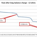
Later that morning…  I did another discharge test after what I thought was a suitable balancing charge over night.  The result was worse than the last one.  The first cell dropped at 0.5A-hr, and four had failed by 1A-hr.  Guess I better take it back apart 🙁

Later that afternoon…  I decided to go with Plan B.  I happened to have 15 new Tenergy sub-C cells I stocked for just such emergencies.  So I built up a whole new battery with brand new cells.
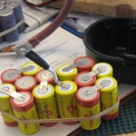
I guess I got those cells before the tab welder was working, because I seem to have sprung for tabs on all of them.  Unfortunately, the tabs are lighter (.008×0.275″) than the DeWalts, but I closed my eyes and decided to save a little trouble and keep the factory Tenergy tabs.  I hope that won’t turn out to be a mistake.  I pulled half the tabs off (all the negative sides, with consideration for the special terminations on the end two cells) and laid out the new battery.  I triple checked the layout, and didn’t end up with any mistakes.

As I started welding, it finally dawned on me why both DeWalt and Tenergy split the tabs to be welded:  For a two-at-once spot weld, the current path is from electrode to tab, thru tab to battery (first weld), across to other weld site, up from battery to tab (second weld), then out the electrode.  But without the split, there’s a pretty good path through the tab, without going through the weld spots and the battery plate!  Yeah, the higher resistivity of the nickel tabs makes that path higher resistance, but if you split the tab and put one electrode on each side, the path through the tab is MUCH longer – down one side of the split and back up the other.  Duh.  So I made splits in the Tenergy tabs (which were designed with just a hole for soldering) with a cutoff wheel in a Dremel.  I don’t know how much it helped the welds (and how much the loss of material hurt the high currents in real use), but I felt better about them.
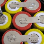
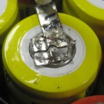
Here are some of the welds after I started splitting the tabs.  You can tell which ends were mine 🙂
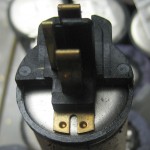
The real problems were the two end cells and how they connected to the connector.  The cell with the negative end lives in the tower.  The actual heavy copper strip the drill and charger touch is directly welded to the negative end of the cell.  I wasn’t confident my welder could handle material that thick, but I tried.  I did single welds, with the other electrode directly on the battery case so all the energy would go into one weld.  I also ran the cap voltage up to 16V (others had been at 15 or a little less).  After six welds, I inspected it.  It fell apart in my hand.  So I was right:  my welder can’t handle that!
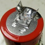
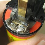
I knew I could weld regular tab material to the battery, so I made up a custom tab that would fit up around the original copper tabs.  Then I fitted the external connector over it.  I folded both tabs over, and having pre-tinned all surfaces, sweated them together.  I’m pretty happy with the result – I think it’s as good as the original (if different).
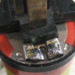
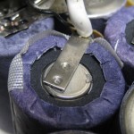
 

The positive end cell also has a thick metal piece (to which a piece of heavy wire is soldered), and I feared my welder couldn’t handle that one, either.  But after I made about 6 single welds and tested it, it seemed OK (though I didn’t try as hard as I should have to break it.)  But given the success of using some regular tab material for the negative end, I thought the least I could do was beef up the fat tab with some normal stuff.  It’s ugly, but it certainly can’t hurt!

Putting it in the case went pretty smoothly.  Although those cells had to have sat on my shelf for at least a year, before the first charge the terminal voltage of the pack was over 17V, and when I put it into a drill, the drill spun quite well.  That’s pretty encouraging.  I ran one normal charge cycle on a DeWalt charger and hooked it up for my now standard discharge test.  We’ll know soon.

A little later:  Success!  Looks like the cells are really well matched, and hit 15V at 1.9A-hr.  Woo hoo!


Posted in Battery Rebuilding | 2 Comments

Making your own printed circuit boards at Maker Faire

I’ll be running a booth at Maker Faire Northside Chicago April 21, 2012.  This post will provide a little info about it.

Rats.  I’m out of town that weekend.  I just wrote Christina to cancel the booth I just submitted a proposal for.  Boo.

Update 7/21/12:  OK, I’ve signed up to do the demos at the Evanston Mini Maker Faire!


Posted in PCB Etching | Leave a comment

Eric fixed the bad board!

At the space Thursday evening 3/8 I hauled the display out to see if I could address what looked like lack of +5 to the 4th latch board from left.  I reheated the +5V bus to that board, but the bad latching and dim display remained unchanged.

Gingerly putting a meter probe on the Vcc pin (pin 11, at the very bottom of the board – thanks, Murphy), I found there was no solid +5 there.  We discussed the unpleasant but doable prospect of cutting all the bus lines and pulling the board out to resolder that pin.  But Eric said boldly “I can fix that!”.  After maybe 4 unsuccessful attempts at resoldering the pin, he resorted to soldering a new wire to the pin and running it to the +5 bus.  It worked!

How he managed to solder a wire on the pin when he couldn’t solder it to the pad it was sitting on escapes me, but he did it.  While not elegant, his new brown wire is in keeping with the current ugly wiring style of the display, and it accomplished the task without having to pull the board – so it’s a win.  Thanks, Eric!

There’s still some funny artifact after each scroll (see clip at right), but that’s almost certainly just a coding error, not a hardware problem.

Posted in Scrolling LED | 1 Comment

First “production” recorder

A dance weekend finally inspired me to actually get the first model of the “final” design put together.  It’s almost all SMT (including a thru hole 3914 with its legs bent under), so I soldered most of the components on the reflow hotplate.  There was a little solder wick cleanup of the 0.5mm pitch 2167 AGC IC, but it was otherwise pretty good.  Custom prepping the parts – particularly the LEDs and the 3914 – took long enough that making several will be more of a task than I’d like.  The fixed resistors for the 3914 hi and low reference voltages hit quite close to the design targets.  I’m glad I laid out the board for 2 resistors in series for each so I could get close to ideal resistances.

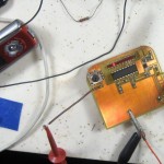
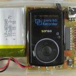
I’ve watched 3914 LEDs from a 2167 averaging cap and listened to the AGC behavior enough that running an audio source into the device, connecting the output to an amp and speakers and playing with the levels gives me a very good idea of how well it works.   Here’s a pic of the first bench test of the electronics – and it works!

There had been a problem with record level in the Sansa, but I finally got a version of the Rockbox software with the problems resolved and changed several defaults to fit my picture of the ideal device.  It comes up recording MP3 at 96Kb/sec 44.1KHz, creating  reasonable filenames, and boots up directly to recording mode.  It has threshold levels and timeouts all set up for the intended recording, and even shows a custom logo on boot.  I’ve built the code for Clip V1 and V2 as well as for Clip+.  That covers the models I find on Ebay.  The build machine is my Dell Mini9 netbook running Ubuntu 10.4.

Putting the firmware on is usually very straightforward, but I did brick one device trying to install Rockbox.  I might have to hack a JTAG connection in to get that one back.  Fortunately I have a few spares from a purchase binge on Ebay.

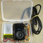
Here’s a closeup of the device.  While the electronics work fine, there were two mechanical issues I failed to anticipate.  First, the input level control obscures access to the headphone jack in the upper right corner.  Rotating the level control 90° and moving the recorder as low as I possibly can might make it accessible, but I’m not sure.

Second, and more critical, the Sansa sits so low in the box that any normal USB cable is very uncomfortably jammed against the battery.  I have room in the box for the recorder to sit higher, so I remounted it (after I’d soldered it down and used way too much hot melt holding the recorder to the PCB).  MUCH better.  One other minor mechanical hack was to carve away the slide switch on the side so I could hook a fingernail under it to turn it on and off more easily.

Using some solid #20 (or so) wire on the little PCB inside the Sansa for the external connections (V+, gnd, mic lead) works very well.  Easy to bend and to solder to the PCB.

I used some of my new Great Planes servo tape to mount both the PCB and the battery to the bottom of the case.  When I had to remove the PCB (to separate the excessive hot melt to raise the recorder) the servo tape held very well, but did finally release cleanly as advertised.  Nice stuff.

I had the first failure with the internal mods to a Sansa.  The input line just didn’t work.  It didn’t have the expected 2.5V I need to turn on the MOSFET that powers the electronics, and didn’t even seem to work for recording.  I took it all back apart and all the soldering of the mic lead looked fine.  That was on a nice Clip+, making it useless for this purpose.  Maybe I can rework it into the bench audio source I’ve wanted for a long time.

I applied the mods to another Sansa, and it worked fine – including using the 2.5V DC intended for the electret mic to turn on the MOSFET to power the electronics without a separate power switch.  (Interestingly, Les reported blowing a recording with an older prototype by forgetting to turn that switch on.  Maybe automating it will save me (or other users of the production version) from the same problem.)

I hoped to be able to see the LEDs through the side of the case so I could make a quick sanity check without walking up on to the stage.  I can sort of see them, but it could be a lot better.  Maybe a clear window in the side of the case and a plastic mirror over the LEDs at 45° to direct more light out the side?

I’ve used it for one night’s recording at the weekend so far, and it looks good.  The recorded level is almost too high – averaging around -12dB, though peaks are never over ~85%.  Looking at the recorded waveform in Goldwave, there’s much less dynamic range than I usually see – like the AGC is too effective/aggressive.  It sounds very good, and might even be a little easier to dance to the very uniform level, but it just looks different from what I’m used to.  I suppose I should arrange for a non-AGC parallel recording to see how much different it sounds.  I did set the compression resistor on the 2167 to about the max, so if I don’t like the sound I could tweak the compression down on future builds.

Update 3/5/12:  Here are some thoughts/concerns after having used the recorder once at a weekend.
– Access to the USB connector is workable but not great.
– Access to the headphone jack is blocked on the current version.
– Visibility of the LEDs from the edge would be very welcome.
– Routing of the input cable could use more thought.
– There’s considerably more interest in this than I expected, so ‘manufacturing’ considerations now start to matter.
– A little faceplate atop the pot body that could be marked for a few favorite levels would be good.
– Compression level needs to be reconsidered.
– The 3914 goes out of calibration at about 3.0V, so it may give incorrect indications at the end of the battery life, even if the electronics and recorder are OK.
– Need to finish up the doc!
– The slide power button on the Clip is awkward to use.  I should build it up or cut part of it back to make it easier to slide up.  Not a biggie, but would help, especially if user had big fingers.

Physical layout

It looks like I can get boards made up double sided, drilled, solder masked, 1 side silk screened for $1 ea plus shipping if I can keep the size to 5cm x 5cm.  At that rate it’s hardly worth my making them.  That way I can hand solder the 3914 DIP as thru-hole instead of bending the legs and doing it SMT.  And the pot is thru hole anyway.  I suppose I could even use 3mm LEDs thru-hole pointing out the side of the case to make them more visible that way.

The one downside is the pot.  The current board is 6.4cm tall, so using a 5cm board would move the pot down from its “protected” spot in the top corner unless I located the board at the top of the case – making soldering the leads for the recorder harder.  Hmm – I suppose I could have them come out the back of the Sansa case and mount it thru-hole.  Hmm.

The USB connector remains a concern.  Depending on the size of the outside of the connector being used, if I moved the Sansa absolutely as high as I can in the case (touching the top edge) and mounted the battery at the very bottom of the case the connector might fit above the battery.  That would leave the battery leads cramped, but might be OK.

Moving the Sansa up might make access to the power button on the top edge of the Clip+ a little hard, though relieving a lip on the case might help.  I’d really like to keep the option of using both Clip and Clip+ to ease access to used recorders.

The last consideration for the USB connector is that since moderate force is needed on insertion, physical mounting of the Sansa to the PCB and the PCB to the case needs to be pretty robust.  Servo tape seems good for the latter, and generous hot melt is probably OK for the Sansa-PCB.  I really should put something in the directions about pushing against the Sansa, not the case when plugging in a USB cable.

Access to the headphone jack is a conundrum.  Even if rotating the pot and moving the Sansa as far down as possible would provide access the jack, that would completely defeat any effort to make the USB connector more accessible.  And since at least in normal usage, the headphone jack is never used and the USB connector is used daily, the jack loses that fight.  But as long as it’s there, it would be nice to design so it could be used.  If I move the Sansa as far up as possible (to help with the USB connector) and especially if I only have a 5cm tall board, I could mount the pot low enough that the jack would be accessible.  But I’ve put protecting that pot pretty high on the list of objectives, and moving it down would make it less protected.  Darn tradeoffs.

Compression level

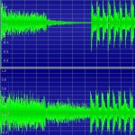
On all the recent AGC boards, I’ve used a 100K resistor to set the 2167 compression pretty high – between 5:1 and 10:1.  I figured more is better in the interest of making the device deal gracefully with a wide range of input levels.  Looking at the recorded signal from the latest board scared me a little because it looked so devoid of dynamics.  I did a quick test to look at (and listen to) music I’m familiar with recorded with and without the latest high compression.  Here’s several seconds’ worth of Blue Boys Da Ba Dee with an explosion that fades to nothing.  Top is recorded with the compression resistor shorted (1:1 compression); bottom at 100K.

It looks way different – both the lack of fade out and the lack of spike on downbeats after the beat resumes.  The fade sounds quite different, especially when it doesn’t go away at the end.  During the last part of the fade, I can hear background hiss come up as the AGC cranks the gain way up, but I had to listen carefully several times before I noticed it.  I guessed I’d hear the missing spikes – maybe a cymbal hit or something? – but after several A-B listenings I couldn’t hear any significant difference.

Part of the question is whether we’re recording in the “limiting” area.  Going below noise gate is obvious – it goes silent.  But the when you go above the “rotation” point (into limiting) it’s not so obvious.  I made another recording with compression with the level set lower so the fade out fell below the noise gate at the end, hoping that would keep us out of limiting, and possibly put the spikes back in after the fade out.  But there was no visible difference there.  Again, I couldn’t tell the difference among the three recordings in the section after the beat came back.

So maybe I’m just being paranoid, but I really care about the audio quality of the recordings.  The older AGC boards produced superb recordings, and these are different.  I think I have things set up to do a dual recording of a live dance tonight.  I’ll look at and listen to that pretty critically, and hope to come up with some science behind whatever decisions I make about the compression level in the next round of boards.

Update 3/20/12: The reorder has returned from its first mission not in my hands.  Janet took it to record at a weekend we didn’t attend.

Recordings varied from fine to unusable.  The bad ones ran afoul of the noise gate.  I don’t know how the LEDs looked for those, but maybe I should raise the level of the lowest LED so the noise gate is even farther below that point.

Recording level was generally perfect, but some just sounded kind of muddy.  I suspect those were running into limiting.  Maybe I should lower the level at the top LED to reduce that.  It would make level setting more sensitive, but if it produced better recordings, I guess that would be OK.  Gee, I wonder if the Sansa recorder is just really not quite as good as the Iriver.  That would be very unfortunate.  Maybe I should do some careful comparison testing (without any 2167s in the path).


Posted in Recording preamp/limiter | Leave a comment

Balloon + coffee + vacuum gripper

I’d watched with interest some clips of using a vacuum to “solidify” dry coffee grounds in a balloon to effect a robotic gripper, but was finally inspired to actually try to make one as an assistant counselor for a Robotics merit badge at Merit Badge University on 2/25/12.

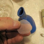
I found some heavy duty balloons at a local hobby shop marketed as waterproof bags for radios for RC planes.  (Who’da thunk it?)  At maybe 2″ diameter barely inflated, they were a little smaller than ideal, but that was what I could get on short notice.

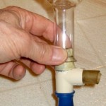
The first question was how to fill an inflated balloon?  (Actually this is the wrong question:  If you have to inflate it to get the amount of coffee you want inside, the balloon is probably too small.)  I found a T fitting that would fit the neck of the balloon and the neck of a small flask (with the help of some masking tape).  I put “enough” coffee in the flask, and stoppered it with the T – balloon upwards.  Using the third leg of the T, I inflated the balloon suitably (obviously pressurizing the flask at the same time).  Holding my thumb over the leg I’d blown into, I inverted the whole thing and let the coffee pour into the balloon.  Worked fine.

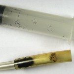
Now – how to keep the coffee grounds out of the vacuum source (whatever that might be…)?  First try was a filter to set over the grounds near the mouth of the balloon.  I found some near perfect very open, fine net in the sewing room scrap pile.  (Might be tulle?)  After a few failed tries at poking the stuff into the neck of the balloon, I gave up – with greater respect for ship-in-a-bottle builders.  Somebody mentioned a cotton ball, so I stuffed one of those into the balloon.  That wasn’t a great idea, either.  There’s much too much movement in the balloon to keep anything aligned with the bit of tubing going through the neck.

Final approach (how come it’s always the last thing you try?) was to just stuff the cotton ball into the tubing before putting it into the balloon.  Worked fine.  Final pressure control (positive and negative wrt atmospheric) was a large syringe that just fit the fat tubing I was using.

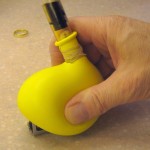
For my setup (which included an overfilled balloon), best results were when I pumped maybe 1/2 fl oz of air into the balloon to make it nice and soft so I could squish it firmly around the object to be gripped, then pull the plunger back to solidify the coffee.  There’s obviously no actual squeezing of the object from the hardened coffee, but with the sort of sticky balloon surface, it would hold a 9V battery quite nicely.  Picking up something like a pen where the balloon could actually get a little bit underneath the object produced better holding.  Pushing the plunger back in to let the object drop on the table usually got applause from the scouts watching.  Sorry for no pic of that – the balloons were all broken before I got a shot.

All in all a fun exercise.  Some thoughts:  Get a good sized balloon (obviously not mylar!).  You have to push the balloon down to very significantly surround the object to be picked up.  The 2 oz syringe I used worked fine for my small balloon.  Of course use heavy wall tubing so it doesn’t collapse.  Since you have to manually surround the object with the balloon, a surgical glove might be an interesting alternative to a spherical balloon.

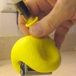
Update 3/2/12:  I got a package of twenty 12″ balloons at a party store and brought all the stuff to W88 Thursday.  I didn’t have time to build anything up before hand, so I assembled one on the table at the space.  It worked fine.  Here’s the balloon being pushed down around the pickup target.  Note that it’s not particularly being squeezed against the target – just pushed down to provide lots of surface contact.

Here’s a successful pickup.  But even an unsuccessful pickup leaves a very clear impression of the target.  Something like a fat pen that the balloon can fit a little around and under is an ideal target.  You do have to squeeze a little to get the grabber around underneath.


Posted in Robotics | 6 Comments

Bluetooth module breakout

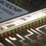
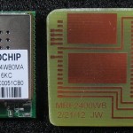
This is just a quickie to provide a way to connect to a Bluetooth module for Russ’ chording keyboard.  I found a datasheet and an Eagle lib with the footprint.  Unfortunately the pads didn’t provide enough area outside the “half via” connections at the edge of the module to solder them by hand.  Fortunately, I’ve made enough peace with Eagle that it wasn’t hard to hack the footprint (adding a new package variant) with some top layer rectangles to extend the pads a little.

To use the module on a breadboard, it made sense to break all the interesting leads out to a 0.1″ male header on one side – leaving the board and module hanging out in space over the side of the breadboard.  The pins should provide enough mechanical support for breadboard use.  I considered adding names next to each pin, but that would have extended the board enough to cover many breadboard holes.

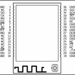
I think I got all the important leads, but here’s the pinout for the record.  I also (think I) brought out all the JTAG leads to little pads so in the unlikely event of need for such debugging there’s at least a little something to solder to.

I hope it works out!

Posted in Miscellaneous, Workshop 88 Stuff | 3 Comments