I’m dragging my feet on making up the final boards for the ‘production’ Sansa recording devices. Much of it is that I don’t really trust the new ones. I think I heard some distortion in some of the Sansa recordings some time, and I’m afraid I got too greedy and set the compression level too high. It has spooked me so much that I don’t even use the latest prototype for live recordings – I still use my old faithful white box / Iriver 890.
That final size (smaller) device has the resistor that sets the compression level buried under the now-glued-in Sansa. I’m torn whether to rip it apart and change the resistor or just use the new resistor in subsequent instances.
More troubling is the distortion I seem to recall. It’s (obviously) either in the AGC/limiter electronics or in the recorder itself. Since the 2167 implements a fairly hard limiter at the highest levels, it’s possible the problem came from that.
To test for distortion at high levels, I wanted to drive the electronics with a fairly high level signal, pick off the audio just before it goes into the Sansa and run that to a decent amp and speaker. By listening closely as I adjusted the level control on the PCB (and using the LEDs as a level indication), I hoped to be able to hear any bad behavior at high levels.
I first tried to use the one remaining larger prototype, since the Sansa is socketed and it would be easy to change the compression resistor. After various attempts, I’m afraid that one is dead. There’s no audio out, and the averaging cap always has ~4V across it. I can see audio coming into the 2167, so it’s good that far. The top of the averaging cap is the DC level that runs the 3914 and LEDs. In that old larger prototype, that signal goes through some CMOS switches intended to allow the LEDs to also show battery level. (I ripped all that out in later smaller versions, and just use the battery gauge in the Sansa.) But if any of that was bad, it could conceivably inject some DC onto that cap. But when I cut the trace from the cap to the rest of the world (leaving the cap connected only to the 2167), the voltage remained unchanged. Looks like the 2167 is dead. Bummer.
Brief detour to make a tool
OK, I’ll use the little one. And its high compression should help show any distortion at high levels. First thing is to drive it with some high quality music I know well. I’ve put a suitable collection of music on one of the old Irivers, and that’s now my usual audio test source. Hook it up and try it. Everything sounds fine – but even with the Iriver’s volume cranked all the way up, I can’t even light the top couple of LEDs. I’ve been aware of that shortcoming for some time, and I think it was what drove me to dig out the old 386 amp that inspired the “What a difference 30 years makes!” post. But I still don’t have a dedicated amp to give me more signal.
I scrounged around and found a little dual-386 amp that drove the non-powered speakers on my desk at work for the last couple of years there. But I needed that to run the output of the AGC/limiter to speakers to hear it. If I had another one of those, that would be about ideal: Gain of 20, and low enough output impedance to drive speakers should the need arise. <digs around some more> And in a great stroke of looking forward, I even made a spare board when I made the one for my desk!
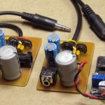 I drilled the board, found parts, and made up a new copy of the amp. While the original had a coax barrel connector for power from a wall wart, I wanted this one to be portable. To get good voltage swing, I needed around 12V, but didn’t want to mess with a 12V battery. I found a DC-DC boost converter from another project that takes anything from 3.5V up and makes anything up to around 40V. I’ll power it from 3 AAs. Might make sense to leave regular alkalines in it so it will work when I need it, but pop some Ni-MH cells in if it will be used heavily for a while.
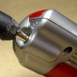 As is my custom, I put a pigtail on the new amp for the input lead (avoids the possibility of a flaky connector). Unfortunately, the cable I grabbed to cut up had a big honking plug that wouldn’t fit in the unusually narrow headphone jack entry on the Iriver. A little hacking relieved the plug and did the trick. Yeah, it’s ugly – but it fits. I have the tool – now I can do the testing I started out to do: crank the level up and see if I can hear distortion.
Looking for distortion
I had done something similar when I first set up the new electronics. I played with it, watching the LEDs as I decreased the level down to the noise gate, and set the 3914’s RefLo voltage so if even the bottom LED was on, it was still above the noise gate. I’d tried to set RefHi so as long as it was below the top LED, there was little or no distortion.
This round of testing only confirmed that I’d done what I set out to do originally: If I cranked it up enough I could hear distortion – but I had to be above the top of the LED scale to do it. Hmm – that leaves the specter of the Sansa recorder being not as good as the Iriver – and maybe not up to the task of the high quality recording I want. That would be bad: I’m pretty heavily invested in this approach – and using the Sansa recorders. I just counted noses and I’ve collected 10 of them so far.
I think I did one round of A-B recording with my ‘good’ setup and a 2167/Sansa at the same dance. I’ll try to find that and do some critical listening.
Hmm – found two sets. One was white box/Iriver vs 2167/Sansa. But that was before I had firmware with appropriate levels, so the Sansa recordings were down by 2 bits (factor of 4, or 6dB). The other – from 3/5/12 – was 2 Sansas, one with no compression, other with 100K resistor -> high compression.
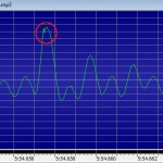 In listening to the latter, there were places with loud clear voice only, no music, where I can hear a little distortion. Clipping? Looking at the recordings in GoldWave, I could almost convince myself there was some of the peak folding that I think might be digital clipping. The period of the glitch in the circle (at 5:54.658 in R120305-195354.mp3) is 0.00007 sec, or a cycle of about 14.3KHz. There can certainly be any frequency components at any time, but there’s nothing else nearly that high in the neighborhood. The 2167 is all analog, so if it is a digital artifact, it’s the Sansa’s fault. Hmm – there’s a soft level control in the Sansa that I think controls an analog stage just before the A/D. While I set that so I never see recorded values at 100%, I wonder if backing it down a notch (which is 1.5dB) might reduce this distortion. Or, since I think I have more than 1.5dB headroom, if increasing it would increase how much of this occasional distortion I see (hear).
Sandie was using an MA-150 amp, which I expect is all analog, but as one of the latest bits of Hilton gear, I suppose it might somehow be digital. To rule out distortion from the Hilton, I found the same spot in the non-compressed recording. The spoken phrase sounds some different, as it has a large dynamic range, and the compressed version is pretty much all at the same recorded level, while the dynamics are audible (and visible in GoldWave) in the uncompressed version. But after tweaking the levels so they sound the same and doing repeated A-B playings of the two, the critical observation is: the uncompressed version sounds fine – the obvious distortion in the compressed version is just not there.
Guilty party?
So the distortion comes from either the 2167 electronics or the recording action in the Sansa. Which one?
The voltage controlled amp in the 2167 is known to introduce some audible distortion on peaks, due I believe to a design flaw. I think my hack of reducing the signal between the initial buffer amp and the VCA should avoid this distortion (at a cost of signal level). And I just did some careful listening audio testing (with the new dual 386 amp) picking audio up on the lead going into the Sansa, after the 2167. And even cranking the signal level through the 2167 way higher than it deserves to go, I heard little distortion, and certainly not as harsh distortion as I hear in the compressed recording I’ve been working with.
So that really sort of points to the recording hardware/firmware in the Sansa. I guess that defines the next test: Going through a 2167 with high compression (like the one small version I have), record to the Sansa but change the record gain up and down a bit. If I can recreate the distortion and it goes down/away at lower record levels, I’ll take it! The current record level hits peaks ~90% (-1dB), so I could certainly afford to take it down some. I’ll use the same block of Sandie’s voice I’ve been looking at above – from the uncompressed version, of course – for source material.
Hmm – not what I expected. My standard recorder gain is 0dB. I recorded at +1.5, 0, -1.5, -3dB. I clipped one phrase from the source and from recordings at -3 and +1.5dB and normalized the volume. Testing consisted of playing that 5 sec recording in a loop and trying to hear differences. The original sounds perfect; the other two are both distorted and as far as I can tell, indistinguishable. (“Everybody” is the most distorted word.) So a 4.5dB change in recording gain produced no audible difference. Doesn’t sound like a clipping problem in the recorder to me – unless it’s early in the audio path.
Improvements to the new device
That leaves the 2167 electronics. There are two possible problems.
First, I’m unhappy with the sound of the high compression. I don’t know that it’s causing distortion, but I don’t like it. Unfortunately, I have to tear the glued-in recorder out to get at the resistor that controls the compression.
A second possibility is an unjustified resistor value change I made in my hack to reduce distortion/increase headroom. The initial buffer amp is connected to the VCA by an external (10uF) capacitor. There’s an internal 1K resistor in series with the output of the first amp. My hack was to connect an external 1K to ground on one side of that external cap, cutting the signal in half. With that in place, the VCA produced much nicer sounding output.
In this version, I changed that external resistor from 1K to 1.5K, to give a little greater final output. I did that unilaterally, with no testing to verify that it still works OK. Of course that raises the signal level to the headroom-constrained VCA. Fortunately, that resistor is easily accessible. So one step in the next rounds of troubleshooting is to swap that out for a 1K or maybe even an 820Ω, having carefully made reproducible recordings before the swap.
Another step would be to cut the input level to the 2167. That would do almost the same thing as decreasing the level with the lower hack resistor value, giving the VCA less excuse to distort, at the cost of moving closer to the scary noise gate. But at least it’s an easy test 🙂
<testing…> I couldn’t hear any significant difference between two recordings including the distortable “everybody…”, one with the input level pot on the 2167 board set to about 40% of the other. But I guess that makes sense: While we had noticeably less signal going into the VCA, the AGC part would have cranked the gain control signal up to try to make up for it. And if the distortion occurs in the output section of the VCA (which is what has to handle the largest signals), we’d have almost the same levels in the two cases. And the actual recorded levels of 13.9 and 14.1dB support that. Oops – bad test. OK, OK, I’ll swap out the dumb 1.5K resistor. Since that’s after the AGC detector but still before the VCA, we really should get a smaller signal out – and maybe a less distorted one.
I was going to use an 820Ω, but since I didn’t have an SMT one I used a 1K. I couldn’t hear any significant difference between before/after recordings. I was surprised at how similar the recorded levels were – 14.7 v 13.9dB. But after I did the math – 1K/2K vs 1.5K/2.5K is 0.833 or 1.8dB. Close to the 1.2 I saw. So that change didn’t make much difference.
Hmm – what if the distortion is in the Sansa’s very input section? If it were before the recording gain control, changing the gain would not change anything – just as I observed!
There’s a 22K resistor between the output of the 2167 and the Sansa input I could use to further reduce the signal, but again I can’t get to it. Between that and the fact that I’ll never trust that device until I can get the compression down, I guess I’ll have to tear it apart. Humpf.
Tore it apart. The servo tape holding the PCB to the case held well, but released when I pried at it. The hot melt came off more easily than the last time, since I used less 🙂 I unsoldered the 3 wires to the Sansa, but they were loose: The hot melt holding the little PCB those wires are attached to inside had let go. Disassembling the Sansa had an additional benefit: The 4-way ring rocker switch was not seated correctly and didn’t work as smoothly as it originally did. When I pulled it all apart I was able to seat it correctly, so the buttons should work nicely now. Of course since I don’t use those buttons in normal operation, that doesn’t matter much.
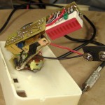 But I still don’t know what compression value to use. So I pulled my dear old “gold standard” white recording preamp apart and wrote down all the component values. The resistor that sets the compression ratio is 68K. From the 2165-1 doc, that should give a ratio of 5:1. Now I know what to shoot for! In the 2167, 5:1 is 75K. Like I have one of those lying around in 1206 size. I re-laid out the board for 2 resistors in series for the next rev. 68K+6.8K is real close. Now I need to replace one (100K) resistor with two on the existing board.
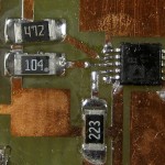
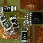 Done! I got lucky with the available space. A couple of cuts with an Xacto knife and I even had a chunk of isolated copper to make the junction. This shouldn’t affect the distortion, but it should make it sound a little better by not so aggressively cranking up the gain on the quiet parts.
I swapped the 1K “hack” resistor (had been 1.5K) for 680Ω to give myself a little more headroom in the VCA to possibly better cope with low supply voltage at the end of battery life. It will cut output level a little bit, too. But I’ll swap out the 22K in series with the 2167 output for a 33K to reduce the input to the Sansa more substantially. If I really was putting more into the Sansa input than it could handle, that should help.
After I put it back together, one of the first things I did was reset the Sansa’s clock so the timestamped file names would be correct. To do that I needed – the buttons on 4-way ring rocker switch. So I got a little quicker payback on that one than I expected.
To test it out, I made recordings with both the new box and my standard white box. The white box sounded fine, but to my amazement, the new box sounded as bad as ever, even showing no apparent change in the compression! WTH? I took both to a dance and made simultaneous recordings. In those live recordings, the ones made with the new box were virtually indistinguishable from the ones with the white box. That’s just what I hoped for, but flies in the face of the test made earlier the same day. What’s going on?
I redid the A-B bench test, but this time (like the live recordings, and matching my expectations) the recordings were almost indistinguishable. All I can imagine is that I made some clerical error – picked up a wrong file – that led to incorrect results from the first test. It’s pretty disconcerting when you design and perform a very simple test looking for very specific information, get the results (even though they weren’t the desired or expected outcome), and later upon redoing the test conclude that the first test was invalid, but for reasons you can’t explain. Boo.
But the good news is that now the new box works. I double-recorded another dance, and again, the results are almost indistinguishable. Treble on the new box might be slightly less bright than the white box/Iriver, but it’s good enough that I’m now willing to use the new box for recordings I care about, and now I can (finally!) proceed to commit the design to a production run! I never did find the source of the distortion I was after, but as long as it sounds good now, I’ll take it.
Update 5/20/12: I’ve used the newly tweaked device at three dances recently. All the recordings came out great. It even passed the test of recording from a Tape Record output on a Hilton 75A – one of the lowest level signals it’s supposed to work with. Indication was one or two LEDs lower than ideal, but the recording was still just fine. I’m finally really willing to use these guys in earnest and put my name on them for others. I still have to lay out a 5×5 cm board, re-find the board house that will do those for a buck, etc, etc. But at least the design is now sound.
