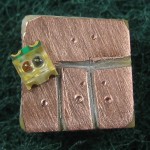
I wanted to use an SMT red-green LED for a demo board for the Tiny85 class, but for initial development I needed something breadboard friendly. Quicker than laying out and etching a real PCB for  something this simple, I just cut some insulating paths in a scrap of copper clad.
Holding some 0.1″ header against the board, I marked where to drill holes for the three pins with a scribe. I also marked where the solder pads of the LED would go (a little crookedly, it looks like), and used the marks to decide where to cut. A good technique for cutting away copper was two passes with an Xacto knife at angles to make a sort of V shaped groove.
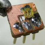
 After drilling I soldered the pins normally, but used my new friend solder paste for the SMT pads. I had to be careful locating the LED to make sure the two anode pads didn’t touch the wrong places, but after I did the solder paste helped a lot in holding it in place. You can see a little ding from the vice grips I used to hold it while drilling. Works fine. Another quickie success!
