Fixing B&D Cordless Broom

BackTogether9981I’ve used my 18V B&D cordless blower to clean grass clippings off the sidewalk after mowing for many years.  It’s great.  The 15 cell sub-C NiCd battery packs didn’t last for a whole cleanup – but I had two, rebuilt them, and limped along.  Then I hacked the nice 3.3 A-hr Li-ion pack in and it would run 2 or 3 cleanups between recharges.  Great!  (OK, and ugly.  But it works.)

Today it sputtered and died most of the way through the cleanup.  Grumble, get the Connector9983broom, grumble…  After sweeping up, I checked and there was in fact voltage at the connector into the blower.  (While the original plan was to fit the Li-ion into one of the old battery pack shells (though sticking out one end), all I ended up keeping was the connector from the old pack.  It’s connected to banana plugs that mate with the battery with a piece of 18-2 zip cord.  That wire’s not really big enough – it gets warm when the blower runs for more than a minute or so.)

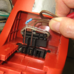
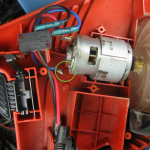
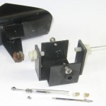
BrokenMotorTerminal9937Great – did running a motor designed for 18V NiCds on a hot 18.5V Li-ion burn out the brushes?  It’s noticeably louder (and higher pitched and more effective!) with the new battery.  So I took it apart, and the problem was immediately clear: One of the motor wires was disconnected.

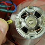
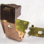
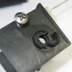
BrokenTerminal9938Worse:  The terminal going into the motor was broken off below the surface.  There’s really no way to fix that from the outside, and with the stamped/crimped construction of the motor, there was no simple way to take it apart.  Rats.

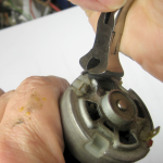
So the whole blower is now worthless.  The chances of finding a replacement motor for less than a large fraction of the cost of a new blower are about nil.  UncrimpingEnd9943With nothing to lose, I started trying to tear it apart in a way that might let me put it back together in case I figured out a way to actually fix that terminal.

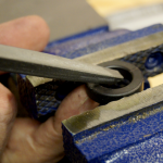
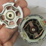
EndOff9949 The end of the motor shell is crimped around the end plate.  It’s steel and  bent away only grudgingly to some end nippers.  But bend it did, and the end plate (and bushing) came right out.

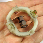
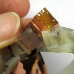
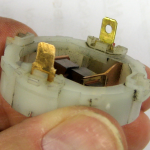
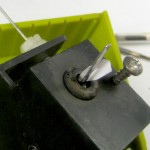
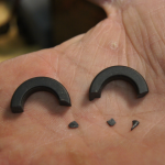
BrushHolderMinus1Terminal9951The remaining terminal is attached to a plastic brush holder ring.  HowBrushHolderFits9953That pulled right out, too.  The brass terminal piece  is riveted to the brush spring, and fits through a slot in the plastic ring.  There was so little surface area where the terminal was broken off that there was no hope of BrokenBrushHolder9957reattaching it short of brazing, which I wasn’t comfortable with and might have hurt the brush spring.

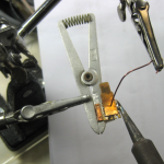
I decided to make an oversize new terminal out of some bronze? spring brass? strip I had and soft solder it to the remaining brass piece.  The strip was 0.015″ thick and the original terminal was SolderingNewTerminal99600.020″, but I guessed it would work if I smushed the female terminal a little.  Whether it ever gets hot enough to melt the solder is a good question.  I tinned both surfaces first, made a jig to hold them together and sweated them.  An aluminum clamp heat sink was there to try to protect the brush spring.

NewTerminal9964It was obviously thicker overall than the original, but to my surprise took only a little forcing to fit into the original slot.  Looks promising!

SolderOnFemales9959When I went to crush the female terminal to fit the thinner male, I was quite surprised to find solder blobs on both females.  I have no idea what that’s about.

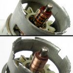
Almost there!  Now if I can just get it back together.  Well, not quite.  While I was pleasantly surprised at how much brush material remained, the commutator was kind of burned.  The brushes were interestingly shaped so each touched the commutator at 3 places (hence the 3 burn rings).  No good pic, Commutator9970but you can see the cross section of the out-of-focus brush in the foreground in the picture above of how the terminal fits in a slot in the plastic ring.

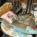
Anyway, a little emery cloth made the commutator at least look Recrimping9976prettier.  The brush holder and brushes slipped right in, along with the metal end plate.  Some creative placement on the anvil let me peen the crimped edges back over the end plate.  It came out pretty well.

I put it all back together, and it worked fine for a couple of minutes of cleaning up what the broom had missed on the grass clippings remaining after the blower failed.  We’ll see how it holds up over time, but I’m pretty hopeful that I’ll get a few more years out of it.

Posted in Home Repair, LiPo Conversions | Leave a comment

Dell laptop battery test / rebuild

My dear (7 year) old Dell Inspiron 700m with extra capacity 8 cell battery has been running out of battery more quickly than I think it used to.  Since Bob G recently bequeathed a couple of laptop batteries to me, and since both those and the Dell seem to use standard 18650 Li-ion cells, it occurred to me that maybe I could rebuild the Dell battery with the scavenged cells.

OK – first, are the new ones any good?  I popped one 2P3S battery open, hooked my nice programmable charger to the outside wires and charged it up.  (It’s comforting to have gone from “Ooh – lithium batteries are dangerous and require very specific charging techniques – I’m staying far away from those!” to “Oh, you can use about any Li charger for any battery as long as it’s for the right number of cells (in series) and less than maybe 1C 6cell+8cell9860charging current.”  And to have the programmable charger I got with my 3.3A-hr 5S Lipo pack.)  Then I ran a discharge test with my usual Arduino discharger.  Running down to 9.6V (3.2V/cell pair), it gave 3300 mA-hr at ~0.5A.  Not bad for a 4000 mA-hr pack.

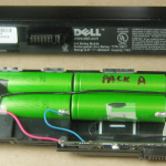
Here’s the 6 cell pack posing with the 8 cell Dell pack.  I bet those cells would just drop into the first 6 slots without even touching the tabs.

Second – what’s the actual capacity of my Dell battery?  That was tougher, since it’s my only good battery for my good laptop, and  I didn’t want to open it up unless/until I was confident I was going to rebuild it.  I took it out of the laptop (fully charged) and probed the connector, looking for nominal 14.4V.  Nothing.  Google indicated some of these batteries needed some pins shorted before they presented power on the connector pins.  I found similar pinouts, often putting V+ on two outside pins and V- on two pins at the opposite end of the connector.

Noisy battery / a lesson on hum

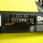
Unfortunately, I couldn’t find anything definitive on the connector pinout on this C6017 (similar to X5458, C7786, W5915, Y4546) battery, so I started to make measurements – first voltages between every pair and then continuity between pairs with 0V between.  I don’t know the real pin numbers, so I arbitrarily numbered them as shown in white in the picture below.  Sure enough, pins 1,2 were connected.  But there was no other pair solidly bonded.  The voltage readings were flaky, so I started to watch more closely.  Between some pins I saw random values changing between maybe 15 and 100 mV.  I made better connections to the battery connector so I wasn’t touching anything.  There was still too big a variation, so I started looking with a scope.

What I saw was hum – but only if the scope was connected certain ways.  If the scope ground were on pins 4 or 5, I saw hum on all the other pins.  But if the scope ground were on any other pin, 4 and 5 were quiet.  That was just weird.  The battery is in a plastic case, sitting on a formica/plywood bench completely isolated.  Nothing was referenced to anything.

Well, except capacitively.  I now suspect that 4 and 5 are the thermistor, electrically isolated from everything else.  The bulk of the battery – the cells and connected electronics – were large enough to be capacitively much more connected to the noisy electrical environment than the little wires to the thermistor.  If I connected scope ground to the flimsy thermistor, the rest of the battery made a good antenna to pick up hum.  The other way round, the thermistor was mostly cap coupled to the battery – which was then the ground reference.  That was what I was seeing with the DVM, too.  An interesting lesson in hum.

Bits!

The really serendipitous news was that the scope let me see that there was occasionally some much more organized noise.  I finally found a way to look at it, and found a half-second burst of clearly digital signals maybe every 30 seconds.  I’d read there was I2C or something as a data mechanism between the battery and the laptop.  Could the battery be polling the laptop and looking for a reply to turn its power pins on?  Hmm.  When powered off, the lappy has no power to run anything to answer the battery.  Maybe it just needs a loopback – 2 pins shorted – so it hears its own data coming back (or maybe stops hearing it come back).  Randomly shorting pins on my only good battery didn’t sound like a very good idea.  Someone had suggested using a 100 ohm resistor when trying to loop pins back.  That should be low enough to allow digital signals to work while probably not blowing anything out if misconnected.  But which pins?

OK – 1,2 are almost certainly one side of the battery.  Since most other pins showed small (maybe 5-8mV) negative voltage when referenced to 1,2, I guessed those two were battery plus.  4,5 were probably the thermistor, so not of interest here.  Web articles indicated battery terminals were usually at opposite ends of the connector.  And there was ~400 ohms between 7 (likely battery minus) and pin 3.  And pin 6 was the one with the data pulses.  The pulses were positive going with respect to all other pins (except 4,5).  If 1,2 really was the plus side, the only way to see more positive signals would be if the power switch (a mosfet?) were disconnecting the plus terminal and it was weakly connected to ground.  So I tried 100 ohms from 6 to 3.  And I got 15.6V between 1,2 and 7!

Is it real – can I draw current?  Hmm – 15V and 1K is 15mA.  With my voltmeter between 1,2 and 7 I tried an LED and 1K across the meter leads.  It lit (brightly)!  OK, 100 ohms would give 150mA.  Here’s a fat 47 ohm resistor lying on the bench.  300mA is a reasonable test, so I put that resistor across the meter leads.  The resistor got hot and the meter dropped a few mV.  I can draw current!  OK – is battery minus on 3 or 7?  With the meter on (1,2) and 3, I put the 47 ohms between 1,2 and 7.  The voltage between (1,2) and 3 dropped only the same few mV.  7 is definitely battery minus.

Ahh – the 400 ohms is probably the load for the loopback test.  Pin 6 is really a digital input, being driven through a moderately large resistor by the actual pulse output.  Maybe that 400 ohms is what we “short out” the data signal with to ground when a 0 ohm loopback is between 6 and 3.  Emboldened by that science, I shorted 3 and 6.  No smoke, and I still got power.  Woot!

Battery test

SpoofedConnector9847With ends of a suitable size wire bent to make comfortable contacts in pins 3 and 6 and the wire taped down, I made up some contacts for 1 and 7 out of 20 ga wire and connected it to my discharge DellBatteryDischargetester.  A 40 ohm load gave me 350mA, and I left it overnight. It gave 1365 mA-hr quitting at 14.07V, although I set the discharger for 12.4V.  It was clearly at least at the beginning of the knee.  Looks like the over-discharge protector kicked in.  Anyway, that’s pretty low capacity for a nominally 4800 mA-hr battery.

Can I charge it?

Although I don’t really need to charge this battery through my faked contacts, I would guess I could do so.  Balance charging Li-ion cells is de riguer, and I figured with all those contacts, that balancing would be done by the charger in the lappy.  But now that I know pretty much what all the pins do, and there aren’t any at the cell-connection voltages, I’m pretty confident the balancing is done by the circuitry in the battery.

So I set my programmable charger for 4S and 0.7A – well under 1C – and fired it up.  It charged for a few hours, but while the charger is set for 4.2V/cell, or 16.8V, it showed a circuit disconnect at about 15.6V.  Looks like the overcharge protector kicked in.  That’s an average of 3.9V/cell (pair).

Either the protection circuit is way conservative, or it’s reacting to a bad cell pair, or it’s implementing planned obsolescence.  I’ve read that some manufacturers program the (protection circuit of the) battery to disconnect permanently – read fail – after so much time or so many recharges or something, forcing users to buy new batteries (or do without), with the implication of whether the battery has any useful capacity or not.

Do I rebuild it?

It looks like my anectodal observations of decreasing battery life (based largely on how long I can edit square dance music sitting in the back of Ed’s van on the way to a dance weekend) are borne out by the measured low capacity of the Dell battery.

I can get a replacement on Ebay for under $25 – with a 2 year warranty (which is longer than the laptop is likely to be in daily service).  Yeah, the ones from legit dealers are more like $85, but at this point in the laptop’s life cycle, cheap is appropriate.

Or I can rebuild it from cells from the batteries from Bob.  They may not be new (or matched, since they’d come from multiple batteries), but they show twice the capacity of the old battery.  I can probably just drop in the first 6 of the 8 cells without doing anything but unsoldering the wires, and I have a tab welder for the last pair.  And if something bad happens or I get in over my head, I can have a new battery in a few days for 25 bucks.

Or I can limp along with the old one, possibly using that as part of the process of deciding when to get a new laptop.  I’ll post here what I decide to do.

Posted in Battery Rebuilding, LiPo Conversions | 3 Comments

Drill press squeak fixed!

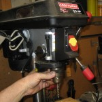
TurningChuck9818I think since the day I got it several years ago, my drill press has squeaked.  It happened – every time – when I turned the chuck by hand a little to orient the hole for the chuck key to a convenient place.  It’s fine when it’s running.

I couldn’t tell where it was coming from, but have tried a couple of times to make it stop – to no avail.  When it annoyed me today, I finally caught it.

I pulled the belt off the speed change pulleys, and (like always) turned the quill pulley by hand.  No noise.  But this time I turned the motor – and it squeaked!  Wow – it’s narrowed down!

But what’s squeaking?  I dribbled a little oil into the top bearing – no change.  Looking through the cooling slots near the bottom of the motor, I could see a mechanism – which turned out to be the centrifugal switch on this single phase motor – and that seemed the likely culprit.  I was temped to just spray some oil all over it, but I didn’t understand how it worked, and didn’t want oil on the actual contacts.

Google images provided lots of pictures, but none looked quite like mine.  Then I looked through the slots on the other side of the motor – and there were electrical contacts!  Now if I could see what was rubbing, I could lube it without getting oil on the contacts.

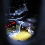
I finally divined that a disc was rubbing against a protrusion on the contact mechanism.  OiledSwitchActuator9815This was by design – it’s how the contact is operated.  I put a drop of oil on the end of a long scribe, carefully inserted it through a cooling slot and deposited the payload pretty accurately right where the disc and protrusion met.  I spun the motor back and forth a few times – and the squeak was gone!  The arrow points to a bit of shininess that’s probably oil at the critical spot.

That’s been bugging me for years.  Now the fix will come back and give me a little pleasure every time I use the drill press.  Excellent.

Posted in Home Repair | 8 Comments

Sump leak from new disharge line

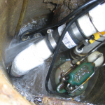
Spraying9673

video of leak

The morning after the first rain after installing a new sump discharge line, I was greeted with a loud water flow kind of noise.  It was a big leak, but thankfully (if amazingly!) confined within the sump, with no water escaping outside the sump.  The 13′ of new 1.5″ pipe provided about 1.3 gal of pumped-almost-out water to refill the sump through this leak for every sump cycle.

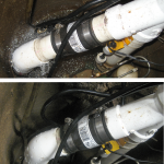
Apparently, the increased pressure from the longer, higher discharge run out to the front of the house – probably made worse by the hydraulic ram effect of the extra mass of water coming back when the check valve closed – “blew apart” the connection BeforeAfter9665between the main discharge line and the backup pump.  I pushed the two bits of pipe back into the flexible coupling and cranked the clamps down tight, and that seems to have fixed it.  Sorry for mismatched camera angles, but you can see how much less pipe is visible outside the coupling in the bottom shot after fixing it.

A scary side effect of pushing those pipes apart was that it also pushed the two pumps apart.  The main pump was jammed against the side of the sump instead of sitting more or less in the middle.  This movement could have jammed the float against the sump wall, preventing it from moving, resulting in a sump overflow (or possibly a continuously running pump).  Fortunately, the Zoeller pump designers included a guard ring around the float to prevent that problem.  It probably saved me from a wet basement.  Thanks, Zoeller!

Of course Murphy took advantage of my early morning uncaffeinated fogginess and provided the requisite fuck up of a 1.5″ diameter plume of water being pumped up at me from a not-yet-connected pipe.  While I had used the piece of coat hanger wire with a hook on the end that lives next to the sump (just for such uses) to pull up the float switch and drain the sump as much as I could before disconnecting the discharge line and lifting the pumps out, I missed the step of unplugging the sump power cable.  After I’d reconnected the backup pump and tightened the clamps on the rubber coupling down well, I lowered the assembly back into the sump – thinking I was almost done.  Of course the sump had refilled enough that the float switch triggered and the pump turned on while the pipe was still in my hands.  I did have the presence of mind to pull the sump pump plug before it pumped any more water out on the floor.  Yeah, yeah, I pulled it out by the cord instead of by the plug.  Under the circumstances I think that was a justified cheat.

NewClamp9675The one other surprise was the difficulty in disconnecting the pump from the new discharge pipe.  They were connected with the same piece of rubber sleeve that’s been connecting the series of sump pumps to the iron outlet pipe for the last 25 years.  It usually slips down the pump pipe fairly easily after the clamps are loosened.  But not this time.  I even started wondering if the guy who did the piping (not me) had glued the joint together!  (He had not.)  Recalling how hard it had been to disassemble, when I put it back together I used a shiny new (and looser) coupling.  (I’d laid in a stock of 1.5″ pipe fittings after a bad storm and dry well backup forced me to re-plumb the discharge pipe out a basement window.  I suppose I should write that up some time.)

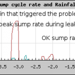
SumpCycleHistoryUpdate a little later: Here’s how the monitoring system caught the frequent sump pump cycling due to the leak, with the very visible drop to a more appropriate rate after the fix.

Posted in Home Repair | Leave a comment

Home page speedup

This has been annoying me for years, and is finally very much improved.

My home page would parse through the several megabytes of ascii sensor data to find the last typically 5 days’ data and generate the 5 graphs – every time it was called.  That guaranteed you were always looking at the latest data, but unfortunately that parsing/processing took on the order of 30 seconds, and it all had to happen before the page could be delivered and painted.  There must be a better way.

There is.  Fortunately, all the parsing and graph creation are neatly contained in one php file.  (Don’t say it.)  Now, the process on the Pogoplug here in the house that monitors the sensors and ftps the data up to the web host every 5 minutes does a wget on that php file (which returns nothing) right after it pushes new data up.  The home page no longer calls the graphing php, and now loads in seconds.  The graphs could be up to 5 minutes (plus the 30 sec php processing time) old, but they should always be the best available.  One could argue I should be kicking off the graphing script with an ssh instead of wget, but that’s harder.)

Unless, of course, something fails.  So just in case, the main page now checks the timestamps of all 5 graph files, and if they’re older than 300 seconds, it prints a warning.  I can always call the php script manually if I have to.

The bad news is that whenever I call the php graphing script, my browser (or wget) indicates that the connection has been reset by the other end.  Maybe the fact that nothing is returned is a problem?  I made up another php script that prints a trivial html page in addition to includeing the graphing php, just like the home page did originally.  That reports a reset as well.  So I can’t even put a refresh button on the home page to call the graphing script.  Oh well.  At least the home page loads fast now, and the wget seems to work reliably, so I shouldn’t have to call the graphing script by hand.

Update 3/27/12:  Did a little more poking around and have come to a couple of conclusions/observations:
– the web server times out an http request for a php page in about 15 seconds and resets the connection
– the php from such a request will continue running, though there seems to be a 300 sec max run time before the process is killed

I can’t get my old home page to work now.  If I include the graphing php script (just like I used to), the connection is reset.  I even went back and restored versions from a month ago, and same results.  It looks like the web server is timing out more aggressively than it used to.

Called GoDaddy support to ask if such a timeout had changed.  Got a pleasant but not heavily technical guy who had to go ask others a couple of times.  He said there had been no such change, but I don’t have a lot of confidence in that answer.

It’s not perfect, but it works, and I’ve spent enough time on it already.

Update 4/5/13:  Wow.  This round of updating the home page actually got me a working watchdog!  When I first put this up a few years ago I tried to set up a cron job to notify me if something was wrong – like the data file not getting updated.  But since they didn’t provide access to crontab, I put a fair amount of effort into a continuously running process to do the job.  Early ones failed, and I made self-respawning versions to circumvent max runtimes they seemed to reduce and reduce just to stop me.  I never wanted to duel with the sysadmins – just wanted some kind of watchdog.  Of course they won, and I gave up on my watchdog.

In this round of messing around, I noticed a cronjob manager in their web-based hosting control panel.  I tried it, and when it didn’t work, called the help desk.  They said they were doing maintenance on the servers so maybe that was why it didn’t work and I should give it a day or 2.  Yeah, right.  But sure enough, in a couple of days it started working!  Lots of testing later, I learned:
– my crontab file is in my root directory – one above html
– editing that file takes effect immediately and gives me complete control over cron jobs
– initial directory is my root – one above html
– */15 syntax in say minutes field will hit every 15 mins – I didn’t know that
– both stdout and stderr are emailed to user in MAILTO= line – didn’t know about stdout

Those tidbits plus a little hacking of my old perl script gave me precisely the watchdog I’ve wanted for years.  And by having the watchdog touch a file I was able to put a check on that file’s timestamp in the home page so it can flag when the watchdog fails.  Perfect!

I wonder if that crontab tool was there in the control panel – where it would never occur to me to look for it – from the beginning.

Update 4/8/13:  This doesn’t really belong here, but there’s no place else for it at the moment, so here goes…  As a backup/check on my rain gauge, there’s a nice professionally maintained one by the USGS on Salt Creek in Elmhurst maybe 2 miles away.  That  provides incremental rainfall in 1/100″ increments every 5 minutes – exactly as mine does.  While I put a link to its most recent graph right above my rain graph, sucking the data down and plotting it on the same graph as mine would be very nice.

There seem to be 2 servers with essentially the same info (as far as what I want), though their request syntaxes differ.  After some trial and error, here are some command lines that get the data and their results:

wget -O - 'http://waterdata.usgs.gov/il/nwis/uv?cb_00045=on&format=
rdb&period=5&site_no=05531300' 2>/dev/null >> raindata

USGS    05531300        2013-04-08 15:35        CST     0.00    P
USGS    05531300        2013-04-08 15:40        CST     0.00    P
USGS    05531300        2013-04-08 15:45        CST     0.00    P

wget -O - "http://waterservices.usgs.gov/nwis/iv/?format=rdb,1.0&
sites=USGS:05531300&period=P1D&parameterCd=00045" 2>/dev/null 
|grep "^USGS"|cut  --output-delimiter=, -f3,5 >> raindata2

2013-04-08 15:35,0.00
2013-04-08 15:40,0.00
2013-04-08 15:45,0.00

Running those from my shiny new cron capability, I see that (today) they both seem to make new data available in 20 minute chunks, posted just about 20 minutes in arrears.  The chunks are XX:10-25, XX:30-45, XX:50-XX+1:05, and are posted at about XX:45, XX:05, XX:25 respectively.  Setting my cron job for “6-59/20 * * * * <cmd>” got each new post today.  Making it “7-59/20” might be a little safer.

The way the graphing stuff works, I think I could put this data in a separate file, add to the current .php to parse it into a separate array, but then plot that data on the same plot area as my rain gauge data.  More work ahead.  (Spoiler, 6/26/19:  I finally got USGS rain data displayed alongside my rain collector’s data.  Long stories, but it seems to work!)

Update 6/1/13: After living with this for a couple of months, I can say it’s great.  No more slow page loading!

I put a trap in for stale graphs, and that has fired several times.  I think they’ve all been because the ISP ping stats graph has been stale.  And I think that’s because somebody hides that graph on the monitor page – and then the .png doesn’t get updated.  It took a couple of tries, but I think I finally got rid of any way anybody can turn that graph off, and since then I don’t think that stale graph warning has come up.

Anyway, it’s pretty good.  I still want to do a round robin database or something, but this is a big improvement.

Posted in Home Automation | 2 Comments

Oops

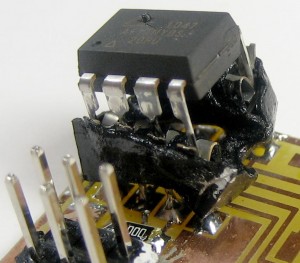
OopsBackwards9631While working on stuff for the upcoming Tiny85 class, I accidentally plugged one in backwards.  After I heard the little “poof” I unplugged it and tried to pry the chip out before I realized it had gotten hot enough that all the solder connections were still molten and the socket was coming out of the board.

You can see the spot on the top of the chip where all the magic smoke escaped.  You can maybe convince yourself you can see the pin-1-end notch in what’s left of the socket – and the pin 1 dimple on the chip.

I was trying to program the ’85 with an ArduinoISP at the time of the incident.  The good news is that both the Diavolino and the USB-serial cable powering it survived even after delivering enough power to do the damage shown.

Posted in Tiny 85 stuff | 2 Comments

Rain gauge repair

InPlace9543The rain gauge hardware out on the garage roof feeding info to my home automation system is pretty old.  It’s been in service I dunno – six years?, and on a shelf waiting to be installed for maybe 10 years before that.  It stopped working a few days ago.

It’s not a low-maintenance device, and fails a couple times a year.  Usually the small funnel tube from the big collector to the bucket counter inside clogs up.  (There are now 4 layers of screening above it, and it clogs much less often.)  So I (hauled out a short ladder, climbed up,) took it apart and looked at the tube:  Completely clean.

TippingBucket9547OK, as long as it was open, I flopped the tipping-bucket mechanism a few times by hand.  Seemed to move OK, so I put it all back together.  When I got in the house and looked at the Pogoplug that logs everything, I could see a couple of new counts from those manual flops.  Fine.

It rained some more, but it still didn’t register.  I opened it up again and looked more closely for binding, etc.  Looked good.  I flopped it a couple more times by hand and put it back together.  The Pogo noticed those flops.  But just to be sure water would actually tip the buckets, I went out and slowly poured about 50ml of water into it.  With its 8.7″ diam collector, that should be around 0.05″ – or 5 counts.  I could clearly hear the bucket flop about that many times.  But the Pogo didn’t see it.  WTH?

The next time I took it apart I almost gave up until I touched the metal contact coming out of the end of the reed switch – and it moved!  The glass reed switch was broken.  Rats.  But at least now there’s hope.

TakenApart9553I cut the soldered-on wires, took it all apart and brought the guts inside.  After (cleaning it up and) pulling the reed switch, it looked like this.  Fortunately, the reed switch drawer had an almost identical switch (but not broken 🙂 ).

DeadGrommet9556When I tried to remove one of the rubber grommets that held the switch, it just crumbled.  Not surprising.  I found another bit of rubber paperWedge9560that just fit the new switch and made a grommet out of it.  The one remaining (old, hard) grommet was slightly bigger than the switch tube, so I wedged a bit of card stock in for a better fit.  Picture was before pushing the switch fully into place.  Crude, but should last several more years.

Adjustment was touchy.  Fortunately, the nylon screws/locknuts let me move the bucket and attached magnet to just the right distance from the reed switch for what seemed like reliable operation.

Put it all back together, took it back apart to put in the parts I missed, and put it all back together.  I’d soldered some pigtails on the reed switch, and tied them to the original wires with very small wire nuts.  Maybe some time when the weather’s nice I’ll solder them, but they should be OK for now.

TestFromGround9562For a final test, (after taking the bottle with a hole in the bottom down, loosening the cap, and holding it up again) I drizzled water slowly into the collector and listened for a couple of bucket flops.  Back in the house, the Pogo saw them!  I think it’s fixed.

Posted in Home Automation, Home Repair | Leave a comment

AC line current sensing (and logging)

I’ve been interested in (cheap) AC current measurement/sensing for a few years now.  The first driver was wanting to add whole house energy usage to the home monitoring system.  (I even D+BEM100Bgot a Black & Decker EM100B strap-on electric meter reader on some deal site, but haven’t gotten around to decoding the protocol from its RF receiver yet.)  And I’d like the shop vacuum to turn on automatically when I fire up the belt sander, so sensing on/off would be good too.  (Yeah, I know you can buy them.  But what fun is that?)  I did use a surplus toroid from the junk box for a current sensor on the sump pump power line so the monitoring system knows when that fires, but couldn’t find a cheap reliable source for those coils for other projects.

I read up some on current transformers, hoping to put some split-ring version on each of the 2 very fat service phases coming into the house main AC distribution panel.  But while I found some openable cores, I’d have to wind those coils, too.  Toroids are really about an ideal core for the sensing/measurement applications I was looking at.  Update 1/24/18: A new “smart meter” installed a year or so ago includes an IR pulse per some unit of energy used that I hope to sense for quasi real-time power usage.

CoilWinderYouTubeI looked at the really cool toroid coil winding machines, but after I finally figured out how they work, it looked like they were too complex/precision to make for my infrequent uses.

The problem is threading the wire thru the closed loop of a toroid core.  I devised a topological cheat, and made a first prototype.  Then I tried the technique at W88 and Ti got some nice pics and videos of it, written up here.  Anyway, I now have a working wound toroid.

Signal amplifier

The cool thing about toroids for AC current sensing is that by just threading the (insulated!) current-carrying wire thru the core, it becomes a one-turn primary of a transformer.  (Loop it thru again and the output doubles.)  As with most transformers, our secondary sensing winding is completely electrically isolated from the AC line.

Unfortunately, with the 200 turns I wound on my first prototype toroid, I only had a few tens of millivolts with 0.5A (60W light bulb) thru one turn of primary.  Fortunately, since the output was going to a processor for logging, getting 5V to supply power to some electronics was no problem, so I could afford to add a small amplifier.

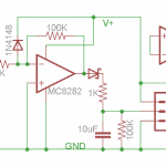
CurrentSensorSchematic500The MCP6282 dual rail-to-rail opamp has become my goto part for such things, with a (single) supply voltage range of 2.2-6V.  I only used one section, and basically boosted the small sine wave out of the coil to a rail-to-rail square wave.  Using a Shottky diode to SensorBoard9144rectify it provides as high a DC level out as possible.  The 1K in series with the output protects the opamp and allows it to drive an LED directly.  The 100K/10μF time constant determines how long after power turns off the logic signal remains high.  I put a 1uF decoupling cap across the supply for good measure.  The odd diode from the input to V+ is input protection.  There’s a clamp diode to ground on the chip, so between the two even some nasty spikes shouldn’t fry the opamp.

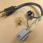
PluginAdapter9159For the proto coil, I soldered some wire from stranded CAT 5 cable to the real winding and secured it to provide more robust connection.  Here’s the coil and amp and a one-turn primary, ready to (be packaged up better to) sense when an appliance (my fridge) was running so the run times could be logged.  There are more details on the logging (and the fridge coil cleaning that inspired the logging) here.

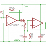
While this provides an acceptable signal for a fairly high impedance digital input on an Arduino, when I tried to run an LED with one as part of testing coils I wound at W88, the LED CurrentSensorSchematic4LEDflickered at 60Hz.  The 10μF cap wasn’t enough to keep the LED on solid.  Since one application is to drive the IR LED input of a solid state relay, and since there’s a second half of the MC6282, here’s a better schematic that should drive either an input pin or an LED.  I think I can drop the ugly 10μF cap down to 1μF by only loading it with a voltage follower using that second opamp.

For the real world, mounting the coil to the PCB would probably make sense.  That would make for a more robust assembly, and the coil wouldn’t need reinforced leads.

Transformerless power supply

For the SSR driver version, we don’t have low voltage DC available (but we don’t have any other possible references to ground/neutral, either).  Since there’s no exposed wiring, this might be a good application for a transformerless power supply using a cap TransformerlessSupply3to drop line voltage without dissipating any power.  I’ve never built one before, but the design is pretty straight forward.  Here’s my simplistic starting point:

The 0.47μF cap presents about 5.6KΩ of reactance at 60Hz.  At 120VAC, that would allow a maximum of about 20mA to flow.  Since the rectifier/cap only charge on every other half cycle, the max DC current it can supply is more like 10mA.  That’s perfect for running our 6282 and the LED in a SSR.  (I measured about 3mA of current through that LED at 5V.)

(Design sanity power check:  The zener keeps the voltage across (the diode and) the big cap to a max of ~5V.  It conducts in its forward direction on the half cycles the supply cap isn’t charging.  Thus it conducts ~20mA on the half cycles when the top wire is negative, and (20mA – DC output current) on the others.  Worst case (after the big cap is charged and no current is being drawn) it conducts 20mA on both half cycles.  With 5V across it one way and 0.7V the other, it must dissipate ~110mW – no problem for a half-watt zener.  So this whole supply should produce very little heat.)

Update 1/24/18: The transformerless supply above is really too simplistic.  While it’s fine to use a cap as the main voltage drop, there should be a series resistor at least to limit inrush current.  It would also be very appropriate to have an X or Y rated cap designed to fail open.  A fuse, or at least fusible resistor would be appropriate.  While I’m not going for X caps for a TL supply I’m designing into another project, and I couldn’t easily source fusible resistors, I did get some ~1A picofuses, which I’ll use.

 Putting it all together to make something useful

I breadboarded the supply, and it seems to work.  I just need to lay out a PCB with the supply, the updated signal amp and a place to mount (hot glue) the coil.

But while I was thinking about what size handy box I’d need to fit the PCB/coil, SSR, outlets and maybe some switches, some little sanity birdie whacked me upside the head, bringing me out of the OK-I-can-make-one-of-those-but-if-I-just-add-one-more-part-I could-make-it-do-even-more-cool-stuff death spiral.

The problem I was really trying to solve was eliminating the annoyance of having to make two motions to turn the belt sander on, then reach over to turn the vacuum on.  NewSwitches9270While a current sensor on the sander line would work fine, the real problem was that the two switches were a couple feet apart.  If the switches were right next to each other and could be operated in one motion like this ->, the problem would go away.  And I wouldn’t even have to make up a PCB or spend one of my $6 SSRs!

NewSwitchesInPlace9264A couple of handy boxes back to back for the switches, outlets and a power cord pigtail, and here it is installed and working.  Not the solution I expected when I started – but it fully meets the requirements.  (Well, except for the part about finding a good excuse to make the current sensor/SSR thing.)  I’m sure I’ll actually need a current sensed power switch for something else some day, and when I do I’ll have the design work already all done.

Update 6/15/13: Having used the twin-switch setup for a couple of months now, I have to say I love it.  Turning both on is trivial, and when I just need the vacuum, the switch is right there and easy to use.  I wish I’d done it years ago.

Posted in toroid winding | 7 Comments

Toroid winding (cheating method)

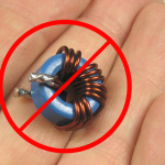
WimpyRfToroidNo9210Toroids with many turns of secondary winding are very useful for AC current sensing and measurement because you can just pass the wire carrying the current to be measured thru them.  (We’re not talking about coils with a couple of wimpy turns for RF – though those can be a good source of cores.)

But unless you can find a good, cheap source of well-wound toroids, you’re faced with the really unpleasant task of threading hundreds of turns of fine wire through that core.  (Well, unpleasant unless you have one of these cool toroid winding machines.  But I don’t.)

After I finally figured out how the machines work, I thought about building one.  But there are too many strange and precision parts, especially if you want to wind small cores – which I do.  So how do you quickly and simply wind wire on a closed loop toroid?

Cutting

Well, duh – you cheat.  If it’s good enough for Captain Kirk…  The idea is to cleanly split the toroid in half, wind it, then put it back together.  Yeah, it’s magnetically not quite as good after you glue it back together, but it’s good enough.

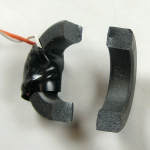
Fortunately, a ferrite core is kind of brittle, and if you score it nicely, it will often break fairly SawedPartWay9225cleanly.  I’ve tried a couple of different ways to score them, with varying results.  The first was to just saw halfway thru before cracking it.  (The material cuts very nicely with a hacksaw.)  That approach provided a nice break, but lost so much material that it really felt like performance of the core would be compromised.  (I never bothered to wind it.)
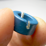

ScoringA6934In the spirit of scoring ScoringB6957plastic, I tried a Stanley knife.  It felt like it didn’t go deep enough to guide the break as much as I wanted.  A triangular file didn’t have any trouble cutting the material, but made a wider score than I wanted.  In any event, scoring the outside (and inside!) edges, as well as the flat side might help guide the break better.

CrackIt6938I generally held the core in a vise and whacked it to effect the SomeChips6942break.  Results varied from about perfect to needing some additional reassembly.
The material’s clean breaks make super glue appropriate.  By clamping the pieces together tightly, the gap OneChip6963should be small enough to not hurt the magnetic properties too much.  When there are chips, it may be easier to glue the chips back carefully as a separate step before you put the two halves back together.  If there are chips missing, abort and try a new core.  An air gap in the core is exactly what you DON’T want.
Winding

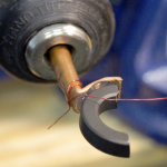
While you could wind the secondary by hand, my strong first choice would be to let SpindleAlignment6929a drill or something turn the core while I guide the wire.  We’ll need to attach some kind of spindle to the core to do that.  Most of the winding will be about midway between the two breaks, so that part should be on the centerline of the spindle to minimize wobbling.
You could use a dowel nicely shaped concave to fit up against the core as GluedOn6970the spindle, but the bottom would probably (underlap?) interfere with some of the windings.  Some copper or aluminum tubing lets you take advantage of the part of the core that won’t get any wire as a glue surface.  If you handle it gently while winding, hot melt is a great way to hold the spindle to the core half temporarily.
ReadyToStartWindingStill6972

Clip of live winding

It’s nice to know about how many turns you’ve put on so you can confidently make an identical one or vary the number of turns as you experiment.  Having a helper to count the turns is convenient.  Another, probably less accurate approach is using an estimate of the average diameter of one turn of the winding and the desired turn count to compute how much wire it will take.  Pre-measure the wire, and when you run out, you’re done.  In any event, chuck the spindle in a drill, tie off some wire so you’ll have a nice lead to work with and start winding!  Thanks to Ti Leggett at Workshop 88 for the video.  It’s also posted on the W88 blog.

Unlike with some fussy RF coils where you have to worry about losses distributed through the bulk of the core, it doesn’t really matter where on the core your secondary windings are.  Having them all bunched up together is fine.  But if you’d like to spread them out a little more (perhaps to leave more room for the primary wire in a very small core), it seems like if the drill/whatever is turning slowly enough, you should be able to move your wire-guiding hand back and forth in sync with the rotation such that the extended edges of the winding were neatly wrapped square around the core like the ones in the middle.  I’ve tried it, but with only very limited success.

Putting it back together
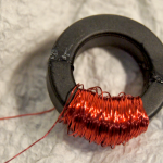
ToroidalAgain6977Super glue seems good because the breaks are clean and it introduces such a minimal gap at the joints.  Here’s a 1″ O.D. core wound with 200 turns of #30 magnet wire and glued back together.  Something like epoxy, that provides filler and some thickness to the glue joint would require that you clamp the core halves together quite tightly to squeeze out as much glue as possible.

If you’d like a little more physical strength and robustness – perhaps for a current transformer you were going to put around the main AC feed wires in your breaker panel – one possible approach would be to include a narrow zip tie on the outside of the core under the winding before you wind it.  After you glue the core halves together, bring the ends of the zip tie around the top of the core and pull it tight.  If you were quick, it could even provide clamping while the glue dried.  (Sorry – no picture.  I’ve never tried it.)

Now what?

You must have had some reason to wind that coil in the first place.  If it’s for a current transformer to measure AC current, you’ll need to terminate the secondary in a very low resistance, and figure some way to measure the secondary current.  You’ll probably also need to do some calculations (or at least testing) based on the material and dimensions of the core to see if it will stay linear (not saturate the core) over the current range of interest.

If you just need to sense AC current – for some kind of logging or perhaps automatically turning one device on when another is on, you can probably get away with most any small core.  Here’s a note on how I built an interface to an Arduino.

And if you wound wire on both halves of the core, you could make a more traditional transformer.  I’ve never tried that.

Good luck with your new toroid!

Update 2/14/13:  The W88 blog post made it to Hackaday!  The commentors there always keep people honest, and this was no exception.  One poster said he had broken cores several times, and there was no way to get the core back together tight enough.  He indicated his cores lost an order of magnitude in inductance!  I had no quantitative handle how much the gluing cost, but I didn’t think it would be that much. Time to try to measure the reduction I’m seeing.

I hand wound exactly 30 turns on one of the same cores (without breaking it first).  I tried a couple of indirect ways to measure the inductance, since I don’t have an inductance meter.  (I do have a capacitance meter, and tried using that both by switching the test leads and even by rotating the meter 180 degrees, but neither one worked.)

Extrapolating from the 30- to the 200-turn coil

The first thought was to measure the inductance of the intact 30 turn test toroid and compare it to the 200 turn glued-together toroid.  Since inductance is proportional to the square of the number of turns, I would expect the inductance of the big coil to be about (200/30)²=44.4 time that of the small coil.
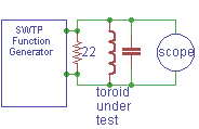
ToroidTest2I tried making a tank with a 47 nF cap in parallel with the coil, driving it with my dear old (old being an operative term) Southwest Technical Products function generator and looking at it with a scope.  (The 22 Ω across the generator output was to lower the output impedance from I think 75 Ω.)  I was going to use the known cap and the resonant frequencies to compute and compare the inductances of the large and small coils.  I aborted this after I realized this added a new variable of frequency, and I had no idea how the toroid material behavior changed with frequency.

Update:  The setup above is just wrong.  There should be some resistance in series with the tank to see the resonance clearly.  Thanks to M Peters for his comment below.

To eliminate the frequency variable, I found resonance with the large coil and 1 μF at just about 2 KHz.  I changed to the small coil and tried different cap values until I got resonance at 2 KHz again.  That was adding a 10 μF electrolytic across the 1 μF film cap for around 11 μF.  Plugging those values into a nice LC resonance calculator gives inductances of 570 μH for the small coil and 6300 for the large one.  That’s hardly the expected factor of 44, and using the test of a factor of √10, is in fact (barely) an order of magnitude off.  But the methodology was poor:  Twisting a knob and looking for a peak magnitude on a scope for a low-Q circuit is hardly precise.  And electrolytic caps have notoriously inaccurate values at best, and using them at zero volts is completely out of spec.  Next approach?

Apples and apples
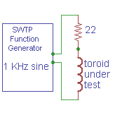
ToroidTest1aThe best approach would be to get something with the 30 turn coil I could measure with a decent meter, break and glue it, and measure again.  I put a nice carbon resistor in series with the coil, cranked the signal generator to 1 KHz, and measured the voltage across the resistor and the coil with a multimeter whose AC ranges were known good for that frequency.
30TurnTestToroidBreak9279I scored the coil with a jeweler’s file and broke it.  The break was one of the cleanest I’ve had (fortunately).  I used some old (read: thicker than expected) no name cyanoacrylate, wiggled the pieces to be sure they seated as well as possible, squeezed hard and put a spring clamp on it.  Then I put it back in the test circuit.

The break/glue happened over maybe 5 minutes, and the test setup was untouched, including the signal generator.  I measured the voltages across the resistor and coil again.  (Twice for each, as I had done the first time.)  This is about as clean a comparison as I can make.  So at 1 KHz with a 22 Ω resistor here are the results:

        Vres   Vcoil  Zcoil  L
Before  0.367  0.097  5.81Ω  925μH
After   0.372  0.068  4.02Ω  640μH

The inductance is reduced by the gluing by about 30%.  Quite noticeable, but quite acceptable for a hack.

I also did measurements of the tank circuit resonant frequency with the parallel combo of 10 μF electrolytic + 1 μF film caps before and after the break.  While there is a frequency difference, I’d guess it doesn’t contribute a large error.

       freq     L
Before 2.0 KHz  576μH
After  2.7 KHz  316μH

That test indicates a 45% decrease in inductance.  Not identical, but in the same ball park.  Now we have a rough quantitative handle on the impact of break/glue.
Posted in toroid winding | 17 Comments

Fridge coil cleaning and attendant yak shaving

While looking at dirty filter pictures for a future project to put a larger air filter in my furnace, I stumbled across an article about cleaning the main condenser coil under a refrigerator.  The before picture of the coil with the dust of the ages was gross; the after picture looked much more conducive to good air flow.

DirtyCoil9169Gee, I’ve never cleaned the coil in our 14 year old fridge.  I wonder how dirty it is?  <checks under fridge>  Eww, gross.  OK, guess I better clean it.

But the article had more:  There was a nice 2-line graph of electricity used before/after the cleaning, showing significantly reduced consumption after cleaning.  That’s cool – I bet I could do that, too!  Thus began the yak shaving.

Current sensor

Of course I couldn’t clean the coil until I had “before” power usage data.  To get that I needed a way to measure, or at least sense, the input current.  I have an amprobe clamp on current meter, but instantaneous reading isn’t really what I need.  I guessed what I’d see was shorter run times with the soon-to-be-more-efficient chiller.  So an on/off sensor I could log data from would be good.

One way to build an AC current sensor starts with a toroidal core with a winding (which will be the secondary) of many turns of fine wire.  Then the (typically thick) wire carrying the current to be sensed/measured is threaded thru the toroid, forming a one-turn primary.  For typical household devices, that wire might be 12 or 14 gauge.  If there’s room to wind a few more turns of the primary wire thru the core, the output is multiplied by the number of turns.

Unfortunately, I didn’t have such a device.  Fortunately, I had a bunch of appropriate ferrite cores.  Unfortunately, winding hundreds of turns of wire thru a toroid is a big hassle (though the machines that do it are really cool).  Fortunately, I had some ideas about how to wind a toroid mechanically (for some uses) without that magic spinning shuttle thing.  I’d never tried it, but this seemed like a good time to start.  And it worked 🙂

Unfortunately, the 200 turns I wound didn’t provide enough output to provide a reliable logic level I could log.  But since the coil would have to be fairly directly connected to some kind of processor, getting 5V to power some electronics to amplify the signal was easy.  A low power op amp, a couple of resistors, caps, and diodes later, I had something that would give a good logic level with a single turn primary carrying half an amp (a 60W light bulb).

PluginAdapter9159Here’s the coil, electronics, and some crude wiring.  A bunch of electrical tape later, I had a device I could plug into the outlet behind the fridge, plug the fridge into, and had a couple of feet of 3 conductor wire coming out to go to the logging device.  There are more details here.

Data logger

An Arduino was the obvious logging device, but I didn’t want to leave a laptop sitting in the middle of the kitchen for a couple of days, so I needed a standalone device.

Storage: I have some 64K byte serial EEPROMs, but would have had to make up a board to use them.  Hmm – the 328P has 1 KB EEPROM – would that be enough?  At say 2 samples/min and running for 2 days, that’s ~6000 samples.  I’ve only got 1024 bytes.  BUT – since the samples are binary – fridge on or off – I only need one bit per sample.  And I have 8192 bits.  Code’s a little uglier, but I can handle that.

Power:  An Arduino draws ~25 mA at 16MHz.  Two days would be ~1200 mA-hr.  Brand new NiMH AAs are ~2000 mA-hr, but the ones I have lying around are probably only around 1200.  Too close for comfort.  (And I’m too cheap to use alkalines if I can help it.)

Are there sleep modes?  <researches>  Yes!  And they only draw a couple of μA.  There’d still be bursts of activity, including a short LED blink, but with most of the time spent asleep, it should be OK on 4 used NiMH AAs.  A little more studying about sleep modes and how to wake up with a watchdog timer instead of an interrupt, and I was all set.  Well, after I also wrote code to dump EEPROM written bitwise, and figured out I’d have to clear the EEPROM with a separate sketch rather than in setup() of the logger sketch.  (If I didn’t do that I’d risk losing data before I could get the dumper running after the data was collected:  The logger code would still be in flash and would start up – clearing EEPROM! – before I could get the dumper compiled and downloaded.)

DataLoggerInUse9196The Arduino lived on top of the fridge held up by a clamp so I could see the LED blink that showed another sample had been taken (every 24 sec).  It worked.  🙂  The Arduino code for logging, clearing EEPROM, and dumping EEPROM is here.

And now back to the main program

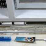
Overview9173During the time between seeing the dirty coils and having “before” data so I could actually clean them, I ran across a long skinny brush that looked like it would be useful.  It wasn’t.  Since the fridge is kind of compact (~24″ deep so it doesn’t stick out past the counter top), the coils are really crammed into a small space.  Lying with my head on the floor was the only way to work on it, and there was only about 1/4″ between the 2 layers of coils.

LeftCoilBeforeAfter9167RightCoilBeforeAfter9169I ended up making a couple of swabs from rags and 0.80″ galvanized wire to dislodge dust deeper in the coils.  With those and the help of a shop vac, the coils came out a lot better than they started.  I cleaned off the front grate and put it all back together.

DoneWithToolsUsed9187Now all I needed was the “after” data.  By this time I’d learned the drill of running the clear-EEPROM sketch, loading the data logger sketch, and clamping the Arduino so I could see the LED over the top of the fridge doors.  I’d also learned to not touch the batteries to check their voltage thus risking a momentary power glitch that would restart the data logger to the beginning of EEPROM, overwriting the day-and-a-half worth of data collected so far.  The “after” data collection went well.

Data presentation

I didn’t know how to look at the data, so after the first logging I started to play.  Output from the EEPROM dumper was .csv for easy import to a spreadsheet to make graphs.  First try was a count of contiguous “on” samples.  Not very helpful, so I added a column with the count of “off” cycles between run times.  A little better, but I finally realized what I was interested in was the duty cycle.  After a few false starts, I settled on total “on” counts divided by total samples over a two hour bucket time.  It was very convenient that the data just stayed safely in EEPROM over the many iterations of the data dumper.

The graph was still pretty noisy – extra long runs after opening the door, ice maker cycles, etc, but over the ~52 hours of data collection there were a couple of periods from which I could infer a “typical” duty cycle.  Running the same bucket params on the “after” data, I got the two-line graph I was looking for.

I put eyeballed “typical” lines in for both runs, trying to be as honest as I could with each.  The difference wasn’t nearly as great as I’d hoped – only a few percent – but it isn’t too hard to convince myself there’s a measurable improvement.  And now I have my data, the writeup is done – and the coils are clean!  Of course I still have to try to get a video of the coil winding (probably at W88), write that and the electronics up for these project notes and maybe do an instructable, make a more permanent data logger – maybe a separate PCB with 128 or 256KB of EEPROM, some calibrated op-amp inputs for analog in, a dedicated 328P running a lot slower than 16MHz to keep current draw down, a nice barrier strip with a couple of digital and a couple of analog inputs and code to make it sleep most of the time – and write that up.  Fortunately, I don’t have to go to work tomorrow.  🙂

Update 2/12/13: I tried out the coil winding technique at W88.  There’s a little blog post on it here.

Update 10/6/16: Not quite the place for this, but it’s the only fridge post…  Water dripping into the basement turned out to be from the broken, hardened bottom end of the 1/4″ plastic pipe going up the back of the fridge for the icemaker.  I cut 1/2″ off and put it back in the compression fitting, and it seems OK, though there’s no slack at all any more.

I’d fought with a much worse leak in the plastic supply hose years ago, and (possibly after the second time?) replaced it with 1/4″ copper so I wouldn’t have to go thru that again.  Since this leak only happens when the icemaker cycles, I’ll probably stay with plastic here, though I’m now quite motivated to put a water sensor/alarm under the back corner of the fridge.

Making this comment a little better fit here, all the dust behind the fridge reminded me I hadn’t cleaned the coils in 4 years.  I looked, and sure enough, they’re gross again.  Thanks to notes here providing clues how best to do it, I plan to clean them soon.

Posted in Home Repair | 2 Comments