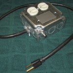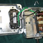
 This sensor has been part of the home automation system for several years. It’s mounted to the wall, and the main AC sump pump is plugged into it. It senses current to the pump, converting it to a logic level a PIC node can read. Connection to the PIC is via the RCA jack on the side of the box.
The main component is a toroid with many turns of red and green magnet wire. I hooked the red and green windings in series to get more output. It might be an 88 mH choke from some telephone equipment, but I have no confidence that’s true. I ran a couple of turns of the wire from the plug to the outlet through the toroid.
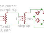
 I didn’t get enough output even with the several amps the sump pump draws to get a good logic level, so I crudely ran the output of the toroid through a little 12VAC power transformer – backwards – to step it up. That did give me enough to run a (silicon) bridge rectifier and get something an input bit on a PIC node could read. Since the PIC reads the level several times/second, there’s a resistor to drain the cap down to get more accurate timing info on how long the pump actually runs each time. For the next current sensor I build, I’ll certainly use Shottky diodes, and probably a little amplifier to sense much lower voltages. And I wouldn’t run something like this into an input bit without a zener to ensure not exceeding the bit’s max input voltage.
The accurate run timing turns out not to be very valuable information. The cycle rate provides about all the info I need.
Sourcing the current sensors – perhaps more accurately current transformers – for such uses is a problem. Real current transformers are $10 or more on Ebay. That’s not a deal-breaker for an important project, but I wanted a cheaper alternative. I have an idea about how to wind many-turn toroidal coils for this application that I’d really like to explore. If it’s successful, I hope it will become an Instructable, or maybe a little article in Make.
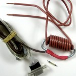
 Update 8/9/11: In another attempt to monitor a sump pump, I tried to get a dry contact closure with a reed switch. It had about 20 turns of #14 wire around a C-shaped steel rod, with the reed switch completing the magnetic circuit. (There’s a similar switch posing next to the heat-shrink that hides the real one.)
Using 2 handshake lines on an RS-232 port on an old laptop, some perl sensed the contact closures. The reed switch was fast enough to bounce a lot – probably at 120 Hz – but a little perl can work around most anything.
It logged enough time-stamped data to show that the ejector pump I thought I heard more than expected really was cycling regularly and way too often. Fixing the leaky toilet made a huge (and quantifiable) difference!

I was going to get some of these to try that next time I order something from All Electronics. 3 for a buck. A better step up transformer would be a speaker transformer 4 ohm primary and hi Z secondary. Maybe better to directly hook Toroid across the differential inputs of an op amp.
Your toroid looks too small to be a Telco load coil. 88 Mh is quite a lot of wire. I once saw the machines that wound them at the WeCo Hawthorne Works. Used a “C” shaped shuttle that rotated through the toroid hole. First set of rotations wound the wire on the shuttle, then a second set in opposite direction wound the wire on the core. All automated – amazing.
FYI, some Telco crossbar switches used this technique to record the number of a phone going off hook. There was a frame with five rows of 10 coils, one side of the line was threaded through a coil corresponding to that digit which made a half turn primary transformer that would fire a thyratron. The coils were rectangular about 3 inches by 8 inches to accommodate a lot of subscriber wires. I have one somewhere.
For sure if we could find parts that worked acceptably for under a buck it wouldn’t be worth trying to wind our own.
Ideal is something self contained that just puts out a logic level (or a dry contact closure), but since it’s going to be within inches of some processor, getting 5V over to it isn’t a big deal. Maybe a dual op-amp with one for some gain (differential as you suggest would be fine) and the other as a precision rectifier. If we could get it to go rail-rail on 5V, we’ve got a fine logic level that’s guaranteed to not hurt input bits.
Another approach that worked marginally was bending a C-shaped ring maybe 2″ diameter out of 1/8″ mild steel rod and fitting a small glass reed switch between the ends. This is a magnetically sound design. I hand wound maybe 20 turns of #14 THHN around it and put it in series with another sump pump. It sort of worked, but the contacts bounced (presumably at 120 Hz). I was using an RS232 port to read it, with a pullup to a handshake line forced high, reading another handshake line – in perl. Got the job done, but it was pretty ugly.
I’ll be interested to hear how you make out with your RF chokes.
I have thought about using surplus toroids too. The op amp idea seems like a good way to go.
I am very interested in your perl code as I am wanting to log a contact closure and thought of using the serial handshake lines but haven’t found much in the way of code examples. Any chance you would post it?
Hi (yet another) Jim,
I’ll try to post something about the original project soon. It was about using the normally open push button on a square dance caller’s microphone (which lifts the tone arm on some Hilton turntables and resets it to the beginning of the record) to do much the same thing – pausing or resetting playing of an MP3 file – for callers no longer using records. It comes down to using handshake lines on a serial port to get a logical input to a program on a laptop. My contact closure sensor for the sump pump was just a hack based on that.
But just in case it helps you get started quicker, I’ve posted the code I used to log the sump here. Looks like most all the old code that injected keystrokes into the MP3 player is still in there.
Good luck!
I ran across http://www.ibuildit.ca/other%20projects/automatic-switch-1.html yesterday. He connects a reverse connected filament transformer across a shorted diode bridge rectifier. I haven’t seen this before, It would put two forward biased diode voltage drops across the 6 volt winding of the transformer, maybe 30 volts out the 110 side. I think the voltage would be independant of current drawn. If that wasn’t enough you could use a pair of shorted bridges and get about 3 volts there.