
While looking at dirty filter pictures for a future project to put a larger air filter in my furnace, I stumbled across an article about cleaning the main condenser coil under a refrigerator. The before picture of the coil with the dust of the ages was gross; the after picture looked much more conducive to good air flow.
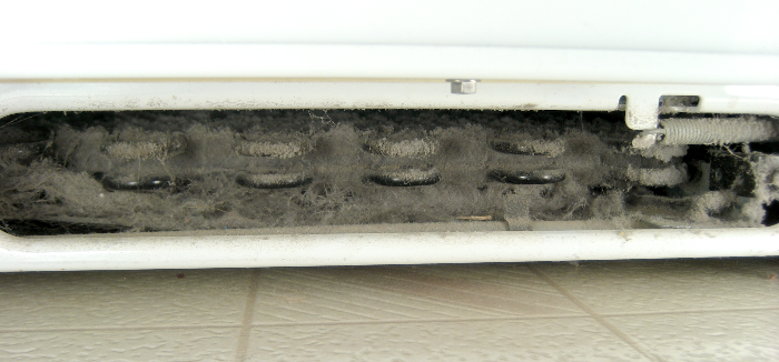 Gee, I’ve never cleaned the coil in our 14 year old fridge. I wonder how dirty it is? <checks under fridge> Eww, gross. OK, guess I better clean it.
But the article had more: There was a nice 2-line graph of electricity used before/after the cleaning, showing significantly reduced consumption after cleaning. That’s cool – I bet I could do that, too! Thus began the yak shaving.
Current sensor
Of course I couldn’t clean the coil until I had “before” power usage data. To get that I needed a way to measure, or at least sense, the input current. I have an amprobe clamp on current meter, but instantaneous reading isn’t really what I need. I guessed what I’d see was shorter run times with the soon-to-be-more-efficient chiller. So an on/off sensor I could log data from would be good.
One way to build an AC current sensor starts with a toroidal core with a winding (which will be the secondary) of many turns of fine wire. Then the (typically thick) wire carrying the current to be sensed/measured is threaded thru the toroid, forming a one-turn primary. For typical household devices, that wire might be 12 or 14 gauge. If there’s room to wind a few more turns of the primary wire thru the core, the output is multiplied by the number of turns.
Unfortunately, I didn’t have such a device. Fortunately, I had a bunch of appropriate ferrite cores. Unfortunately, winding hundreds of turns of wire thru a toroid is a big hassle (though the machines that do it are really cool). Fortunately, I had some ideas about how to wind a toroid mechanically (for some uses) without that magic spinning shuttle thing. I’d never tried it, but this seemed like a good time to start. And it worked 🙂
Unfortunately, the 200 turns I wound didn’t provide enough output to provide a reliable logic level I could log. But since the coil would have to be fairly directly connected to some kind of processor, getting 5V to power some electronics to amplify the signal was easy. A low power op amp, a couple of resistors, caps, and diodes later, I had something that would give a good logic level with a single turn primary carrying half an amp (a 60W light bulb).
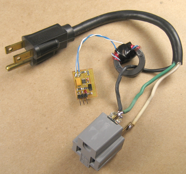 Here’s the coil, electronics, and some crude wiring. A bunch of electrical tape later, I had a device I could plug into the outlet behind the fridge, plug the fridge into, and had a couple of feet of 3 conductor wire coming out to go to the logging device. There are more details here.
Data logger
An Arduino was the obvious logging device, but I didn’t want to leave a laptop sitting in the middle of the kitchen for a couple of days, so I needed a standalone device.
Storage: I have some 64K byte serial EEPROMs, but would have had to make up a board to use them. Hmm – the 328P has 1 KB EEPROM – would that be enough? At say 2 samples/min and running for 2 days, that’s ~6000 samples. I’ve only got 1024 bytes. BUT – since the samples are binary – fridge on or off – I only need one bit per sample. And I have 8192 bits. Code’s a little uglier, but I can handle that.
Power: An Arduino draws ~25 mA at 16MHz. Two days would be ~1200 mA-hr. Brand new NiMH AAs are ~2000 mA-hr, but the ones I have lying around are probably only around 1200. Too close for comfort. (And I’m too cheap to use alkalines if I can help it.)
Are there sleep modes? <researches> Yes! And they only draw a couple of μA. There’d still be bursts of activity, including a short LED blink, but with most of the time spent asleep, it should be OK on 4 used NiMH AAs. A little more studying about sleep modes and how to wake up with a watchdog timer instead of an interrupt, and I was all set. Well, after I also wrote code to dump EEPROM written bitwise, and figured out I’d have to clear the EEPROM with a separate sketch rather than in setup() of the logger sketch. (If I didn’t do that I’d risk losing data before I could get the dumper running after the data was collected: The logger code would still be in flash and would start up – clearing EEPROM! – before I could get the dumper compiled and downloaded.)
 The Arduino lived on top of the fridge held up by a clamp so I could see the LED blink that showed another sample had been taken (every 24 sec). It worked. 🙂 The Arduino code for logging, clearing EEPROM, and dumping EEPROM is here.
And now back to the main program
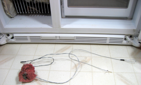
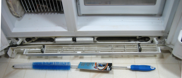 During the time between seeing the dirty coils and having “before” data so I could actually clean them, I ran across a long skinny brush that looked like it would be useful. It wasn’t. Since the fridge is kind of compact (~24″ deep so it doesn’t stick out past the counter top), the coils are really crammed into a small space. Lying with my head on the floor was the only way to work on it, and there was only about 1/4″ between the 2 layers of coils.
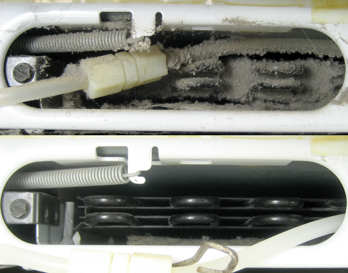
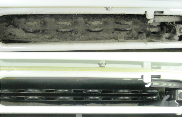 I ended up making a couple of swabs from rags and 0.80″ galvanized wire to dislodge dust deeper in the coils. With those and the help of a shop vac, the coils came out a lot better than they started. I cleaned off the front grate and put it all back together.
 Now all I needed was the “after” data. By this time I’d learned the drill of running the clear-EEPROM sketch, loading the data logger sketch, and clamping the Arduino so I could see the LED over the top of the fridge doors. I’d also learned to not touch the batteries to check their voltage thus risking a momentary power glitch that would restart the data logger to the beginning of EEPROM, overwriting the day-and-a-half worth of data collected so far. The “after” data collection went well.
Data presentation
I didn’t know how to look at the data, so after the first logging I started to play. Output from the EEPROM dumper was .csv for easy import to a spreadsheet to make graphs. First try was a count of contiguous “on” samples. Not very helpful, so I added a column with the count of “off” cycles between run times. A little better, but I finally realized what I was interested in was the duty cycle. After a few false starts, I settled on total “on” counts divided by total samples over a two hour bucket time. It was very convenient that the data just stayed safely in EEPROM over the many iterations of the data dumper.
The graph was still pretty noisy – extra long runs after opening the door, ice maker cycles, etc, but over the ~52 hours of data collection there were a couple of periods from which I could infer a “typical” duty cycle. Running the same bucket params on the “after” data, I got the two-line graph I was looking for.
 I put eyeballed “typical” lines in for both runs, trying to be as honest as I could with each. The difference wasn’t nearly as great as I’d hoped – only a few percent – but it isn’t too hard to convince myself there’s a measurable improvement. And now I have my data, the writeup is done – and the coils are clean! Of course I still have to try to get a video of the coil winding (probably at W88), write that and the electronics up for these project notes and maybe do an instructable, make a more permanent data logger – maybe a separate PCB with 128 or 256KB of EEPROM, some calibrated op-amp inputs for analog in, a dedicated 328P running a lot slower than 16MHz to keep current draw down, a nice barrier strip with a couple of digital and a couple of analog inputs and code to make it sleep most of the time – and write that up. Fortunately, I don’t have to go to work tomorrow. 🙂
Update 2/12/13: I tried out the coil winding technique at W88. There’s a little blog post on it here.
Update 10/6/16: Not quite the place for this, but it’s the only fridge post… Water dripping into the basement turned out to be from the broken, hardened bottom end of the 1/4″ plastic pipe going up the back of the fridge for the icemaker. I cut 1/2″ off and put it back in the compression fitting, and it seems OK, though there’s no slack at all any more.
I’d fought with a much worse leak in the plastic supply hose years ago, and (possibly after the second time?) replaced it with 1/4″ copper so I wouldn’t have to go thru that again. Since this leak only happens when the icemaker cycles, I’ll probably stay with plastic here, though I’m now quite motivated to put a water sensor/alarm under the back corner of the fridge.
Making this comment a little better fit here, all the dust behind the fridge reminded me I hadn’t cleaned the coils in 4 years. I looked, and sure enough, they’re gross again. Thanks to notes here providing clues how best to do it, I plan to clean them soon.
Pingback: How to Clean Your Refrigerators Condenser Coils Or Fan - Green Living Ideas
Pingback: Maximize the use of your fridge. Mom shares 12 nifty hacks to organize and maintain your fridge