“Emergency” watering while we’re out of town

Lauren is considerably more comfortable when we turn the water off when we’re out of town – especially longer trips like our upcoming week at Kirkwood.  Watering – including the very nice impatiens by the  garage – via the normal system is not workable with the water off, at least until the Water Cop valve is in place, controllable and tested.  We’re not there for 2018.  But I really like the impatiens, and they’re not likely to survive a week with no water.

One possibility we considered is water absorbing gels/crystals.  AquaSmart claims 8x by weight water retention.  4 lbs is $25, but hard to get in time.  That much would hold 30 lbs of water – around 4 gallons.  A small help, but only the first few days.  Not great.

Another possibility is using an old fountain pump I have around and some kind of soaker or drip hose in the flower bed.  A big container of water in the garage might supply the system.  Let’s see if that will work.

The Design

Water flow

How much water do I need to put down?  A quick test showed the current hose outside with a breaker nozzle delivers a gallon in ~7 sec, or 8.5GPM.  A nice day’s watering takes about 29 sec with that hose/nozzle.  That means I’d like to put around 4 gallons out per day.  For the ~5 days we’ll be gone, that’s 20 gallons – quite a doable garbage can full.

I tried the soaker hose that usually supplies that bed, but with the low pressure I could get it didn’t work well.

I have a bunch of drip watering stuff, and it’s easy to assemble.  Would that work?

Since it wouldn’t be running house water pressure, the 4 GPH rating of the drippers I had was suspect.  After various tests, it looked like it would work.  Too slow isn’t really a problem – it can run it as long as it needs to, as long as I know the flow rate.

A 20 gal garbage can with the pump filling say a 2 liter bottle that feeds the drippers and overflows back into the can for 8 minutes a day might just work.

Pulled the old Saylor drip irrigation line out completely, scored lots of blue (2 GPH) and maybe 1 aqua (4 GPH), drippers, plus lots of hose.  Laid out and cut off a chunk just right for the flower bed.

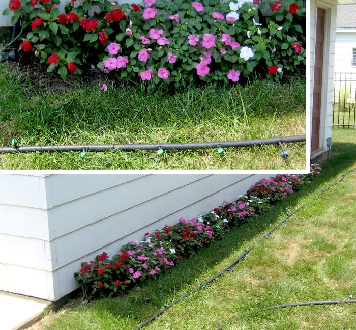
I had about 23 4 GPH drippers, and the hose segment for the flower bed was 192″.  Laid out and punched in all the drippers at a little under 9″ apart.  A little farther apart than I’d like, but should work.  Test time.

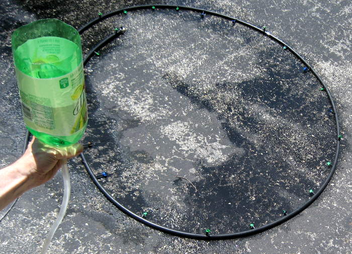
A 2 liter pop bottle ‘tank’ at maybe 36″ head drained in about a minute.  That’s about half a gallon/minute, about as expected.  Seems workable.


Control

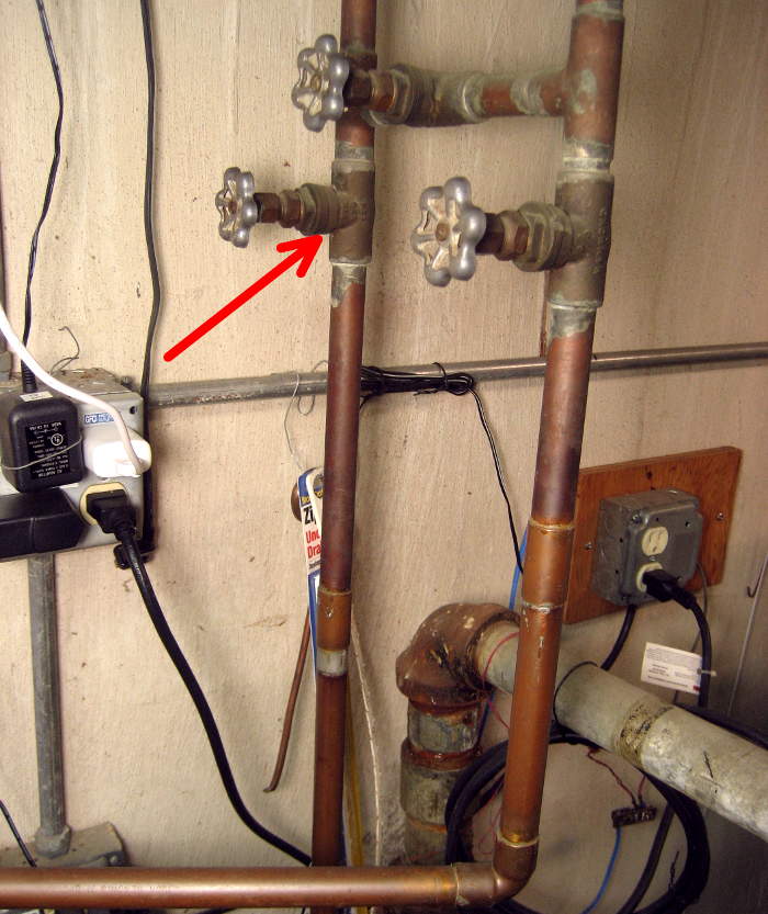
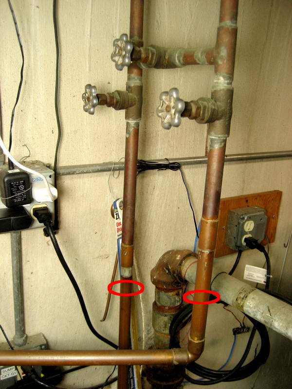
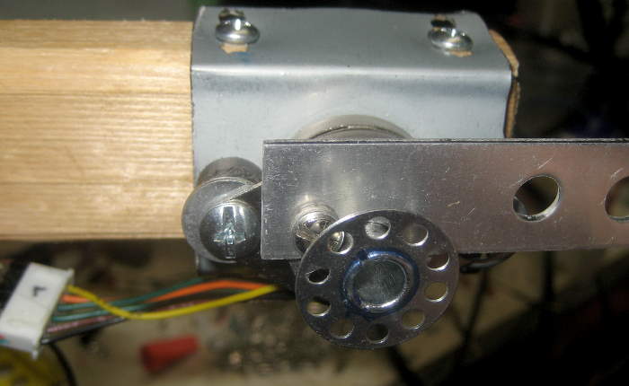
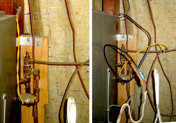
One option to control the pump would be a timer.  But there’s already a valve in the garage that controls water to the window box and a pot, run by 24VAC from a node on the main home automation system.  Since that isn’t useful with the water turned off, I should be able to use that line to control the (120VAC) pump.

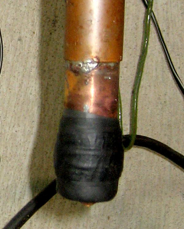
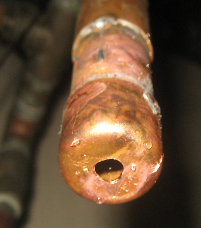
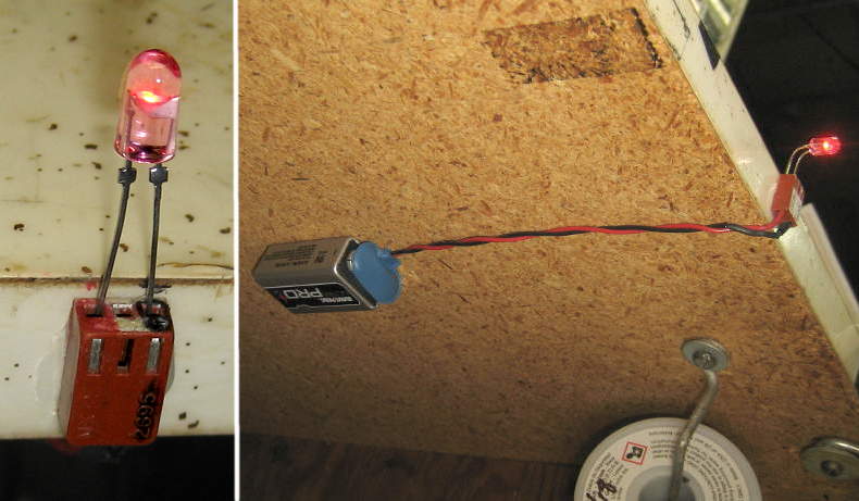
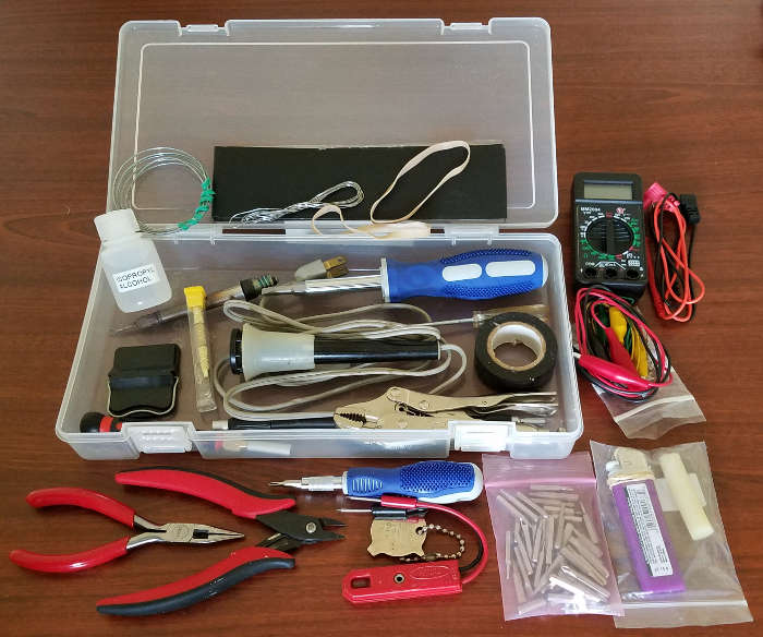
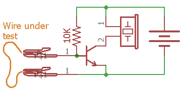
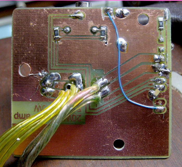
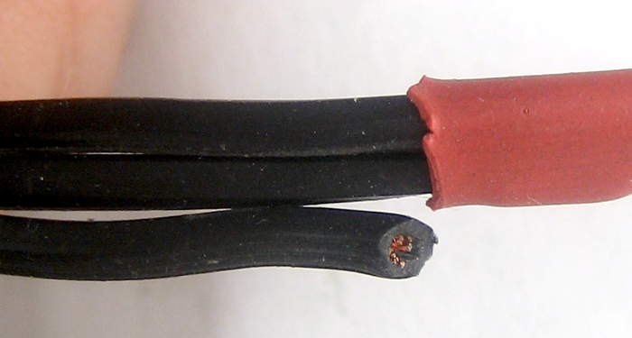
I have an SSR wired up to an extension cord that should easily handle the pump.  All I need is low voltage DC to run the SSR’s LED input.  I should be able to get that from 24VAC with a minimalist power supply.  But how much current does it need to provide?

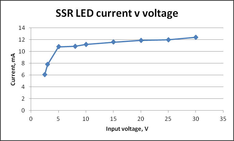
I figured the SSR input – marked 3-32VDC – would be an IR LED and a resistor, but some quick  measurements proved otherwise:  Something in there is implementing a more or less constant current load of ~12mA.  OK – that just means I need to compute the filter cap value in my half-wave supply for constant current rather than a resistive load.

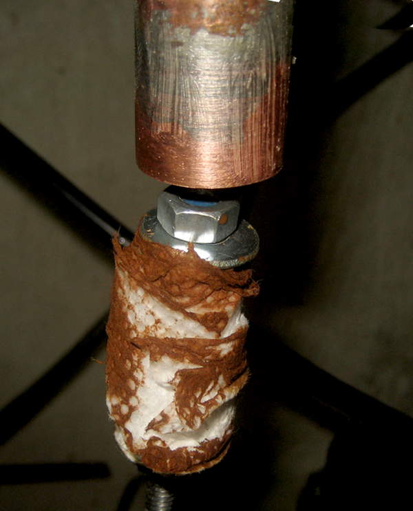
Since the 24VAC sprinkler control transformer puts out more like 30V with no load, the supply will peak around 42V, which is out of spec for the SSR.  At 12mA, a 1K series resistor should drop about 12V, leaving the peak in spec at ~30V.  It increases the power supply parts count by 33%, but Oh Well.

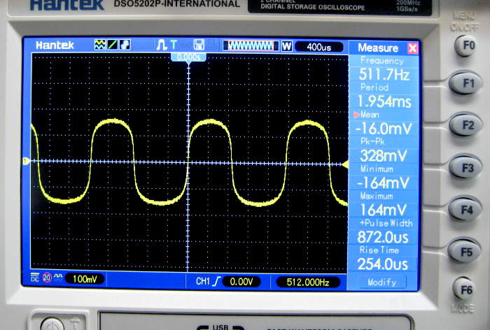
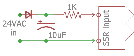
Since the SSR is guaranteed to conduct down to 3VDC control input, I could 
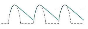
afford a lot of ripple (to keep the filter cap small).  Sorry for no 
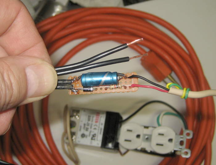
scope pic, but the observed voltage across the SSR input looked about like this, with the peak at 29V and the bottom of the ripple at 4V.  Arguably ugly, but completely in spec.  Here’s the implementation.

First Test

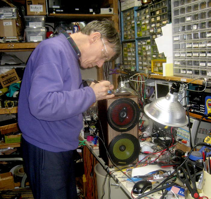
Got it all hooked up for first try (with several days yet before we left!).  Instead of hooking up the SSR control supply to the wiring for the garage valve, I brought a 24V transformer 
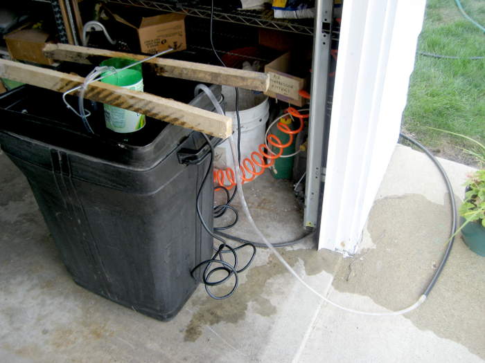
out and plugged it into the conveniently switched outlet for the air compressor (and unplugged the compressor).  I turned the pump on and off so many times during testing that that wall switch was way more valuable than I ever dreamed when I first hooked up to it.

But the system failed 3 different ways during the first few tests:

  • The pump frequently only started when manually shaken/twisted.  That’s fatal.
  • When the pump did run, sometimes it could barely lift water into the tank.  And I wanted the tank a foot higher!
  • The line to the drippers never fully filled.  The tank was in the garbage can, and the output had to go uphill to get out.  It did, but lots of air remained in the line.

Three different failures for a system that needs to run unattended is pretty much a guarantee of ultimate failure.  Bummer.

Shut Up and Change the Plan

An interesting point of view change slowly took place.  I grudgingly looked at fountain pumps at Home Depot.  There were lots to choose from, up to ones claiming 7′ lift.  While this wasn’t formally a junkbox project, I had really planned to use the pump I had.  But that wasn’t a requirement.  If I had to go buy a pump, I guess I could do that.

With that option on the table, I realized (surprisingly slowly) that if I had a suitable new pump, all 3 problems could be solved:

  • Of course a new pump would start every time.
  • If suitably spec’d, I could get whatever lift I needed.
  • With enough lift, I could raise the tank above the garbage can, probably allowing the line to the drippers to fill solid with water, taking full advantage of the head provided by the tank.

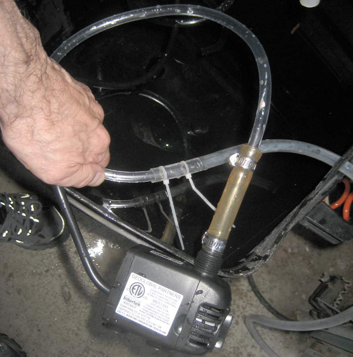
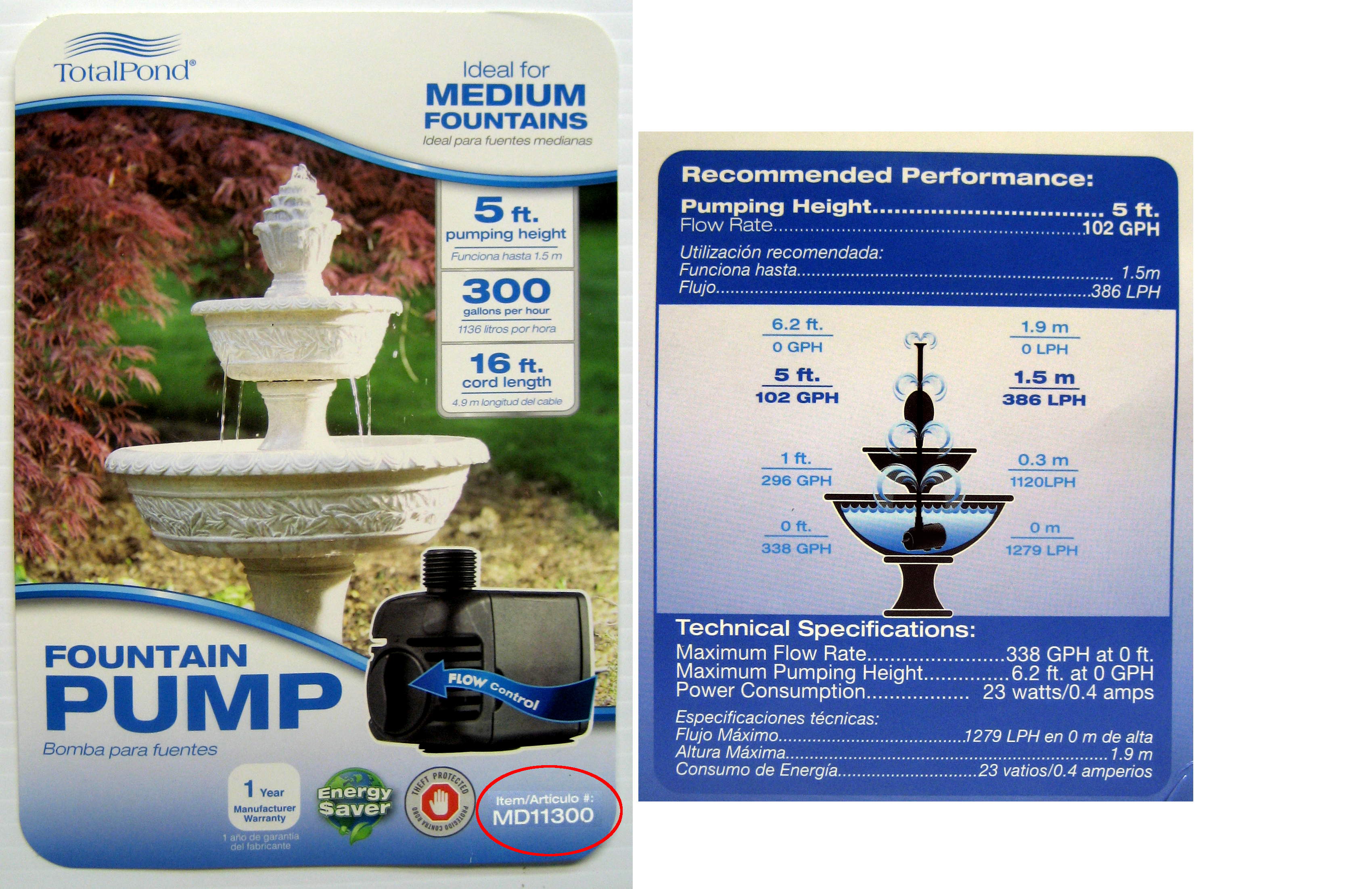
I got the pump (TotalPond MD11300).  Says it’ll do 100 GPH at 5′.  That’s a little under 2 GPM, and the tank/line/drippers deliver ~0.5 GPM.  And the output fitting was the same size as the old pump to boot!  We’re under way.
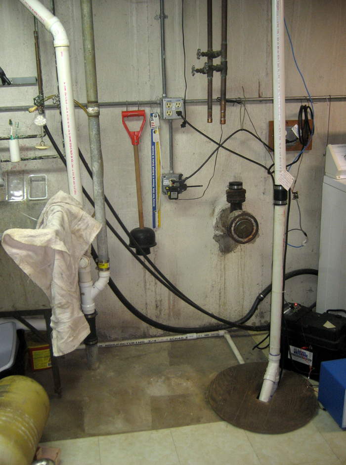
 

System Layout 2

With confidence the pump can get water up there, I hung the tank from the garage door track support, which put it right over the garbage can.  I had to cut a longer piece of the 1/4″ ID vinyl tube to get water up to the tank, but that was fine.  I tied the source tube to the tank hanger with zip ties.  Looks good.

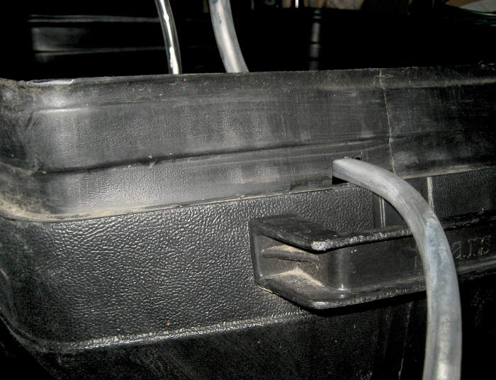
Now that the tank was completely above the garbage can the output line could avoid the down-and-back-up trap that probably contributed to air in the line.  A hole cut in the side of the garbage can should hold the output line nicely, while doing little structural or functional damage.

To gracefully manage the intentional overflow of the tank, I punched a couple of 1/4″ holes near the top of the tank with a paper punch.  Hanging the tank at a slight angle ensures the overflow goes thru those holes.  Here’s the final layout, with overflow in progress.

Well, duh

I ran a few pump-on/fill/pump-off/drain cycles, and everything looked about perfect.  But then it occurred to me:  Why not just connect the pump directly to the output line?  The extra back pressure would just seem to the pump like it had to pump higher, which is completely in spec.  And the whole thing would be simpler and maybe a little more reliable.  I felt a little dumb about the time spent on the tank, but this is better, so let’s do it!

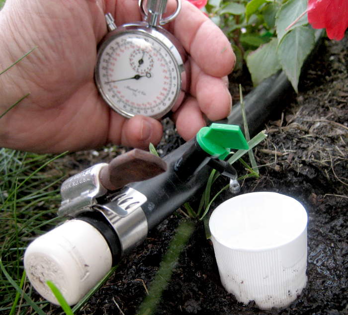
Unfortunately, the new configuration takes away my time-to-drain-the-2-liter-tank flow measurement, and the flow is probably different.  How do I get a flow rate so I can set run time appropriately?  The output of each dripper should be about proportional to the total flow, so before I tore the old setup down, I measured the time to fill a small cup from a convenient dripper:  37 seconds.  That’s with my 2 liter/minute setup.

The water feed tubing fit perfectly inside the output tube.  I replaced the water feed tube with a shorter one, added a couple of zip ties so make sure it wouldn’t separate, and put the pump back in the water.  Then I measured the time to fill that same cup:  32 seconds.  Not a big difference, but decreasing my run time by that 15% should account for it.  Great!

I ran a couple of cycles, admiring the new, simpler setup.  But then I noticed:  With the pump off, there was still water flowing.

Well, damn

The original design considerations came back to me in a flash (splash?):  In addition to providing a constant head, the tank was there to prevent what just I was seeing: a continuous siphon thru the unpowered pump.  The tank designed around that, but then I forgot about it.  So much for my simplifying “improvement”!

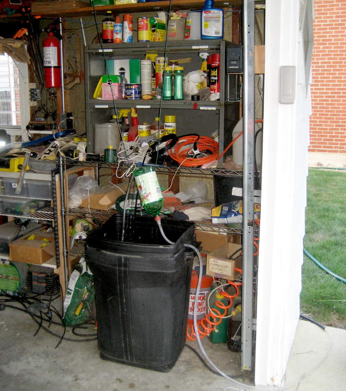
The good news was that I hadn’t quite gotten around to tearing down the suspended tank yet.  So I undid all I’d just done, and went back to the tankful layout. Tested, works.

Automation

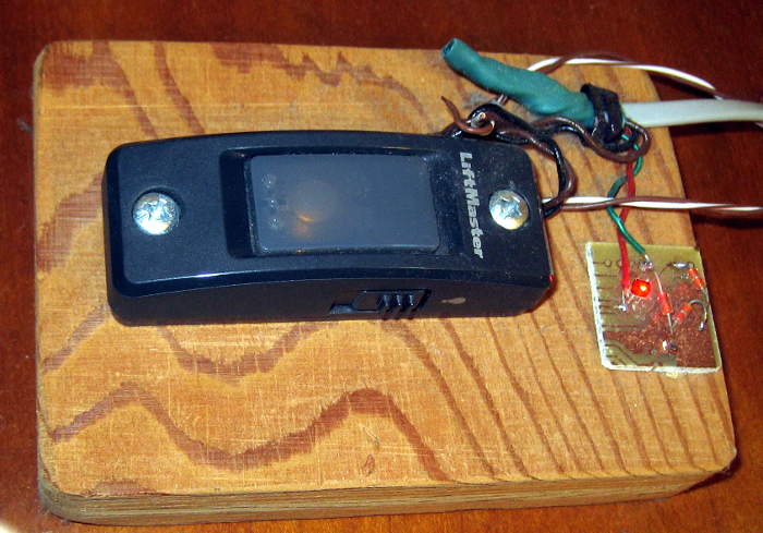
With everything back together and my inappropriate simplifications undone and the embarassment receding into the past, it was ready for the final step: connection to the home automation system.  I disconnected the wire nuts binding the HA-controlled 24VAC from the house to the garage valve, and moved the SSR control power supply from its local 24V transformer to the HA-controlled line.  I logged into the Pogo from a tablet in the garage and told it to turn on the garage valve for 10 seconds.  The SSR LED lit and the pump came on.  Success!

Actually remembered to add a cron job to fire it up every day.  Must measure water depth to see if it works in the morning.

Oops

As I was about to go out later to mark the water depth, I noticed the garage door switch indicator LEDs (in the house) were off – and that’s bad.  They’re supposed to be red when the door is fully closed and green when fully open.  There are switches on the ends of the overhead door track to do that.  (Yeah, the button is ugly.  Lauren has also pointed that out.  Making a pretty version is On The List.)

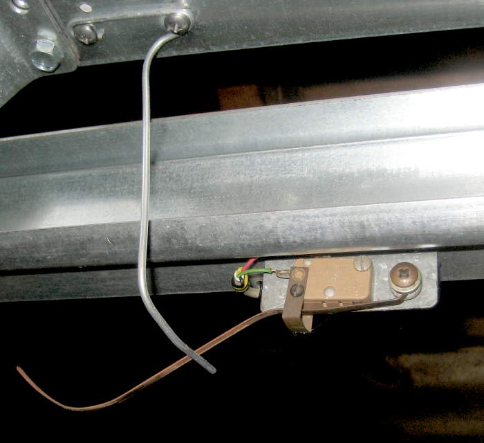
The problem was clear at first glance:  The wire finger 
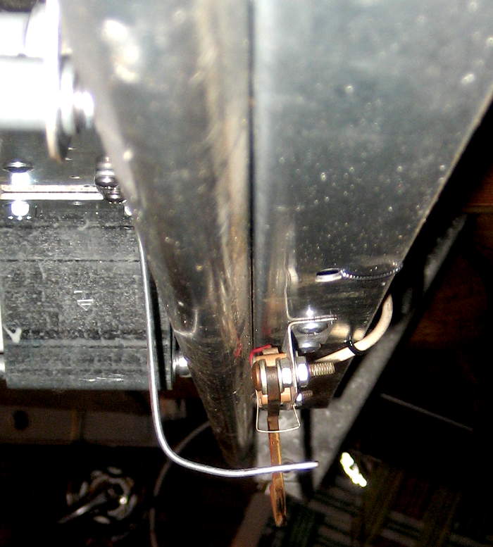
attached to the door that operates the switches passes right thru where the tank support wires hung, and had gotten bent.  Rats.  I think I even saw that coming, but promptly forgot about it.

As a crude but fully functional fix, I bolted little scrap metal brackets into the holes in the garage door track support angle that the tank support wires had gone thru originally.  That let me move the support wires an inch or two, and out of the way of the moving finger.  A quick rebend of the finger and it’s all back in business.

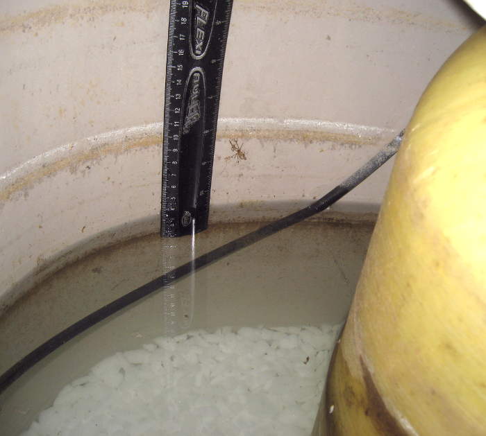
Update next morning: The water level in the garbage can was 3.25″ lower than last night  (and the garage door button LEDs still work).  A rough measurement of the can indicated a cross sectional area of 15 x 18 = 270 in².  At 231 in³/gal, that’s about 1.2 gal/in depth change, indicating about 3.9 gal delivered from the 9 min the Pogo was told to turn the “garage” on for.  The “time to drain” flow calculation of ~0.5 gal/min predicted ~4.5 gal.  Less a little evaporation, sure, but I’d call that a total success!  I’ll post the results after the target trip.

Tuning update same day: I’m generally delighted with the system (and the fact that it was done a couple of days rather than hours or minutes before we had to leave), but that extra time gives me the luxury of a little extra tweaking.

I was pleased to gentrify the overflow path with the punched holes peeing neatly back into the garbage can rather than dribbling water down the outside of the tank, down the output tube, thru the hole in the side of the garbage can and onto the floor.  Yeah, it’s just the concrete garage floor, and the water would drain straight outside, but this is nicer.

Unfortunately, the 3rd hole was too much, and water from it often just dribbled down the outside of the tank.  How should I patch that 3rd hole?

First thought was hot melt smushed into the hole by thumb and forefinger protected by bandages of thin plastic or something.  Might have worked – should try it some time.

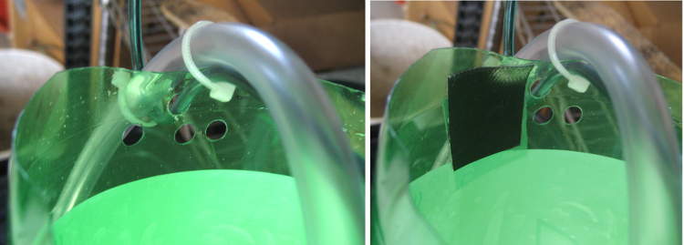
The second idea won as “at least good enough”.  Pieces of the best tape I could think of on both sides, stuck together thru the hole.  I chose Gorilla tape, mostly because I had some.  It only has to last 5 days of being wet for 10 minutes a day.  I’m predicting success; update to follow.

Update 8/6/18: We’ve been back a couple of days now, and the watering system seemed to have worked as designed.  The flowers were fine, and water level in the garbage can was fairly low (but not measured).  It’s run 2 additional days, and the pump is probably sucking air by now.  Guess I should shut off the cron job (or refill the garbage can).  Oh, and the tape covering one of the overflow holes is still firmly in place.  It’s busy out, but I better decide what to do about watering going forward.  Anyway, the system counts as a complete success.

Posted in Home Automation | Tagged , , , | Leave a comment

Water softener leak – and removal

Wet socks told me about the water on the floor around the drain pipe from the kitchen and the laundry tubs, near the water softener.  It took moving a kitty litter bucket full of long scrap, mopping up the water, and toweling the floor dry before I found the leak.  It was coming from a brine tank overflow hose fitting I didn’t know about (or more likely, had long since forgotten about) on our Kenmore Micro Max 625.348460 softener.  Shouldn’t ever be needed, so was never connected.

It produced a juicy drop maybe every 5 seconds.  I put a container under it, and the wet floor symptom was fixed in the short term.

In the only slightly longer term, I plugged the softener transformer back in and ran a recharge cycle.  The water level was noticeably lower after that, as expected.  Interestingly, there were two definite scum rings inside the tank.  After the recharge cycle, water was at the lower one.  The upper one – 10 cm higher – was at the overflow fitting level, and clearly water had been at that level for some time (over the years).

But while I had the tank open to check the water level, I heard a regular drip.  Checked the overflow fitting, and it was dry (and the water level was way below it anyway).  When I put my head back into the tank, I could see ripples in the water with each drop.  Craning my neck a little, I found the source: the upper part of the softener (valves, timer, etc).  OK – maybe it’s slow enough to not overflow before the next recharge.

But now what?

I discussed the drivers and options with Lauren.  The main driver was reducing soap scum in the tub and lime deposits various places (including the humidifier pads).  Less dry skin and maybe nicer hair are additional plusses.  We get lake Michigan water, and while even softer (than lake) water does give the desired results, most people around here don’t bother with softeners.

a) We could join them.  The softener has been out of salt a lot of the time, (or unplugged) so if we just dumped and bypassed it, we’d see little change.  Free is a plus, but not a big concern here.

b) We could get a new softener (and be more faithful keeping it full of salt).  I couldn’t find a drop in replacement, so some copper piping would need to be done to match the new inlet/outlet configuration.  Not a complete show stopper, but I’d much rather have a drop in.  Yeah, I could contribute to the economy and hire a plumber to do it, but that’s a little embarrassing.

c) I could fix up the existing one.  Whatever the leaky part is should be fixable.  I’m sure its 15 year old resin tank is shot, but Sears Parts Direct doesn’t have the part.  I couldn’t find it in a quick search, either.  So a proper rebuild is probably out.

d) We could pass on a softener and get an electromagnetic descaler.  Those seem to have gone from “Snake oil!” to “Well yeah, they do reduce scale buildup, as they claim (except the ones that incorrectly claim to be a softener), but they don’t soften the water or get rid of the calcium and magnesium.”  So that might help a little, but probably won’t stop the soap scum.

e) We could switch from bar soap to “shower gel” or liquid “body wash”.  Those seem to be detergent based rather than fatty soap based, and so apparently greatly reduce soap scum.  Of course the detergent is said to be less friendly to your skin.

f) Oh yeah – we could squeegee the walls and tub and dry them off with a towel after each shower like some people somehow manage to recommend with a straight face.  Does anybody actually do that?  C’mon – I’m not a slob, but that’s just crazy talk.

Too many choices.  No decision was made. (Surprise!)

The leak

Checking a few hours later, I found the water level a couple of inches higher.  Rats.  I pulled the top off the unit (a couple of plastic spring clips) and could hear drips there, too.  There was a steady drip from the outlet connector.  That connection is a push-in plastic tube with an O-ring, held in with a big nominally finger-friendly black plastic circlip (red arrow).

Water was dripping from the bottom where the black clip went thru the outside housing to engage a slot in the push-in tube.  I used the shutoff and bypass valves conveniently provided, and tried to get the connection apart.  Unfortunately, the black clip broke when I tried to remove it.  The silver/gray part (green) threads onto the plastic push-in pipe, pulling a raised collar on a special copper stub up against an O-ring.  I took that apart first, but was dismayed at how much water was coming out of the “turned off” copper pipe.  I put my thumb over the end, and water very promptly sprayed out.  The valve on that outlet pipe (arrow) doesn’t seal well, even after being tightened with a pliers on the hand wheel.  Boo.  Fortunately, I’d put a big bucket under there.

The obvious thing to do was replace the O-ring on the push-in tube.  Sears didn’t have the 0900535 part, but did have a sub STD302213 pack of 5 for 5 bucks.  Fine – but nobody within 50 miles has it.  I found them (pack of 50?) at McMaster Carr, and I was just about to put an order in there anyway, so that would work.  But before I pulled the trigger on that, I thought I should at least look at the old one.

With the copper pipe disconnected, the rest of the black clip came out easily, and the push-in pipe also pulled out easily.  Its O-ring looked fine (though that doesn’t mean much) so I decided to give it a chance.  I wiped down that pipe and the housing it fit into, smeared them all generously with waterproof silicone grease and put it all back together.  If anything, the original leak was worse.

The fix

I manhandled the softener unit to alter the alignment of that push-in tube, and with the whole thing leaning back, the drip stopped!  I leaned it back and forced a piece of 1×2 under the front edge.  No drip!  I cleaned and dried out under where the drip was, and a couple of hours later it was still dry.  Success!  Well, OK – kind of half-assed, redneck success, but it will buy us some time to decide what we want to do long term.  During which time I can walk in that part of the basement without any wet sock surprises.

Soap scum update

11/19/19:  Not relevant to the leak, but since I mentioned it in the driver analysis, here’s a comment on body wash vs soap.  We switched from the white Dial bar soap we’d used for years (OK, decades) to some liquid body wash, and I’m delighted and amazed at the difference it made.  It’s maybe a little less convenient, but also less messy for no soap dish.  But the near absence of soap scum in the tub was the real win.  Yay!

Water softener removal

12/21/19:  Another leak yesterday – in combination with the scum relief from switching to body wash! – made the decision easy to finally get rid of the softener.  The bypass valves allowed me to manage the leak by essentially removing the softener from the water path.  But the valves still leaked, and I was somehow going to have to seal the pipes if I wanted to remove the softener.  On the bright side, Laur reported moderately improved water flow after I opened the bypass valve so water didn’t have to filter thru the softener.

“Managing the leak” also included using a fountain pump (from the “Emergency Watering” story) to pump out the tank into the laundry sink.  Worked well.

How to seal it off?

Of course the main question is how to seal the pipes off.

First plan was 1″ pipe plugs in the galvanized fitting between the copper and plastic of the softener. That was before I realized it was a union. I suppose there might have been a way to modify the plug to seal against the rubber ring, but that made it a lot less attractive.

Then I considered trying to hack the plastic pipe parts, hoping they had a standard cross section and I could find a cap to glue on. Wasn’t sure if they were ABS or PVC. Didn’t even get as far as checking if the same glue worked. That would of course have left even more ugly pipe hanging around.

The right solution

I finally had to admit that the right way was to cut the copper pipes below the valves and cap them. It would get rid of a bunch of ugly and useless piping. (Though a bunch would remain.) And c’mon, it’s just sweating a couple of 3/4″ caps on! Unfortunately, this project only reinforced my embarrassing reluctance to do copper plumbing.

When I pulled the connections off the softener, it became clear how poorly those shutoffs sealed. There was no way I could solder with that water coming out. And I couldn’t have glued anything on those plastic pipes even if I could have found caps and glue.

Solder time

I’d set up as well as I could to do the soldering. I had abrasive cloth band for cleaning the pipe, as well as a wire brush M + F cleaner. I had fresh name brand “self tinning” flux, propane torch (with MAPP as backup) and of course two new 3/4″ caps.

I shut off water with the Water Cop, and opened the laundry faucet, but it kept coming out. Yeah the pressure tank, but this just kept going. Shut off the less old manual valve – kept going. Opened upstairs sink valve. Eventually it slowed to a trickle. I think by that time I’d cut the pipes off. The front one didn’t drip at all; the back dripped a lot.  (I suspect the incomplete shutoff by the Water Cop is directly due to internal cam timing changes I made.  I’ll include that in the Water Cop writeup.)

I started on the front one. Did all the steps. Noticed flux and even solder seemed to spurt out of the joint. Let it cool naturally and moved on to the back one.

Opened the back valve, got lots of water. Eventually that slowed and nearly stopped. I cleaned the pipe and cap and fluxed them both. I ran a paper towel on a stick up to mop up as much water from inside the pipe as I could. Soldered the cap on without apparent problem.

When I turned the water back on, the back cap stayed dry, but the front cap leaked actively – a fat drop/second. HD was closed. Called Ed; he sympathized, said it happens.

With nothing to lose, tried self sealing rubber tape. Complete fail. If I had to try that again, I’d stretch good solid layers on above and below, then several layers (for pressure) over the leaky place. But I’d still not have a lot of hope.

With fat drops falling 4′ into a pan, there was some splashing, so I tied a string to the pipe, squeezed the cut off rubber around it to guide the water to the string, and at least stopped the splash (and noise).

Probable fatal error

The flux and solder spurting out of the front joint were telltale. I’m pretty sure I had the valve 10″ away cranked shut tight. Air (and steam from any water there) pressurized the pipe and blew solder out. Maybe on cooldown sucked it in, too.

Takeaway: Don’t do that. Yeah, I should have been able to figure that out. Hindsight and all. Lots of reading after the fact said any water will cause the joint to leak. But it’s an edge case to seal the end of a short, sealed pipe, so I never came across it in my research.

The next plan

I’ll go get another cap (or 2?) in the morning. I’ll shut off the water again (grumble), and admit it will take longer than I want to drain. I guess I should drill the bottom of the cap to let it drain.

Then I’ll heat it and pull the cap off. I’ll try to wipe as much solder off the pipe as I can, then let it cool. Refit, clean, flux, yada yada. I suppose there’s a chance the cap will try to fall off. I suppose some coat hanger wire pushing it up would be in order.

WITH THE VALVE OPEN I’ll run paper towel up to dry as much as I can – probably twice. Resolder, turn water back on, hope for a seal.

Do it

12/21/19: Got 2 new caps. Drilled the old cap. Usual 1/4″ bit just didn’t work. Looks like I’d reground it. Left it out to regrind again. Boo me. New bit worked fine on the copper (duh). Opened the valve, got lots more water.  Drilling the cap was essential.

After most water out, reheated. Cap came off with no problem, but it showed the problem. Huge areas of no solder. I’m pretty sure some of that was hot air blowing the (flux and) solder out, but some might have been just not using enough solder. Boo me again.

While the pipe was hot, I wiped the soldered end off, hoping the new cap would fit over the solder. It did, arguably even too loosely. I’ll use even more solder given that.

I wrapped some paper towel around some all-thread with washers to make sure it was both pushed in and pulled out successfully and dried the inside of the pipe as best I could. Worked fine.

With the loose cap, it was essential to have a way to hold it on/up. Some coat hanger wire did an admirable job.

The second solder job seems to have worked. Whew.

Getting rid of the carcass

The softener came apart easily – some plastic clips and one plastic screw. The covers, electronics, valve assembly, and even the outside tank were simple junk to the landfill. The big tank even fit in the garbage can without cutting it up.

The problem is the resin tank. In addition to being awkward to handle due to its shape, it weights about 65 lbs. That’s over the limit for several refuse pickup categories. I’d hoped it was largely full of water, but even inverted in the laundry sink, little water came out.

Disposal options:

• Call our waste handler to get a quote for a special pickup. Phone num on Elmhurst web site under refuse. I think that’s the ‘official’ solution. It’s always an option in any case.
• Put a refuse sticker on it and see if the garbage man will take it. This is probably the first thing to try.
• If that fails, stash it away until spring cleanup and see if they take it.
• If that fails, cut the fiberglass tank in half, put in parts garbage over a couple of weeks. This is a messy job with all the resin inside. Saw YouTube of a guy doing it with a chain saw. Or just call the refuse people.

Hmm – hard to believe it’s not full of water. Maybe should start by drilling a hole and see if it drains any. That’s not too messy, it’s nice weather (for Dec) and there’s always duct tape.

Posted in Home Repair | Tagged , , , , , | Leave a comment

Adding audible alert to Panasonic answering machine

We’re pretty pleased with the new Panasonic KX-TGD530 answering machine/wireless phone system.  The 3 handsets (expandable, unlike the AT&T EL52209 it replaced) gives us matching phones for kitchen, bedroom, and computer room.  Matching means only one user interface to learn.

Unfortunately and much to our surprise, unlike the blaring AT&T machine, this one does not provide an audible indication when there’s a new message.  If we get home and don’t happen to notice the small blinking LED, we can go for days (forever) without knowing someone left a message.  I should fix that.  If I can get my hands on the LED leads, I’ll know when there’s a new message, and I can beep or whatever.

I’d already opened the unit up once – to solder in wires for a probably external battery (like I did for the old machine) so it can survive short/medium power outages.  (No battery yet – but the wires are right there.)

Inside is a main PCB connected by 2 heavy ribbon cables to another, single sided PCB that very obviously handles the display and buttons – including the LED that flashes to indicate new message.  Surely those LED leads are brought out on those ribbons, so I should be able to tack my new wires to the exposed ribbon ends, bring that pair outside, and play with them at my leisure.

I couldn’t see the trace side of the display board, but I should be able to light the LED with wires from my edge-of-the-bench LED tester (old dead 9V battery – maybe 6V? – and maybe a 470 ohm resistor) without hurting anything.

Finding the LED leads

Using a continuity tester and then an ohmmeter, I found one ribbon pin connected to power supply minus.  With the negative side of the LED tester on that, I watched the LED and brushed the + end of the tester lead against each other ribbon pin in turn.  Nothing!

Very surprised, I moved to plan B.  Maybe there’s an open collector driver and the LED is connected to +.  I found a pin connected to V+ and tried that way.  More nothing.  Plan C: I’ll take the dumb thing apart and look at the traces.

Murphy arranged for one of the screws securing the display board to be obscured by the main board, so that had to come off first.  Two screws – not bad.  Two more screws for the display board and I could look at what I had.  I tried the LED tester leads directly on the pads of the tiny (0605?) LED – no light.  Very surprising, but consistent with earlier observations.  Using a loupe, continuity tester and ohmmeter, I finally chased the plus and minus leads of the LED (polarity marked on the board – thanks!) to two ribbon pins.  Confident of that wiring, I soldered a pair to those pins, closed it all back up, reconnected the base to power and line, and called and left a message.  The LED blinked, just like always.  So far, so good.

First test:  I hooked my dear old logic tester to the newly brought out LED leads.  There was a faint flash of the Pulse LED, but the logic level showed always Low.  Yeah, I suppose that’s OK – the forward voltage across the LED isn’t really a valid logic High.  But still.

Brief aside on logic testers

I can’t believe they don’t make something like this go-to device – battery powered, no power switch – any more.  There are lots with 2 clip leads – presumably so power and threshold levels match the circuit under test – but for normal TTL or 3V or CMOS signals it’s so nice to just clip to ground and go!  In searching over the years, I’ve found used ones on Ebay branded Sanwa and Soltec – clearly the same device – as well as Vaco.  I don’t think I’ve even been able to find a schematic for making one.  Seems like such a sensible device.  But I guess I’m the only one who thinks that any more. 🙁  Yeah, yeah, I could design one.  But I do still have this last working unit…

First noise

So I made up a simplest-possible proto that should beep on an LED forward voltage and hooked it up to the new LED leads.  It beeped in time with the LED flashes.  When I disconnected it, the LED got a little brighter, but only a little.  Success!

Proof of concept DONE.  Strangely, I feel a little less pressure now to actually do the implementation.  Might just replicate what I did on a bit of perf board (using phone’s power) and stuff it inside.  Downsides are more beeps than necessary, and no way to silence it.  (Except, of course, listening to the messages.)  Or I could put a Tiny85 on the board, listen for flashes, and do whatever more genteel beeps I chose.  One could argue I should at least reconnect the little proto board and battery so if someone leaves a message before I get around to the final implementation, we’ll at least know about it.  Fine.

Can’t stop myself.  Clip leads were too ugly, so soldered 0.025″ pins to the LED leads, and to a 9V clip with an old “dead” 9V for power and wired it up.  And the darn thing started to beep.  WTH?  Then I realized:  There was an actual message on the machine from somebody – and we’d missed it because of the dumb LED-only alert!  Pretty good for its first day/second on the job.

OK – let me listen to the message.  Then I stumbled across a semi-fatal flaw:  The Alert/Play LED remains on as you’re listening to the message.  And so does the new beeper.  In addition to my thinking it was annoying and made it hard to listen to the message, I could project with very high confidence that Lauren would think the same, only much louder.  The attractiveness of putting a processor in the final version just went way up.

But what am I gonna do until then?  I soldered a microswitch to a 7 position 0.1″ header for mechanical support and put its NC contacts in series with the battery.  And I put a label on to remind Laur (and me) to hold it to silence the beeper.  But the layout was awkward with wires on top of the switch, etc.  I ended up with the switch in series with the new LED leads, so at least it was near the front of the breadboard.  Not a great solution, but it should work until I get around to a more proper software-based solution.  Here’s the proto I hope will fly.  Fortunately, we don’t get a lot of messages. 🙂

Update 7/10/18:  The breadboard and microswitch got a fair amount of (mostly but not completely good-natured) flak about being ugly, but by promising that it was only temporary, it was allowed to stay.

We’ve come home to messages/beeping a couple of times since it was installed.  Main goal accomplished!  But the bit about continuous beeping as the message played hit home again.  And its end-of-all-messages cycle takes an annoyingly long time until it finally shuts the LED (and noise) off.  I guess the Tiny85 needs to only beep on flashing input signals.  OK – it’s just code.

Update 8/6/18: To keep from draining the old 9V battery while we were gone for a week at Kirkwood, I unplugged the battery.  Yeah, it wouldn’t be beeping like it was supposed to do when we got home, but surely I’d remember to hook it back up when we returned.  A day or 2 after we got back, I noticed and remembered – and listened to the 2 messages the flashing LED was valiantly, if ineffectually trying to tell us about.  Then I plugged the 9V back in and we’re back to <ugly but alerted>.

First ‘smart’ beeper

9/27/21: Partly inspired by Steve’s comment, I’ve made progress on making the dumb beep stop while you’re standing at the machine playing back a message.  A Tiny85 listens to the LED voltage, and beeps only when the LED is flashing.  That means it might miss the very first (or last?) flash/beep, but that doesn’t matter at all, since its real job is to be beeping when we come home.

It was fortunate that I already had power supply leads coming out (for some future backup battery), so I already had all the connections I needed.  After some voltage measurements and head scratching, I suspect there’s a 3V regulator inside after the 5.5V wall wart.  Here’s what I’m guessing is inside, with my proposed next version.

Since I’m out of the nice little general purpose Tiny85 PCBs from years ago, I made up a Digispark for the job.  But then I worried about drawing too much current from the 3V regulator, so switched to a bare Tiny.

The datalogger showed the LED flashed very consistently 50% duty cycle with 620mS on and off.  For testing, I wrote a simple simulator for that square wave on another Digispark.

I think the 15 lines of code for the actual beep controller worked first try.  But after I set the clock prescaler to /32 to cut current consumption (it ran at ~1.5mA!) I had to tweak the timings considerably more than I expected to get it to work.  I even had to drop back to /16 prescaler (still only 2mA) to get a little more precision on the timings.

But it seems to work as designed.  Yeah, it’s still on a breadboard on wires out the back of the phone.  But there’s no longer a 9V battery, and no microswitch I have to hold down to stop the dumb beeping!

10/4/21: I just had the pleasure of walking up to the beeping machine to play a new recorded message.  As soon as I pressed ‘Play’, the noise stopped – exactly as it should.  The rest of the Play/Erase/whatever interaction continued without noise and without having to balance the stapler on the ‘shut up’ microswitch.  Perfect!  Well, except that it’s still all on a breadboard outside the case.

Posted in Miscellaneous | Tagged , , , , , , , , | 2 Comments

Hacking reading glasses

This is part of the post-cataract adaptation saga.  I had a Technis Symfony toric IOL put in my left eye 4 days ago as the first of 2 cataract surgeries.  While I have concerns, I can certainly see better than without the lens.  This hack is part of exploring my new vision.  (Update:  more hacks at the end of this.)

The first thing I did was to remove the left lens from my “good” $$$ glasses – 8 month old progressives I wear when I’m out of the house, and always when driving.  That gave me something I could drive with and a sort of monovision so I could read labels etc at the store.  Worked pretty well – certainly much better than with the left lens in (or with nothing).  Yeah, looked kinda funny. Oh well.

Then I took a pair of single vision “reading” glasses – maybe +2 or 2.5D from my normal distance prescription – that I use for reading/bench/computer work at maybe 13″ and removed the left lens from those.  That provided a more extreme monovision for around the house that let me read (right eye) and still have some moderate distance vision – with the less-perfect-than-I’d-hoped-for left eye.  I used those at the computer, but got a headache after the first extended session.  I put a loose cardstock patch over the left side of the frame, and that pretty much fixed the headache.  Later, and in shorter sessions, I got away without the patch.  Brain may be getting over saying “WTF!?” and just ignoring the fuzzy eye.

I was a little concerned that I was teaching my brain to ignore the left eye when I used those glasses – which I did a lot.  And since the left eye wasn’t great anyway, that extra training didn’t seem like a good thing.  But in order for the left eye do any work at that distance, it would need a normal reader/magnifier lens.  Off to Walmart.

The donor glasses and measurements

I tried a few readers, and decided +2.0D let the new left eye see about right at 13″.  I chose a $6 pair with largish lenses to give me something to work with.  I popped one lens out (the wrong one, as it turns out) and when I held it over the missing lens of the good old readers, it seemed to do about what I expected.

Of course I’d need to set the PD correctly.  The glasses I’ve gotten from Zenni were ordered with 65mm PD, but since these were for closer work, I expected my eyes to be more converged.  Holding a ruler up to the centers of my eyes and looking into a camera about 13″ away, I took pictures that showed a PD of ~62mm.  Now I have a target.

To find the optical centers of the old and new lenses, I set up a laser diode pointing down at the bench, and marked where the beam hit.  Holding the lens near the laser, I moved it around so the beam hit the same spot on the bench as without the lens, and marked the spot the laser was going thru the lens with a black Sharpie.  As a double check, I moved the lens around and verified that I saw the shadow of the Sharpie mark when the spot was in the undeflected place.  With marks on the right lens of the glasses and the loose +2 lens, I was set for the next step.

Putting the new lens in

In an awkward maneuver requiring more hands than I had, I held the loose lens up to the frame and slid it back and forth so the 2 marked spots were 62mm apart according to the ruler I was holding with my left foot.  With a combination of trying not to let the lens move and a mental snapshot of about where it had been when the PD was set right, I marked the outline of the frame on the lens with a Sharpie in my third hand.  A double check showed the spots still about 62mm apart.  Good.

The lens didn’t completely fill the frame, but looked workable.  So how do I cut the lens down?  One corner just needed to be relieved a mm or so, so I put on safety glasses and took it tentatively to the belt sander.  The acrylic lens sanded away perfectly, and it didn’t feel at all like the lens was about to shatter.  I have no idea why I thought I’d know what that felt like, but I seemed to.  Removing the rest of the lens down to the Sharpie outline (maybe 1/4″ in places) was quick and uneventful.  I started shaping the edges so the front surface of the lens would fit into the concave inside of the frame.  A few cut and try iterations, and it was ready for final fitting with a file.

I rotated the lens a little to let it sit where it wanted in the places not designated for the final fitting.  I think that was a good idea, and probably avoided unpleasant surprises about having removed too much.  Of course since there was no astigmatism to worry about, the exact orientation of the lens didn’t matter.  A couple more iterations with a file, and the lens snapped in, and has been there ever since!

Do they work?

When I put them on, things seemed about in focus for both eyes, but the difference in magnification between the eyes was very evident in “swimming” movement when I’d turn my head.  No surprise, but duly noted.

I could vaguely see the center spots on the lenses, but had trouble matching them up.  Turns out when I was looking straight thru the centers of the lenses, the spots were so closely superimposed that I missed them.  That test passed with surprisingly flying colors.  I cleaned the heavily handled lenses and took a pic showing how the new lens doesn’t fill the frame.  Pretty close, though.

I sat down at the computer to write up these notes (while wearing the new glasses) and the big limitation leaped out:  The only way these are practically useful is when I’m looking right thru the lens centers.  Image fusion suffers a LOT anywhere else.  Interesting.

On the comment about having removed the wrong lens from the OTC readers:  I arbitrarily took the left lens out to fit into the other glasses.  If I’d taken the right lens out, it would have left the option of trying those readers as near-vision monovision, with 13″ for the left eye (new IOL plus the +2 reader lens) and my naked old right eye with its 7″ working distance.  Not a big deal, and fixable for another $6.

Hmmm – just tried it with the new readers upside down.  That worked well enough to let me see how it worked/felt – about as I expected.  Interesting, though not terribly practical.  Done.

It’s not clear whether these will be useful or whether I’ll pop the new lens out and use them one-lensed as they started.  I’ll post an update some time.  But it was an interesting experiment in any event.

Update a few days later:  Yes, they’re useful.  They served well for the week or two until the second lens replacement surgery.  Success.

Astigmatism

Update 7/10/18: (This is written after the fact, and the timings of various bits were intertwined.)  A refraction after the first replacement had shown (to the doctor’s disappointed surprise) that there was about 1.25D of astigmatism in the left eye.  I couldn’t see very well (20/60?) with that eye, and assumed (incorrectly) that it was mostly due to the astigmatism, and so was anxious to correct for it.  I was also in the early stages of struggles with readers.  I ordered a pair of cheap glasses from Zenni  ($15 including priority shipping!) with the needed cylinder in the left eye, and +2.0 sphere in both eyes, assuming correct vision in the right after it got its new lens.  I figured that would give me a good pair of readers, at least for starters.  They were in daily use as soon as they arrived, and have been a big win.

Hack 2: driving glasses

But what about driving?  I ordered a single lens blank – plano, but with 1.25 cylinder to fix the astigmatism.  Errors at the vendor (eyeglasslens.com) delayed the order, but when it finally arrived,  I had 2 things: first, the lens to make some driving glasses; and second, a good way to see how much the astigmatism correction helped (including the angle).

It was a rush job, as we were about to drive to an out of town weekend, so no pics of the 2″ blank. 🙁   I found an old pair of glasses (I have lots!) for a frame donor, and took both lenses out.  Holding the new lens up, I turned it until left-eye vision was clearest (+/- 10° ?) and marked the orientation.  (And of course with the lens rotated  90°, it’s noticeably worse with the lens.)

I sketched the outline of the frame on the lens much as above, and again cut the lens down on the belt sander.  It’s acrylic, and that went pretty fast (leaving a LOT of white swarf on the sander).  A couple of iterations, plus grinding/filing the edges to a pointed cross section to fit in the groove in the frame, and I could put it in.  Not perfect, but fully good enough, and hasn’t fallen out in many wearings.

As a plus, those frames fit some old spring clip-on polarized sunglasses quite well.  I use the glasses every time I drive, and the sunglasses work very well when it’s sunny.  (But see sunglasses update here.)

As for observing how much the astigmatism correction helps, the lens was a good tool.  While I played with it in my hand as soon as I got it (duh!), the best test was after it was mounted in the frame.  In the car, I could look at distant lettering with/without the glasses for an excellent comparison.  The bottom line for this one data point is that the 1.25D of cylinder correction makes not a huge improvement, but a clearly visible one.

(The astigmatism was only a modest part of the poor vision in my left eye.  An irregular swelling (CME) on the macula portion of the retina was mostly responsible.  That responded to a course of drugs (drops) over several weeks, and is all cleared up.)

First crack at interim glasses

6/11/18: This isn’t really a hack, unless you consider writing your own glasses prescriptions a hack.

Readers are a real nuisance.  Half-eyes on the bridge of my nose, readers that live on top of my head until needed, readers in pockets, shirt collars – none worked well all the time.  (And I’m not about to wear them on a chain around my neck.)  Let’s just get some bifocals I can wear all day and see if that works.  Of course we restart late in the year after Foulkes fires up his lasers and fixes what needs fixing.  But I need something stable until then.

The latest refractions from Foulkes (bless his patient portal for making all visit docs available!) showed +0.5D sphere in both eyes, along with the 1.25D cyl in the left eye.  I had some +2.25 (hingeless, rimless) readers, but the old +2 Zennis seemed a little better.  So I ordered new Zennis with +0.5 on top, and a 1.5 add to get back to the 2.0 the old Zennis demonstrated to be about right for near/reading.  And of course the cylinder for the left eye.  Those should make distance a little better, bring all the intermediate in a little, and of course provide readers always at the ready.  (Might need to learn to be careful the add doesn’t cause me to fall down the stairs, tho.)  $55 with priority shipping.  Might get here before Kirkwood.  Will update when they come.

Zenni bifocal update 7/28/18: I’ve had these for just 10 days now, and they’re a great success.  They’ve provided 2 bits of value – one unintentional.

The big win is that by wearing them most all the time, I can always read (phone, papers, whatever) without having to search for readers.  The best I’d come up with before was the frameless, hingeless +2.25 OTC readers that I wore on top of my head most of the time.  I was starting to get used to those lightweights, but they’re not good for outside/breezy or even inside bending over, etc.  At the cost of always wearing glasses, these completely avoid those downsides.

In an interesting tradeoff win and data point, the +0.5 top part is not correct for distance.  I’m noticeably better off with my one-lens “driving” glasses for driving and the like.  That’s fine – the one-eyes live in the car.  But that top part provides better intermediate vision – a definite, if small benefit for the distance to a lot of stuff in the house.  That also makes the jump to the (lined) reader part less jarring.  I suspect that’s a plus, though I’m not certain.

The valuable insight I didn’t expect, however, is what it’s like to live a little nearsighted.  That will be helpful in deciding how to direct Foulkes for my final Lasik.  I’m considering asking for maybe 1.0-1.5D nearsighted.  While that would absolutely mandate glasses for driving, it would make daily interactions easier.  If it could bring my vision in enough to actually read without glasses, the tradeoff that distant things weren’t crisp would probably be worth it.  Of course the Symfonys would still be doing their part in helping that.

Hmm.  I wonder if I should get some more Zenni cheapies in that range to let me live with the vision I’m planning to ask for.  Single vision, maybe +1.25, with the cylinder, of course.  The +2 Zennis are sort of like that, but arguably too strong.  They’re great for reading and computer use (I’m wearing them as I type this).  I guess the interesting and powerful idea is to get some cheap glasses to test out life with candidate vision correction.

First crack at simulating final no-glasses vision

8/6/18:  I ordered some +1.5 (plus the astig correction) single vision throwaway testers from Zenni ($15.54 including expedited shipping!) before Kirkwood and have had them for a few days now.  They’re blue just to be easy to identify.  The goal was to see what it would be like to live with that correction (without glasses) as the result of asking for that from the LASIK.  Very interesting.

I can pretty much read with them, and as expected, the distant world is a little blurry.  The experience is much like my old “computer” single vision glasses.  I could probably live with that around the house (as I did before when I wore those glasses 95% of the time at home).  And while I could no longer see leaves on the trees crisply through the window as I got out of bed (with no glasses) as I do now, I could read my phone.  I’ll make that tradeoff happily.

Yes, I can see “well enough” across the room.  But that mild disconnect from the world being a little blurry is where the questions begin.   I’ve gotten used to seeing pretty well across the room with the bifocals (and still being able to read well).  I wore the new (blue) single visions to the grocery store the other day, and while I could read product labels acceptably, the whole blurry disconnect from everything else made me wish I had my good old bifocals.  That was an interesting surprise.  Of course I could just keep my driving glasses on in cases like that, and look under them to read.

Or have that planned LASIK outcome and just plan to wear glasses all the time:  -1.5 on top, with a 1.5 or a little more add on the bottom.  Progressives have worked well in the past, so those would be likely.  I’d still have the option of no glasses for the computer, and I could still read the phone on the nightstand in bed with no glasses.

I suppose another option (since I’m going to have to wear glasses full-time anyway) would be to keep my about-perfect right eye, and just do LASIK on the left to fix the astigmatism, leaving it correct for distance.  That would save me one LASIK surgery, give me the option of driving without glasses, and let me use OTC readers (or OTC plano/add bifocal readers).  But I couldn’t read my phone without glasses.

Hmm – I suppose as long as I had to do something to the left eye for the astigmatism, maybe have him set that at +1.5 or so, giving me one eye monovision for no-glasses reading.  Hmm.  (Update:  He mentioned possibly using the less-invasive LRI rather than LASIK for the astig correction – which changes things a little.)  I wonder whether that difference would affect binocular vision/ depth perception with my +4 (+2.5OS/+4OD with this monovision) bench close-up glasses.  We had discussed and discarded mono vision early in the consultation phase out of concern for just such discomfort with close-up glasses.  I suppose one possibility would be to do that for the left eye and wait-and-see for the right.

Anyway, this $15 investment has been a total win.  I got the desired data point of whether +1.50 is just right or not.  Another $15 to check out +1.75 might also be worth it.  (I already have the +2.0s.)  The surprise “I want my bifocals back” at the store was illuminating.  I don’t know yet what I’ll end up deciding, but I’ll be able to make a MUCH more informed decision.  Certainly much better than accepting the surgeon’s default recommendation of “Just fix ’em for distance!”.

Update 8/7/18: Small new insight:  If I have him do LASIK to make me 1.5D – heck, or 2.0D! – nearsighted so I can read well in bed, the blurry world disconnect probably isn’t very relevant:  If I expect to wear glasses (bifocal/progressive) full time anyway, the only time the blurry world would occur is in bed or in the shower until I put my glasses on.  (Just like my pre-IOL uncorrected vision, but less extreme.)  Then, whatever nearsightedness I choose for comfortable reading, the tops of my glasses will eliminate the fuzzy world, and the add will bring me back to good reading.  So how nearsighted I choose to be without glasses really has very little other impact.  Interesting.

Update 8/9/18: A minor update on the blue single visions:  I’ve pretty much stopped wearing them.  They gave me the insights I wanted, so I’m back to my good old bifocals.

I pretty much wear my (astig corrected) +2 single vision Zennis at the computer (for no sore neck).  That would be like just taking my glasses off with the proposed +1.5 (or +2.0, toward which I’m increasingly leaning) post-LASIK outcome.  And the bifocals the rest of the time.

I’m mildly considering having another pair of bifocals (or possibly progressives) without the incorrect +0.5D my refractions have consistently reported.  Those could truly be full time glasses, giving me everything from driving to reading, and providing a good taste of what that final arrangement would be like.

On the technical point:  What’s up with my refractions (including the most recent on 8/7/18) all showing I prefer +0.5 for distance?  While driving, it’s completely clear (no pun) that I see more clearly at distance without that +0.5D correction.  When I brought it up with Foulkes, he said it was because my pupils were constricted in daylight and thus didn’t need the correction.  Sorry – doesn’t make sense to me.  Constriction provides more depth of focus, sure – but the basic focus doesn’t change.  And the same difference is seen at night.  Troubling.

Update 8/10/18: Not glasses related, but more of the post IOL story:  Saw Dr George today.  The film he saw last time over the CME was gone, and he’s not concerned about the remaining macular thickening if I’m OK with my vision.  He recommended a laser procedure to create scarring to help reattach the vitreous to the retina (left eye only), possibly avoiding a tear and retinal detachment in later years.  I agreed and he did the procedure on the spot.  Uncomfortable, but presumably very worthwhile.

Update 8/21/18:  A couple of bits of news.  One is that I just ordered some “full time” interim bifocals (Zenni, $55) that should work both providing readers in the house and be good for driving.  It was a toss-up whether I should try out progressives from them (and for me), but went with bifocals for the wider reader area.  I expect the final situation (post +2.0 LASIK) will be full time glasses much like these, and these should help me learn what that will be like.

I went with frameless and hingeless to save a little weight (and since they’ll probably never be in a case!).  The OTS +2.25 hingeless readers I tried to wear on top of my head seemed nice.

The prescription runs into the other news.  It was just like the hinged rimless bifocals I’ve been wearing every day, but +0.25 instead of 0.5 on top and +1.75 instead of 1.50 bottom.  Really close, but I justify them to see what life will be like without the hassle of changing to driving glasses.

What drove that prescription?  Frustrated and annoyed that I couldn’t trust refractions from Foulkes (WTH!?), I wanted a pair of test lenses with + and – 0.25D so I could test and tweak and find correct prescriptions.  Having +0.5s as well as stronger readers, I figured these new lenses would cover what I needed.

I could order from the place I got the 1.25D cyl blank, but at ~$35/ea that was too expensive.  I called Zenni, but was told they couldn’t sell me just the lenses.  Grumpf.  So I ordered a pair of glasses with the cheapest ($6.95) frames with one “eye” at each prescription.  I chose large frames to leave me with the maximum lens size.  With cheapest shipping, they were about $12.  Fine.

The lenses popped out easily, and let me check out both my +0.5-on-top bifocals and my bare eyes.  I’m now quite comfortable that the best distance prescription (until LASIK) for both eyes is sphere +0.25.  I can see better with each naked eye (or the current driving glasses) with the +0.25, and better with each with the bifocals with the -0.25 lens.  Twice great:   Now I have a prescription I’m confident about (and ordered with) for the full-time glasses.   But maybe more importantly, it looks like the refractions from Foulkes are 0.25D – not 0.5D – off.  I can accept that much more easily.  And now I think I can trust refractions from Foulkes by adding my +0.25D correction, and order future glasses based on that with good confidence.

Posted in Vision stuff | Tagged , , , , | 2 Comments

Repair of Keith Rubow RF Remote transmitter

This (~12/11/17) is the fourth repair of this device – I can’t believe I didn’t record the others.  The $75 device is a 6 button “garage door opener” and USB receiver designed to control music playback software for “tape group” square dances.  It works very well, and with its macro capabilities to insert keystrokes into a window’s stdin, it’s very flexible.  <add lead pic when I get home>

The symptom was that the buttons – especially the most-used Pause/Play, but others as well – were very flaky, often requiring many presses and movements of the whole transmitter to function.  I even swapped the battery (though I was confident the one in place was good) with no improvement.  The most recent was at a C2 lesson session in Crown Point.

When I got home and took it apart, I couldn’t find any bad solder joints.  A continuity check demonstrated this time that the antenna was intermittent.  I had replaced the antenna before, with a much heavier stranded wire, though it only lasted what – a year or 2?

I figured it was solder wicking into the wire inside the insulation that made it fragile, but carefully cutting the insulation off, it was clear that mechanism was not the problem.  It was just ordinary fatigue where the wire exited the case (or very near by).  The heavier wire had 7 strands.

I used a thinner wire this time, but with many more strands, thinking that would be more flexible/forgiving.  I couldn’t find much online to bear that out, though.  I wasn’t very worried about the actual solder connection, but did want to minimize the possibility of solder wicking.  I wouldn’t be surprised if I have to repair this yet again some time, but this joint seems fine.

A quick test showed that the button worked reliably again, so I expect it will work for another couple of years.  For reference, here’s the hank of speaker wire I split it out of.  I’ll change my behavior to leave a longer length coming straight out of the case before I tuck it into my shirt going forward.  Hmm – I wonder if I should make a little strain relief of UV cure resin?  Even if that spanned both halves of the case, I’m sure I could crack it off to change the battery.  There’s a flex version of the Solarez stuff.  Maybe a tapered coating of that?

History

The first failure was a broken antenna connection at a dance in Mike and Shelley’s basement several years ago.  Thankfully Mike had a soldering iron and I was able to fix it there (and continue to dance!).  I think that was also when I started carrying a spare 2032 cell for it – just in case.  That also inspired a decent electronics repair case that lives in the car but gets thrown in the suitcase when we go away without the car (like this trip), though it might have been a year or 2 before I actually made up the case.  Alcohol, glue stick/lighter, duct tape, baling wire in addition to hand tools.  Two sets of those little (3mm?) hex bits merged, and it’s pretty complete.

The second fix was (sourcing and) replacing the Pause/Play button itself.  That didn’t help, as the problem was a broken antenna wire.  I think I put the original switch back in, but in any case did put the original key top back.

Since the switch didn’t fix it, I replaced the antenna with a considerably heavier wire.  That was the wire that had broken this time.

Some place in the repair history, I seem to think there was a problem with a solder joint (probably other than the antenna) that I think was fixed by resoldering that joint.  Sorry I don’t remember any more detail (and didn’t write it up!).

And this repair 12/17, is the most recent (so far).

Gordon’s transmitter failure

I used Gord Whitson’s remote at a basement session in the activity room in Pharr, Texas on 2/2/18, but it was so flaky I eventually gave up and just controlled the music from his laptop’s keyboard.  It felt very much like a broken antenna wire – OK at the beginning, tho only if I held the antenna just so, but it got worse.  It seemed like pressing the wire back toward the case (which I imagined allowed the broken conductors inside the insulation to touch) helped for a while, but soon even with that I couldn’t make it work.

I offered to take a look at it (since I had a soldering iron in my suitcase), and took the transmitter and receiver back to the hotel.  When I opened it up, the PCB was quite different from mine, though the outside looked identical.  His (presumably newer) board had a nice strain relief designed in.  To my surprise and dismay, a careful continuity check failed to show any evidence of an open antenna wire.  Though the range was considerably less than mine, it was much better than when I had used it at the dance, though only if I held the antenna just so.

I had to admit defeat, and returned it unmodified.  Can’t be the wizard every time, I guess. 🙁

Button protector

Not related to the repairs, I feared a little that the transmitter buttons might get jammed pressed and drain the battery when it was stuffed unceremoniously into a bag.  To avoid that, I made some careful measurements, laser cut some acrylic, and heated and bent it to fit around the transmitter.  That new case is a pleasant slide on friction fit.  Thin spacer strips pretty much guarantee the buttons can’t be pressed while the case is in place.  I’m quite pleased with it, and will post a picture as soon as I get home.

Posted in Square dance | Tagged , , | 1 Comment

Trivial zero clearance table hack for belt sander

I’ve lost a couple of small pieces to the innards of the belt sander by having them sucked down between the belt and the table.  Inspired by various zero clearance inserts/whatever from Matthias and Jimmy DiResta, it occurred to me that a very quick and cheap zero clearance arrangement for the sander would avoid or greatly reduce the problem.

Just put a flat piece of sacrificial wood on the table up against the belt – not even clamped down.  For the small work that is the problem case, it works pretty well.  Not profound, but a simple technique where a bit of scrap greatly enhances what you can safely do with the tool.

I’m hoping having written this and maybe running back across it from time to time will remind me of this simple, effective technique.

Posted in Miscellaneous | Tagged , | Leave a comment

Audible DIScontinuity tester

Sometimes I’m trying to check a cable – often a thin audio coax – for an intermittent open.  I could hook an audible continuity tester to it and listen for the noise to stop momentarily, but a less annoying and more obvious test would be a DIScontinuity tester.  It would make no noise until the wire under test became disconnected.  An audible indication would be better than just an LED, as the tester’s eyes and concentration could remain on the wire he was manipulating looking for the bad place.

Such an instrument could be made with just a transistor, resistor, and a piezo buzzer.  The wire under test overrides the base pullup and keeps the transistor (and the noise) off.  This is basically a boolean tester, and is off as long as the wire is << 10K.  That’s probably a fine solution, at least most of the time.

Here we go

A more properly over-engineered solution that might detect changes in resistance on the order of a few tenths of an ohm might be built as shown.  If we chose to limit the current thru the wire arbitrarily to say 100mA, using say my usual bench Li-ion cell as the 3.6V power source, we’d need about 36 Ω as limiting resistance.  If we split that in two, both ends of the wire would be close to 50% of the supply voltage.  If we used, say a Tiny 85’s analog input as a sensor (using the default of the power supply as the reference), that would put the ends of the wire comfortably in the middle of the A/D’s 1023 count range.  (Reason for a Tiny:  A full Arduino at 16MHz is slightly out of spec at 3.6V, though most work fine.  Of course there’s no need to power it from a Li-ion cell.  But an Atmel (including a Tiny) @ 8MHz is fine at 3V.)

If the Tiny’s code averaged a bunch of A/D readings at init time (done with the wire already connected) it would have a good idea of the voltage to expect at the top of the wire in non-fault conditions (probably saving it as a float).  The actual values of the resistors don’t matter, so no precision parts are needed.  (They just need to not drift over short times.  At 0.1A^2*18Ω=0.18W there’d be a little heating, so a very conservative approach might be to use 1/2 or 1W resistors.)

If the wire were, say 1 Ω, we’d have a voltage divider with 19/37 (0.5135) of the supply voltage at the test point shown.  If the wire’s resistance changed by say +0.1 ohm, we’d have 19.1/37.1 (0.5148), for a change of 0.25%, or about 2 counts in the 1023 count A/D’s view.  That’s at the ragged edge of what we could reliably see, so a few tenths of an ohm should be visible.  Averaging a bunch (20?) of readings (at well under 1 msec each) would get rid of some noise while still allowing pretty fast response.  Update:  Hmm – I suppose that 0.25% change should be taken of the ~500 counts the non-fault analog reading would be, not the 1023 counts of full scale.  That’s 1.25 counts, even more on the ragged edge, though averaging more readings might help.  So a few tenths of an ohm is probably still possible.

A likely source of noise/inaccuracy would be the connections between the clip leads and the ends of the wire under test.  Some care would need to be taken to not disturb them much during the test.  Of course restarting the Tiny to get a new baseline is easy.

The output indication can be anything – it’s just code.  With a small speaker, a tone with pitch dependent on A/D difference from the initial condition could be made when the value exceeded some threshold.  Replacing the speaker and cap with a piezo buzzer, it could give a boolean indication of exceeding a threshold, or a series of beeps with rate determined by how far the A/D reading was from the threshold.

All hot air for now.  I guess I should build one and try it out.

Interesting insight 2/22/21

A problem with lead resistance in some battery discharge tests caused me to look up “low resistance clip lead”.  That led to discovering Kelvin test leads for milliohmmeters.

I’ve known about 4-wire connections for specialty resistance measurements for many years, and I understand the need for connections to measure voltage separate from those delivering the test current.  But I’d never run across commercial clip leads that provided that.  And when I first saw them, I thought “That can’t work!”.  But a little reflection let me see how cleverly they did their job.  Cool.

But wait – there’s more!  The light slowly came on that this was almost exactly the potential problem I’d called out above in the discontinuity tester.  And that these leads would reduce the problem.  I ordered some, and the discontinuity tester has bumped up a couple of steps higher on the list, and might even get built some day!

Posted in Tiny 85 stuff | Tagged , , , , | 1 Comment

Class D amp lockup

The very nice class D amp I use for driving speakers for basement square dances has locked up a couple of times, with the worst at Crown Point during C2 lessons with the terrible Moger recordings.  It’s happened once or twice in Skokie.

The first time it happened, it was a mystery.  I could see the audio player counter incrementing, indicating it was playing – and sound should have been coming from the speaker.  But it was silent.  Eventually, in desperation, I pulled the plug on the amp, waited several seconds for the amp’s LED to go out, and plugged it back in.  And the music came back!

When it happened recently in Crown Point, I tried the power cycle trick, but plugged it in too soon and it didn’t work.  We took a break, I messed with it under less pressure, and a longer unplug brought it back.  My hardware isn’t supposed to fail during a dance.  It did always seem to occur when there was a loud pop when I unpaused the music.

On the way home, it occurred to me I might be able to get a quicker power cycle by pulling the connector between the power brick and the amp, although that still wasn’t a proper solution.

Feature, not a bug

As I read the datasheet for the TPA3001 amplifier chip on the cheap Chinese amplifier module, I found the answer:  When the chip detects an output short – or, presumably some overload – it goes into shutdown mode.  A power cycle will reset that, but so will a shutdown cycle using the shutdown pin on the chip!

That pin is in fact brought out on the module I have  (as “K”).  I managed to reproduce the lockup/shutdown a couple of times on the bench (playing the nasty Moger recordings LOUD and rapidly pausing and unpausing.  Shorting the pad of the shutdown pin and the conveniently placed adjacent ground pad, it came back to life.  A couple of cycles of that convinced me I could undo/reset the lockup with just a button across those pins.

Recovery, not protection

I suspect the real problem is that sometimes the random place in the music when it unpauses is such a large voltage swing away from where it was when it paused that it triggers the lockup.  (Maybe involving a cap in series with the signal somewhere?)  Maybe I could provide some crude diode limiting on the input in the PCB.  I investigated some back to back BAT-85 Schottky diodes, but (with 1K in series) they’d only clamp to ~425mV PP.  That’s probably consistent with the 0.25V I measured with DC at 10mA.  The Windows tablet I use didn’t seem to be able to put out more than ~250mV PP, so I gave up on that.  If I could find some 150 or 200mV diodes, I’d try adding them.  So I guess we just go with a reset button.

(I did order some 1N5817 Schottkys, which might fill the bill.  It looks like there’s more variation in Vf than I might have guessed!  I also ran across some specialty “smart diodes” like the LTC4412 and SM74611 which gate a MOSFET to provide effective Vf of ~25mV in the narrow power supply uses cases for which they’re designed, though they’re not useful as general replacements for Schottkys.)

I considered a small tact button (on wires on diagonally opposite pins for mechanical symmetry/strength) soldered directly to the K and G pads, but it would have been awkward to solder them into the amp module if they were as short as I’d like.

Working on the amp board was kind of awkward, as I had to stand up to do it.  Not a big deal, but I always sit at the electronics bench. 🙂

I found some other tact switches, and with the PCB unscrewed from the speaker cabinet, I could see solid ground pour large enough for the switch.  I drilled 4 holes for the pins (of which I used 3), and isolated one pin.  Two soldered to ground were fine.  An air wire from that isolated pin to the “K” pin, and we were in business.  A new interconnect pin connected the “K” pad on the module to the conveniently located “just-in-case” pad (which previously went nowhere) on my PCB.  I had to shave down the button top to clear the 3.5mm input jack but that was easy.  A quick test showed it worked.  It’s clearly a workaround, but if the amp locks up again, fixing it is just a button press away.

I should also take away the lesson of reinforcing the conservative approach of having provided pads on the PCB for the shutdown pin even though I didn’t expect to use them.

Update ~12/4/17: The 5817s came in, and the same test showed they clamped at ~328mV, so they might provide a little protection, and it looks like they can’t hurt.  I did a crude job of adding them under the PCB.  I expect they’ll live there forever, maybe never being called on to conduct.  Or maybe silently preventing a lockup.  We’ll probably never know.

Posted in Square dance | Tagged , , | 1 Comment

Drawbot stepper torque measurement

To measure holding torque on the old Science Center steppers, I attached an aluminum arm to one of the drums, keeping it as close to where the bobbin was epoxied to the shaft’s gear as I could.  I notched the aluminum for the center of the drum, and attached it with a 4-40 machine screw.  As there was almost no clearance between the nut and the motor, a judicious assortment of washers made sure the screw didn’t stick thru the nut.   Since the holes in the front and rear bobbin ends were offset (what??), getting the screw started in the nut was considerably more of a challenge than I expected.

With no power and the 16cm arm just resting on a little digital scale, I saw 5.6g force (ugh – yeah, I know) due to the weight of the arm.  With full power (cooldown resistor shorted) and slowly lifting the scale and watching for the max value (yes, it went back down after the max), I saw 23.0g, for a component due to the stepper of 17.4g.  At 16cm, that’s 278 g-cm or 3.85 oz-in of holding torque.  (Yes, the attachment of the bar is backwards for testing this way.  I’d originally planned to use a weight hung from the arm, but changed to the scale at the last minute.  Fortunately, the screw was tight enough that it still worked.)  Now I can shop for replacement steppers with a little science behind my selection!

And even more, with all the yak-shaving done of setting up, designing and doing this measurement, cleaning up, trying to resuscitate my new laptop – blown up setting this test up – giving up and ordering a replacement (at least it’s Black Friday!), and analyzing and documenting the problem with barrel connectors that led to its demise (here), now I can finally put all the drawbot junk that’s been cluttering up the family room for way too long away and out of sight.  Yay!

Posted in Drawbot | Tagged , | 1 Comment

Dangerous barrel connectors or
Why the cost of the Drawbot just jumped $200

Not all coaxial barrel connectors are created equal.  The male on the top is the one that was on the 30V drawbot stepper power supply before it blew up my new laptop.  The yellow one is what’s on that supply now.

I never thought much about these ubiquitous connectors until now.  In fact, I was slightly prejudiced against ones like the yellow one, with their wimpy internal wires/prongs for connection rather than the nice robust tube of the top one.  Now I understand.

The drawbot supply – a repurposed laptop switcher – has a 3 prong plug, and is ground referenced (which is the real problem).  I’d grabbed that male with the nice tube from the drawer and spliced it on in the common center-positive configuration to match the female pigtail from the drawbot, and have used that setup many times to drive the drawbot.

Unfortunately, that nice robust tube extends out and is in fact the frontmost surface of the plug.  Unless you’re very careful, that +30V-with-respect-to-earth-ground center conductor will bump into the front ring of the female.  That ring is ground on the drawbot – including to the USB serial port connected to the computer.  Unfortunately, that computer was my good new laptop, with its 3 prong power supply plugged in ensuring that it was grounded.

The path for the brief encounter with +30V thru the laptop is unclear, but it wasn’t just a short to earth ground.  The laptop went black, never to power on again.  (Yeah, I pulled the battery and held the power button down for a long time, and as many other power permutations as I could come up with.  It’s dead.)

Thinking about it, I’ve seen other cases where plugging in barrel connectors caused unexpected crashes, although this is the first time I can point to hardware damage (or understand what might have happened).

Taking a quick look thru the connectors I could find, it seems that the exposed center pin is pretty common.  In fact some look like they are made that way on purpose (red circle).  I found only one of the tube contact ones that apparently went out of its way to recess the tube so it was safely behind the front surface (green circle).

The takeaway is that males with the center pin exposed – particularly if it’s the outermost surface – can be dangerous, and should be shunned, or at least treated with special awareness and concern.

It’s an interesting, if sad observation that despite all this, packrat that I am I’m not throwing away the murderous end I cut off of the drawbot supply with its center pin exposed, and I’m not throwing away all its brothers, either.  But at least I won’t donate them to the space. 🙂  I will, however, try to remember about them.  (Yes, those are labels inside the bags.)  To ensure I won’t be tempted to use the dangerous ones, I just ordered another cheap bag of the “yellow” kind , and I’ll donate some of those to the space.

Update a couple of hours later:   I was troubled that the cable from the power supply brick had 3 wires disappearing into the heat shrink where I’d spliced in the (bad) male connector.  Was one earth ground, and I’d tied it to negative, and if I’d left it alone the supply would have been floating and none of this would have happened?  I’d spliced the yellow connector on leaving the original splice intact, so the only way to know was to cut the heat shrink to inspect the old splice.  (Well, wrong, but…)

The third wire had not been connected.  I rang it out, and it was clearly not directly connected to earth ground, so at least it wasn’t my fault. 🙂  But what was it connected to?

Looking at the label on the supply answered the question, and even provided a nice diagram of which conductor was which.  If I’d just RTFL, the question would have been answered, fears allayed, and I wouldn’t have had to have a dumb wrap of electrical tape covering the +16V wire exposed when I cut back the end of the heat shrink.  Oh well.

Update the next day: Thanks to a Slack post from Rick Stuart, I found an HP service manual for the blown ProBook 430 G1 and its same-model replacement.  Also a treasure trove of laptop manuals here.

And a further update on earth ground and the power supply:  I just rang out the ground pin on the supply.  While it was connected directly to the negative side of the barrel connector, it wasn’t connected to neutral.  I think that means if I somehow cut off or disconnect the 3rd prong, the supply will be floating, and any future ground loop problems will be avoided.  Interesting.

Posted in Miscellaneous | Tagged , , , | Leave a comment