
Sometimes I’m trying to check a cable – often a thin audio coax – for an intermittent open. I could hook an audible continuity tester to it and listen for the noise to stop momentarily, but a less annoying and more obvious test would be a DIScontinuity tester. It would make no noise until the wire under test became disconnected. An audible indication would be better than just an LED, as the tester’s eyes and concentration could remain on the wire he was manipulating looking for the bad place.
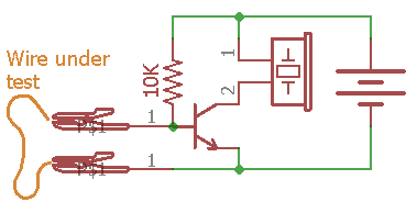 Such an instrument could be made with just a transistor, resistor, and a piezo buzzer. The wire under test overrides the base pullup and keeps the transistor (and the noise) off. This is basically a boolean tester, and is off as long as the wire is << 10K. That’s probably a fine solution, at least most of the time.
Here we go
A more properly over-engineered solution that might detect changes in resistance on the 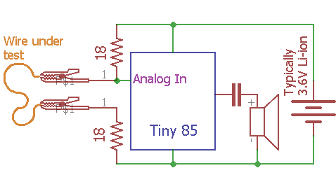 order of a few tenths of an ohm might be built as shown. If we chose to limit the current thru the wire arbitrarily to say 100mA, using say my usual bench Li-ion cell as the 3.6V power source, we’d need about 36 Ω as limiting resistance. If we split that in two, both ends of the wire would be close to 50% of the supply voltage. If we used, say a Tiny 85’s analog input as a sensor (using the default of the power supply as the reference), that would put the ends of the wire comfortably in the middle of the A/D’s 1023 count range. (Reason for a Tiny: A full Arduino at 16MHz is slightly out of spec at 3.6V, though most work fine. Of course there’s no need to power it from a Li-ion cell. But an Atmel (including a Tiny) @ 8MHz is fine at 3V.)
If the Tiny’s code averaged a bunch of A/D readings at init time (done with the wire already connected) it would have a good idea of the voltage to expect at the top of the wire in non-fault conditions (probably saving it as a float). The actual values of the resistors don’t matter, so no precision parts are needed. (They just need to not drift over short times. At 0.1A^2*18Ω=0.18W there’d be a little heating, so a very conservative approach might be to use 1/2 or 1W resistors.)
If the wire were, say 1 Ω, we’d have a voltage divider with 19/37 (0.5135) of the supply voltage at the test point shown. If the wire’s resistance changed by say +0.1 ohm, we’d have 19.1/37.1 (0.5148), for a change of 0.25%, or about 2 counts in the 1023 count A/D’s view. That’s at the ragged edge of what we could reliably see, so a few tenths of an ohm should be visible. Averaging a bunch (20?) of readings (at well under 1 msec each) would get rid of some noise while still allowing pretty fast response. Update: Hmm – I suppose that 0.25% change should be taken of the ~500 counts the non-fault analog reading would be, not the 1023 counts of full scale. That’s 1.25 counts, even more on the ragged edge, though averaging more readings might help. So a few tenths of an ohm is probably still possible.
A likely source of noise/inaccuracy would be the connections between the clip leads and the ends of the wire under test. Some care would need to be taken to not disturb them much during the test. Of course restarting the Tiny to get a new baseline is easy.
The output indication can be anything – it’s just code. With a small speaker, a tone with pitch dependent on A/D difference from the initial condition could be made when the value exceeded some threshold. Replacing the speaker and cap with a piezo buzzer, it could give a boolean indication of exceeding a threshold, or a series of beeps with rate determined by how far the A/D reading was from the threshold.
All hot air for now. I guess I should build one and try it out.
Interesting insight 2/22/21
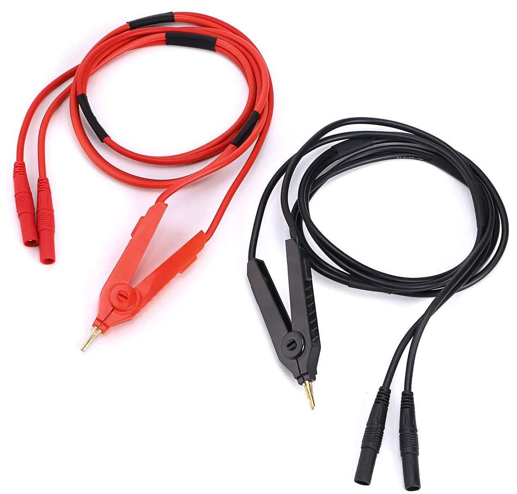 A problem with lead resistance in some battery discharge tests caused me to look up “low resistance clip lead”. That led to discovering Kelvin test leads for milliohmmeters.
I’ve known about 4-wire connections for specialty resistance measurements for many years, and I understand the need for connections to measure voltage separate from those delivering the test current. But I’d never run across commercial clip leads that provided that. And when I first saw them, I thought “That can’t work!”. But a little reflection let me see how cleverly they did their job. Cool.
But wait – there’s more! The light slowly came on that this was almost exactly the potential problem I’d called out above in the discontinuity tester. And that these leads would reduce the problem. I ordered some, and the discontinuity tester has bumped up a couple of steps higher on the list, and might even get built some day!
I recall a tester we had in Telco that would tell you which end of a coax cable was open. That kind of failure was almost always because of a bad solder joint in one of the two connector center pins. The tester just measured the capacitance it saw. The open end would have very little but the good end had all the cable capacity.
You could use a third conductor and form the two wires under test as the top half of a bridge.