It works!

The good news is the discharge board and initial software work!  Here’s a discharge of a 14 cell test battery:

Battery Discharger
version 0.90
Enter number of cells 1-15: Running test with 14 cells.
Test ends at 13.30 volts.
Press Enter to begin
Sample 0 is no load
Starting test - any key to abort
Sample,BattV,Current,cell 0,cell 1,cell 2,cell 3,cell 4,cell 5,cell 6,cell 7,cell 8,cell 9,cell 10,cell 11,cell 12,cell 13
0,18.52,0,1.24,1.26,1.29,1.29,1.32,1.39,1.34,1.32,1.34,1.29,1.34,1.37,1.39,1.37
1,18.07,1591,1.16,1.24,1.21,1.24,1.26,1.32,1.32,1.26,1.29,1.26,1.29,1.32,1.34,1.32
2,17.67,1535,1.16,1.21,1.18,1.24,1.24,1.32,1.32,1.26,1.29,1.24,1.29,1.32,1.34,1.29
3,17.59,1535,1.16,1.18,1.18,1.24,1.21,1.34,1.29,1.26,1.26,1.24,1.29,1.32,1.32,1.32
4,17.52,1535,1.16,1.18,1.18,1.21,1.21,1.32,1.29,1.24,1.29,1.24,1.29,1.32,1.32,1.29
5,17.44,1535,1.13,1.21,1.16,1.21,1.21,1.29,1.29,1.26,1.26,1.24,1.26,1.32,1.32,1.32
6,17.36,1517,1.13,1.18,1.16,1.21,1.21,1.29,1.26,1.26,1.26,1.24,1.26,1.32,1.29,1.32
7,17.31,1517,1.13,1.18,1.13,1.21,1.21,1.29,1.26,1.24,1.26,1.24,1.26,1.29,1.32,1.29
8,17.23,1498,1.13,1.16,1.13,1.24,1.18,1.26,1.26,1.26,1.26,1.21,1.26,1.29,1.29,1.32
9,17.15,1498,1.13,1.16,1.10,1.21,1.18,1.26,1.26,1.26,1.24,1.21,1.26,1.32,1.29,1.29
10,17.07,1498,1.13,1.16,1.05,1.21,1.16,1.29,1.24,1.24,1.26,1.21,1.26,1.29,1.29,1.29
11,16.94,1480,1.13,1.13,0.97,1.21,1.16,1.26,1.26,1.24,1.24,1.21,1.26,1.29,1.26,1.29
12,16.75,1461,1.10,1.16,0.82,1.21,1.16,1.26,1.24,1.24,1.26,1.21,1.21,1.32,1.26,1.29
13,16.41,1443,1.13,1.13,0.47,1.18,1.13,1.26,1.24,1.24,1.21,1.21,1.21,1.29,1.26,1.29
14,15.75,1369,1.13,1.13,-0.16,1.21,1.18,1.24,1.26,1.24,1.24,1.21,1.24,1.29,1.26,1.29
15,15.73,1369,1.13,1.10,-0.13,1.21,1.16,1.24,1.26,1.24,1.24,1.21,1.24,1.26,1.32,1.26
16,15.65,1369,1.13,1.08,-0.13,1.21,1.16,1.24,1.24,1.24,1.24,1.21,1.24,1.26,1.29,1.29
17,15.60,1369,1.13,1.03,-0.13,1.21,1.16,1.24,1.24,1.24,1.24,1.21,1.24,1.26,1.26,1.29
18,15.52,1350,1.13,0.97,-0.11,1.18,1.16,1.24,1.24,1.21,1.24,1.21,1.24,1.29,1.26,1.26
19,15.44,1350,1.10,0.92,-0.11,1.21,1.13,1.21,1.26,1.24,1.21,1.21,1.24,1.26,1.26,1.29
20,15.33,1332,1.10,0.82,-0.11,1.21,1.13,1.24,1.24,1.21,1.24,1.21,1.21,1.29,1.26,1.26
21,15.12,1332,1.10,0.63,-0.11,1.18,1.16,1.21,1.21,1.24,1.24,1.18,1.21,1.26,1.26,1.26
22,14.52,1258,1.13,-0.03,-0.08,1.18,1.13,1.21,1.24,1.21,1.24,1.18,1.21,1.26,1.26,1.29
23,14.36,1258,1.10,-0.11,-0.08,1.18,1.16,1.21,1.24,1.24,1.21,1.21,1.24,1.26,1.26,1.26
Aborted
Done

You can see a couple of weak cells that started to reverse charge, so I aborted the run.

Unfortunately I’ve lost my camera and can’t post pics.  I’ll find it soon…

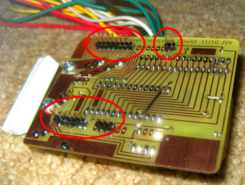
I clipped off the daughterboard and reworked it to use one analog switch chip.  Everything seems to work.  And since the bottom end of the battery is now always at Arduino ground, I can just use an additional analog in to monitor the discharge current, so I don’t even need the DPDT switch I had to trade off how I use the last channel!  And since I’m now taking differences between voltages from ground, I can correctly measure moderate negative voltages – even though the Arduino can’t.

More later (and after I find my camera).  Just wanted to post some good news.

Posted in Discharge tester - PCB build | Leave a comment

New cap for tab welder

The new “Volfenhag” capacitor for the battery tab welder arrived.   Here is it with the old crummy red Pyramid “1.5F” cap.  Doing a discharge test with a resistor, voltmeter and a stopwatch to find RC, it measured at 1.2F.  Not the 3F it’s rated at, but a better percentage than the old cap.

The blanks for the electrodes are pieces of 0.25″ copper tubing with three #14 (maybe 12?) wires stuffed in and smashed flat.  I’ll grind the ends to a point, which will essentially be just the center wire.

I braided some pretty flexible cables from maybe 18 ga lamp cord.  I’ll probably cover them with heat shrink.  If I could get some nice surgical rubber tubing, that would work well.

Remaining is to make some copper straps to parallel the caps, connect the big honking SCR and cables, connect the cables to the sharpened electrodes, hook some kind of switch up to the SCR gate, and try it out! Continue reading

Posted in Battery Tab Welder | 1 Comment

It’s a shield!

The battery discharge tester hardware is essentially complete.   You can see the 15 clip leads that go to the cell connections plus the red/black heavy clips that go to the very top and bottom to carry the discharge current.

The daughterboard with the second 16:1 mux chip is the top layer.  There really is an Arduino underneath.  You can see the pins that make it a “shield” circled on the bottom view.  The Eagle library from SparkFun for Arduino shields put those pins exactly where they needed to be.  There were an embarassment of hacks to the board.

The bad news is that it doesn’t work.  This application of the analog switch is kind of strange – using the chip to connect different cells to ground at different times.  I think it’s all within spec, but the first time I started to hook all the leads up the chips got very hot.  Now it doesn’t seem to work at all.

I have one new chip.  One possibility is to re-hack the board to use a single chip, with one end of the whole battery always connected to ground (instead of using one chip to connect ground and the other to connect the analog input to the cell of interest).  I get an order of magnitude less voltage resolution, but it’s probably (just barely) enough to do the job.  But if there’s something I missed about the chip, that might not work, either.

I’m not sure what my next step will be.

Posted in Discharge tester - PCB build | 1 Comment

Eeprom test

My order of ten 64Kbyte 24C512 I2C eeprom chips from China arrived.  They’re SOIC (small outline IC) rather than the more traditional 0.1″x0.3″ DIP package, and the part number on the chip was unrelated to 24C512 and I couldn’t find it anywhere.  To be confident that it really was the right part, I made up a little breakout board hard wired for address zero, with wires for ground, power, clock, and data.  A bit of telephone station wire connected it to the Arduino for a test.

I found a library to talk to I2C eeproms (bless the open source community!) and after connecting clock and data to analog pins 4 & 5 (?) and a little playing verified that it worked.

I laid out a place for an eeprom on the discharger board, but on reflection maybe didn’t need to.  It was so the board could store cell voltages while a battery was self-discharging (no external load) for a couple of weeks without hogging a computer for all that time.  But you can get about as useful info by fully charging the battery, leaving it on the shelf for 2 weeks (or whatever) and doing a normal discharge test on it.  The cells that have wasted their energy in self-discharge will fail sooner than the others.  Actually, doing that might be a sufficient single test:  You need to know which cells are bad, but it doesn’t matter much whether they’re full capacity but self-discharge quickly or don’t self-discharge but just have low capacity.  Only in true over-engineered style would you need to know the details of the cell’s  shortcomings.  But we do have that capability, just in case.  (You can see a very small daughterboard on the discharger to adapt the SOIC package to the DIP layout I unfortunately used on the board.)

Posted in Discharge tester - PCB build | Leave a comment

Is good enough good enough?

OK – I screwed up.  I missed implementing 2 features in the original board design, and now I’m paying for it trying to figure out how to hack the boards into doing what I need.

The first missing feature was just stupid on my part:  It MUST monitor total battery voltage so it can know when to turn off the discharge relay.  How could I possibly have missed that?

The second one is scope creep:  I put a 0.1 ohm current sense resistor in the discharge path so I could put a voltmeter across it to measure the actual discharge current non-disruptively.  But it didn’t occur to me that I could read that voltage from the Arduino (doh!).  Not essential, but sure would be nice to have.

I’m willing to spend one of my 16 channels to monitor the total battery voltage.  That limits the device to 18V packs instead of 19.2V, but I guess I can afford that.  But if I spend another channel on the current sense, I cut 18V packs out of my capabilities, and that’s really not acceptable.

I can’t just use a couple more analog inputs on the Arduino, since all Arduino A/D measurements are with respect to ground, and the bottom of the battery is usually not connected to ground.  (If I had done that, the 10-bit resolution of the A/Ds spread across a 25V range would put single cell voltage measurements at the very ragged edge of the resolution I’d like.  The boards are laid out to use two 16:1  analog switches using one to connect the A/D input to the top of a cell and the other to connect ground to the bottom of that cell.  I get an order of magnitude better resolution that way.)

I was thinking about adding a third analog switch chip to pick those 2 measurements, but that’s a hassle on several grounds.

So the latest thinking is:  Permanently reallocate one channel to the voltage monitor.  Put in a physical DPDT switch to use the next highest channel (on each of the 2 analog switches) for either monitoring that last cell of an 18V pack OR measuring discharge current.  Most of the packs will be less than 18V, so most of the time I get my automated current measuring.  When I need to do an 18V pack, I’m back to manually hooking a voltmeter up to read the current.  (And I can no longer get automated per-sample current readings for best accuracy of cell capacity.)  But I can live with that.

The down side is I’m at the ragged edge of keeping track of all the hacks I need to make to the boards to implement this.  The fact that the two boards are very similar, but with the analog switch inputs off by one between the boards (so input 0 of one switch goes to the bottom of one cell, but input 0 of the other switch goes to the bottom of the next cell (== top of first cell)) just makes for more brain overload keeping track of which hack wire goes where.

The latest worry is whether I should simplify all the way back to using a single analog switch.  That would dump the second board and make the hacks much simpler.  The bottom of the battery would be always tied to ground.

Life would be much simpler, but I’m back to the resolution problem:  Since max battery voltage is ~25V (for overcharged 19.2V pack), I have to scale the input voltage to 25V full scale.  The 10 bits give me about 0.025V per step.  By subtracting the absolute voltage at one cell top from the abs V of the next cell top I get the cell voltage of one cell.  The range of voltages of interest for one cell are ~1.3V-1.0V.  That’s about 12 A/D steps covering the whole range.  Considering the usual +/- 1 LSB, I have maybe 10 steps to cover hot-off-the-charger to end-of-service.  Is that enough?  Well, I suppose so, but it’s pretty coarse.

So the real question is:  Is (barely) “good enough” good enough to let me do the major hack of simplifying the design back ot a single board?  Or is the challenge of making the more elegant design work worth the extra hassle?  Ugh.

Posted in Discharge tester - PCB build | Leave a comment

New cap on its way for battery tab welder!

The capacitive discharge battery tab welder (inspired by various web postings including ledhacks and the seminal philpem note) has been sort of on hold since I discovered the nominally 1.5F cap I bought measured at 0.3F.  I had even made up suitable cables and hacked some wire and copper tubing into electrode blanks.  But I was afraid the cap wouldn’t deliver enough energy to do much.

With the interest in battery rebuilding at Workshop 88, I was inspired to get things moving again, so I ordered another 2F cap.  Someone had said he had good luck with a Volfenhag (which the new one is) and poor luck with Pyramid (which the old one is).  I just got notification that it had shipped.  Watch this space for news!

Posted in Battery Tab Welder | Leave a comment

PCB progress

There were some bad copper bridges on the daughterboard from the “fuzzy” area spotted by someone at the PCB making demo.  (I suspect it was a small bit of crud holding the artwork away from the board.)  I opened those bridges with a combination of Dremel and Exacto knife.  There were also some small bridges on the main board.  That’s quite unusual – my processes almost always produce clean boards.  Anyway, those are cleaned up as well.  Boards are a little ugly, but should be functional.

The daughter board is drilled, the 28 pin socket soldered in, and I found some suitable pins (pulled from an old wire wrap board, I think) for connecting it to the main board and soldered them in.  I think the daughterboard is ready to go.

The main drilling run for sockets, most components, clip leads to the cells and pins (both to daughter and to Arduino) is done.  I still need to drill some bigger holes for the binding posts for the load resistor and the larger cables for the main discharge current.

A significant remaining task is figuring out what I’m going to do about hacking an extra 4 switches on to the (main) board for discharge current and overall voltage measurement.  I’ve drilled a couple of additional holes for jumpers for control signals and analog signal to the same analog input the cell measurements use, plus power and ground.  I’ll also need the voltage divider resistors and some kind of socket for the yet-to-be-specified IC.  Might well be another small board glued on top of the main board.  In any event, I probably shouldn’t mount the daughter until I have these still-open design issues resolved. 🙁

Pictures needed, too.

Posted in Discharge tester - PCB build | Leave a comment

Discharger PCB hacks

I never think of everything in time.

The analog mux chips give me 16 channels to connect to individual cells.  For NiCd, that’s a max of 16*1.2V=19.2V packs.  That covers almost all battery packs – great.

But the discharger also needs to be able to look at end-to-end battery voltage to know when to turn off the discharge relay.  I need to put a divider across the (heavy) discharge leads so we have a scaled voltage to measure that’s never > 5V.  But I can’t just leave an extra analog input permanently connected to the divider tap and set up for cell #0 to get ground patched to the bottom of the battery:  That would work for the measurement, but for other cells, ground could be many volts above the divider tap – probably blowing out the analog input!  So I have to be able to switch both ground and an mux input connected to the divider tap – just like I do for all the individual cells.

I’ve considered spending one channel of my 16 for that.  It would take some hacks to the PCB – ugly but doable – and cost one cell of capacity.  15 cells is still 18V, which still covers almost all battery packs.

But I also cleverly put a 0.1Ω current sense resistor on the board.  The original plan was to put a voltmeter on it to get a reading of actual discharge current.  But much cooler would be to have an A/D read it.  That would not only be simpler (no extra step with a voltmeter), but it could read the actual current at each sample, giving a more accurate cell capacity measurement.

BUT – that would take yet another channel.  I really don’t want to go below 18V.  So I’m looking at somehow sticking 4 more SPST switches on the board to pick up those 2 extra readings.  Part of why I chose the DG406 analog switch I chose was that the analog range was independent of the logic control voltage.  I don’t think I can just use a 4066 or something because the voltages are too high.  There are other smaller mux chips in the same family as the one I used (including its 44V safe input range), but they’d require yet another order to DigiKey.  I guess I really need to think about that some more.

(For reference:  The control signals are always normal 5V logic from the Arduino.  Since all analog measurements are with respect to Arduino ground, we have to connect the bottom of the cell being measured to “ground”, as well as the top of the cell to the analog input.  That means other mux pins may be up to 19V away from “ground” at various times.  I think the 406 can handle that, but I guess we’ll see the first time I fire it up 🙂 )

Posted in Discharge tester - PCB build | Leave a comment

Discharger Arduino code thoughts

One of my biggest fears for the Arduino code is that a bug will turn on inappropriate analog switches, resulting in a short or other undesired connection, probably damaging either the mux chip or the Arduino itself.  To help avoid that, I should probably have an “all off” function that is called after every voltage measurement.  Before each measurement, a function that turns on just the desired connections should be called.

The turn on function probably needs 2 params in:

  • type (total V, current, cell V)
  • cell # (only used for cell V)

Code is pretty simple:

  • setup – port inits, etc
  • initialize/config dialog over serial port
  • wait for start command
  • maybe initial open circuit voltage?
  • turn on relay
  • main loop
    • loop thru N cells, measure each voltage
    • measure current
    • measure total voltage
    • spit out this cycle’s measurements to serial or eeprom
    • if total voltage < threshold, turn off relay, end
    • sleep
  • end code – maybe some arithmetic?

Hmm – does the “measure the voltage” function need to take an input parameter of whether to use 5V as its scale or use the 2.4V Zener reference voltage I supply?  The cell measurements are all nicely under 2.4V.  The current sense is 0.2V at 2 amps, so that’s small.  And I guess I can scale the total end-end voltage to whatever I want – so I guess that one’s OK as well.  I suppose I could get twice the resolution for current sense if I switched to the internal 1.1V reference voltage for that measurement.  For the 3 lines of code, it’s probably worth it.

Posted in Discharge tester - Arduino and perl code | Leave a comment

Notes for installation of solar panels

This summer I was seriously considering putting ~2.5KW worth of PV solar panels on the roof of the house and the garage.  (That was all that would fit.)  I was working with a guy from Earth Wind and Solar, and had pretty much spec’ed things out.  The state and federal incentives came to about a 60% discount on the job – how could I refuse?

This post is just to move an earlier page I had made with some careful measurements to help see what would fit.  That page was the only other item on my first “projects” placeholder page, so moving it let me point the link on my home page directly at this project blog (or whatever it is).

Unfortunately, my wife had aesthetic and other concerns I was not willing to fight, so the project never happened.

The original page is here.

Posted in Solar Panel Installation Notes | 1 Comment