
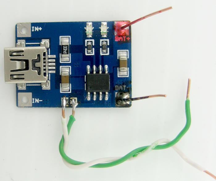
 I got a couple of cheap ($1.29) 1A USB LiPo chargers since I’m doing more and more LiPo/LiIon powered stuff. I mostly discharged a recycled 18650 cell for a test load and it looks like it does charge at nearly 1A. Two LEDs – red charging, green (mine is blue) fully charged. Seems like a pretty ideal cheap device. (But see the comments for significant warnings!)
Since I use a variety of cells, I wanted to be able to charge at 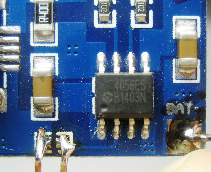 under 1A. Most such charge controllers have a single resistor that programs the bulk charge current, so I looked for the datasheet to find what values I’d need for the charge currents I wanted. The chip is marked 4056ES, and there are charge controllers with that number – but they don’t match this package layout. The Ebay ad was titled “5V Mini USB 1A Lithium Battery Charging Lipo Charger Module for Arduino A866”, but I couldn’t find anything under A866, either. It says RD084DY002 on the back, but that’s not helpful either. Rats. (But see update!)
I replaced the likely candidate programming resistor – 1.2K stock – with some leads so I could determine values experimentally. Here’s what I found:
  1 A   1.2K (stock)
~480mA  2.1K
 400mA  2.6K
 200mA  4.9K
 100mA  9.3K
  50mA 18.5K
Now I’m all set for when I need to deploy one.
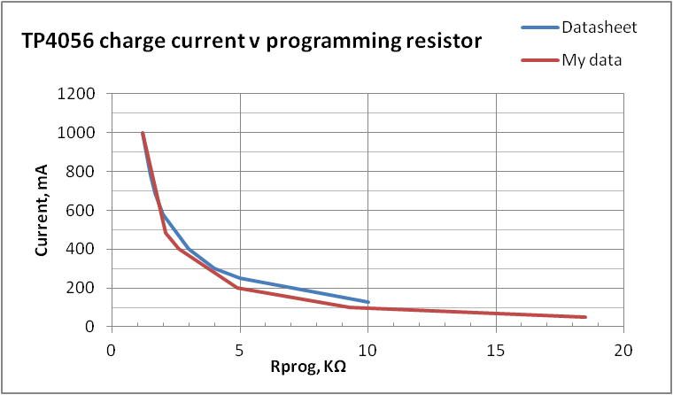 Update 10/8/14: Thanks to Vitor, we now know the chip is a NanJing Top Power TP4056. I did a comparison of the programming resistor vs charge current info from the datasheet, and my empirical data seems reasonable. Thanks, Vitor!
Update 12/1/14: Looks like it’s actually a knockoff of the TP chip, and a possibly dangerous one at that. Thanks, Halo!
Update 11/22/16: I’m trying to design a quick, cheap, simple test jig I can run a bunch of these charger modules thru before I hand them out at a battery technology for hobbyists class. I really don’t want to hand out bad chargers!
If they come with programming resistors for 1A, how about this:
- With input side disconnected, connect battery side to bench power supply at maybe 4.4V and watch current. If significant current flows, module fails. (What’s significant? 1 mA? 10mA?)
- With (bench supply above removed or turned down and) input connected to power – say a 2A USB wall wart charger, running thru a Charge Doctor to monitor current: Connect a 4 ohm, 5+ watt resistor from battery output to ground and put a good voltmeter across it. At 1A, that should give around 4V, and “charging” should continue normally. Verify charging current with Charge Doctor. Obviously fail if not right.
- With load resistor, voltmeter, and power still connected, connect a bench supply (good for > 1A) across the resistor and slowly crank the supply up, watching the good voltmeter. (Should probably verify first that the bench supply doesn’t do anything bad if voltage impressed across its output is greater than the voltage it’s set for.) Use Charge Doctor to verify that charging stops at 4.2V. Voltage should stay quite constant – though now the bench supply is supplying the current. What is fail level? >4.25V? or <4.15V? Hmm – I guess we should also verify that the charger doesn’t do anything bad when its output voltage remains high after it stops delivering charging current.
Does that sound good? Any other thoughts or warnings or improvements?
Update next day: Tried 2 modules, one new stock, one with resistor to charge at 42 mA. (Used 94 ohm load for the second.) Both behaved as expected, and passed all tests. Both showed 0.2V or a little less hysteresis between “done” (green LED) and charging, and went back and forth smoothly. Charging current seemed to tail off near 4.2V.
So – modules behaved OK, and tests – including the eyebrow-raising connecting a power supply to the output of a battery charger – seem to work OK. Comments/suggestions are still more than welcome.
Thanks for some info and test about it, I bought mine from AliExpress
http://www.aliexpress.com/item/-/2012679197.html
You may want to look here:
http://budgetlightforum.com/node/13913?page=1
The IC used is a TP4056: http://dlnmh9ip6v2uc.cloudfront.net/datasheets/Prototyping/TP4056.pdf
Thanks so much for the info! I’ve updated the post.
Jim
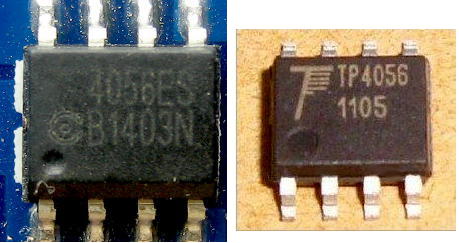
4056ES marked chips are not orginal TP4065 from NanJing Top Power. Instead those are clones. NanJing Top Power chips have their logo on the chip. I’ve seen clones marked TP4056 (no logo), 4056, 4056ES or blank. Some of the clones do not behave quite the same as the original. Some dangerously overcharge.
Thanks for the info, Halo! Here’s a pic of one of mine, plus one (from dear old Google Images) that matches the logo in the datasheet Vitor linked to. Looks like mine are clones! I don’t recognize the logo on mine, tho.
I obtained these same PCBs across three orders from three different AliExpress vendors, and each batch of them has a different IC logo – same TP4056 part number. The first batch, which cost the most per unit (slightly over a dollar per) has no logo on the IC and performs as intended, this is what turned me on to finding more for additional projects. The other two have logos – one with the same dot in the middle of a C, but somewhat more vertically compressed than the image you have here, and the other with “TPower” above the chip number and datecode. The TPower labelled ones (from the vendor I obtaiuned them from) had the blue and red leds swapped, but that’s not a function of the IC. All the other components are the same ratings between them – current resistor, caps, etc.
Both of these other types short out once a battery is connected which needs charging. The only difference on the PCBs is the manufacture of the IC.
If I use a Charger Doctor (voltage/current metre for USB), I’ll have good USB voltage and no current to start before connecting anything, and once the battery is connected, the whole system resets because the instantaneous current draw is so high it drops the input voltage by 4 volts (as viewed on a scope in realtime). A second later, it recovers, and repeats the process. If left alone, eventually the battery will take on a charge, but this isn’t how it’s supposed to go down. The duff units behave the same way whether the Charger Doctor is inline, and with different USB power supplies, as well as different batteries (the combinations of which work fine with the known good PCBs).
Because I shun just tossing things, I have on order a lot of the TP4056 ICs to rework the PCBs. As I have no way of knowing the new ICs (from yet another vendor) are legitimate, I have less than a 100% expectation that this will be successful — but you can bet I’ll be waiting on the results before providing vendor feedback on the replacement ICs.
On a few of the duff modules (which sadly significantly outnumber the quantity from my good order), even without USB power, if I connect a battery, the charging or fully charged indicator LEDs will light up, and the battery voltage will be present at the input. Neither of these is good – the counterfeit chips shorting the battery to Vss is outright dangerous. If you’ve got one of these modules, before putting it into service, ensure that this isn’t the case with yours: without USB connected (or whatever supply you intend to use), clip your DMM to the solder tabs at the corners on the USB side, then connect a LiIon cell to the battery tabs. If you get voltage on the USB side, do not use the module.
Thanks for the warnings, splud! I’m considering getting a bunch of these as a handout for a ‘battery tech for hobbyists’ class I’m planning at our local hackerspace. Now I’ll be sure to test them all before I give them out!
Hi!
I also bought couple of these modules from e-bay. Both modules have squished “C” logo chips on them. The LEDs are also swapped. When I connect USB cable to module, but without battery, the red LED (stand-by) is on, but the blue LED (charging) is blinking with rate of about 3 times in a second. This seams to be normal. I measured voltage in USB end, when connecting battery to the module and it was 0V. Again seams fine. This could mean that some of these modules are bad and some are not. So everyone should check the chips before using regardless of IC manufacture logo.
The only weird thing is that blinking of blue LED produces quiet audible tapping like noise presumably coming from IC. When I connect battery it stops and blue LED is on while charging.
Hi all,
seems I have fake TP4056 chips, they do not terminate charging at even +4.26V, charging current still >40mA.
Do you know how I can modify the module to get it as close as possible to4.2 or even 4.1V
thanks
bob
Hi Bob,
I think the final cutoff voltage is determined internally in the chip, so I wouldn’t expect there’s much you can do to modify it. That said, it might be possible to replace the battery with a (big) resistor or maybe an adjustable current sink to try to find what voltage the chip finally cuts off at (if it ever does!). If it’s significantly above 4.2, I’d try powering the device with a bench supply and watching whether the “cutoff” follows the input voltage. If it does that, I’d completely give up on the device. (Or, if you’re as industrious as splud above, buy some replacement chips and rework the boards!)
Jim
hi,
just wondering, when i connect the battery, without connecting USB power, I do get a voltage reading at the input of 0.07V, no lights light up. Is this negligible and can I assume my board is safe or not? I have one with overcharge protection btw.
thanks for this post btw
kind regards
Hi Ido,
I just tried it with a module that seems to be working. I also got no lights, but only got ~1mV on the input terminals. That said, seeing a small fraction of a volt leaking back to the input terminals wouldn’t set off any red flags at all to me.
I guess I’d just hook it up to a source and battery and keep a close eye on it for the first charging cycle. If it ever runs the voltage across the battery above 4.2V, I’d get pretty spooked about the unit, and seriously consider just discarding it.
With these units so deliciously cheap, but so frustratingly likely to be no good, I’m tempted to try to set up a simple charger testing jig. With 4W to dissipate, it would have to be more than just a normal pot. Maybe just a pot and a power transistor? But I don’t even know if that would let you spoof the charge controller well enough to investigate its behavior. Anybody out there ever try something like that?
Jim
Thanks Jim,
Did a full charge today, hooked up my RC watt meter, and the voltage stopped at 4.2, after seeing the A drop.
It is indeed stupid that fake ones can be no good, why produce it, if its useless. They are very cheap, its even easier for me to create a parallel charging unit with individual chargers, then being creative with some wires.
found some fake tp4056 chip ( no logo) have a faulty enable input , so when enable is low it still is providing power on the bat pin
Tpower logo tp4056 that i have tested to date -( about 10 units ) have worked well , and shut down when bat is fully charged
Thanks for the additional data points, longpole001!
hi longpole001,
can you provide me with a link or info to the original ones with the tpower logo?
tks
lawrence
A possible alternative is to just use known-good chips and order PCB boards from China, use also an assembly company. It’s more work and cost than 75 cent modules on eBay but then you wouldn’t hand out bad modules by mistake.
A MCP73831T-2ACI/OT is 48 cents in qty on DigiKey, the datasheet typical application circuit requires at minimum three jelly bean components (pennies), a set of 100 1″x1.5″ PCBs on PCBShopper is 61 cents a piece, and assembly is $1.84/board. Or DIY with a hot plate/toaster oven. So for 100 quality chargers you would pay between $2 and $4 each.
It’s up to you to decide if that’s worth it or not, but this article has convinced me to pursue this path for a product I’m building, rather than integrate pre-made but questionable modules as I had been planning to do.
I thought about buying some genuine Nanjing TP chips but I contacted the company and there is no way to buy them either from the company or from any distributor in the States. So you have to use an alternative like the one mentioned.
Hi Christopher,
Thanks for your comment. Of course you’re absolutely right that the right way would be to use legit components, and if I were doing this commercially, that’s exactly what I’d do. But for the 5 or 10 units I need for a class at the hackerspace, the extra work of making up boards would probably be a showstopper. The half hour of testing to verify that the cheapos worked (at least on day 0!) is an acceptable cost.
Interestingly, there’s another (actual commercial) project I’m working on containing Li-ions, and have an initial lot of “real” charger chips for it. (I chose MCP73113s.)
If some of this discussion has helped clarify a way forward for you, I’m delighted. There’s nothing like open sharing of ideas and experiences among techies to help us get to “Success!” with a couple fewer cuts and bruises.
Hi,
could you please explain how you measured the max. charging-current?
I ask for the following reason:
I ordered the charger boards from and planned to use them with 400mAh LIPOs (single cell).
For this I thought I’d have to replace the Rprog to cut off the charging-current at 400mA or a little lower at 0.7c.
My problem now is, that I can’t get more than 500mA out of these chargers – even with the original setup. When I measure the current to the empty battery I get a dropping curve starting at 500 or 400 mA reaching zero when the battery is full.
Could it be, that the battery limits the current?
link got lost:
https://www.amazon.de/XCSOURCE-St%C3%BCck-TP4056-Charger-TE584/dp/B01M1346R5
Hi Tom,
Sorry for the late reply. The best way to measure charging current is at the source feeding the charger. (Ignore the few mA the charger consumes.) If you try to measure current in the obvious place – between the charger and the cell – the voltage drop across the resistance of your ammeter increases the voltage the charger sees, possibly causing it to limit current. (Google burden voltage.) If you must measure after the charger, measure the voltage across a known, very small resistor in series with the cell. I stock 0.1 and 0.01 ohm resistors for this. Of course be sure to use a 4-wire hookup: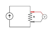
At 1A, a 0.1 ohm series resistor will add 0.1V to what the charger sees – which is a lot. A 0.01 ohm would only add a hundredth of a volt – which is tolerable in most cases.
Especially if the cell is partly charged or has high internal resistance, the voltage the charger sees may be high enough to limit the current it chooses to provide. The charger should give full current at between maybe 2.9 and 3.5V. (Lower it may refuse to charge; higher it may start tapering charge current.) To ensure the voltage it sees is low enough to get max bulk charge current, try making it feed a carefully chosen resistor instead of a cell. Say we’re expecting 1A, and plan shoot for 3.2V. A 3.2 ohm resistor would just do the job. (Watch the power rating – that will be 3.5W!)
The challenge with this method is that when you start out – with no current – the voltage across the resistor will be 0V, and if the charger has any decency at all it will refuse to charge what appears to be a dead, shorted battery. If you have a cell (or a bench supply) that will supply that 1A thru the resistor – even for half a second or so – so the charger sees 3.2V to start with, you can juggle the connections to get the charger started so you can proceed to the real job of making your measurements!
I hope that helps!
Jim
Hi,
Nowadays, it seems that the most common clone of the TP4056 (from NanJing Top Power) is the TC4056A (from Shenzhen Fuman Electronics).
It is dead cheap (a charging board can be bought for less than $0.30) and seems to work, but I would love to know its true colors (charging curve, reliability, etc.).
So would I! But in these days of Chinese ripoff chip clones and forged markings, it’s hard to tell what you’re getting. It’s a real dilemma for me sourcing boards like this as handouts for a class on battery technology. I’m happy to do a quick “does it even work” test on the small numbers I need, and I suppose I should even extend that to an hour or day of burn-in. But the serious talk about trust and long term reliability for something that can actually cause damage is another important part of the class.
I also purchase the boards from amazon from Xsource. The first test I did was put a discharged battery on the charger. The charging current is supposed to be about 130ma but it was over an amp.
The charging current was over an amp. This is dangerous and I wonder how many people assume the board just works properly.
A good way to measure the charging current is measure the voltage at pin 2 of the 4056 then use the formula (Vmeasure/Rprog )x 1200