
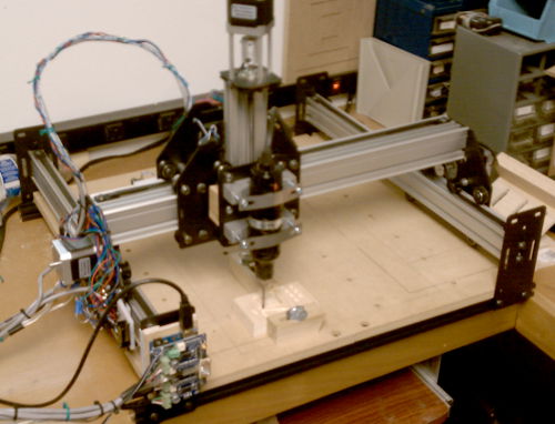
 Now that the W88 Shapeoko 2 (graciously donated by Inventables) is mostly working, we tried some test cuts in various materials. All were done with my old Dremel and a 1/8″ upcut end mill (WRONG: downcut; see update at end). We ran a nightly build of Universal Gcode Sender 1.0.8 (to avoid the Reset Home bug in 1.0.7) with grbl0.9g on the Shapeoko2’s Uno. Thanks to Scott for his help and consultation!
We had a lot of trouble with unexpected hard limit alarms until I disabled the limit switches in grbl. Looks like picking up noise on the limit switch wires is a common problem. We suspected electrical noise and tried plugging the Dremel into a UPS, but that didn’t help much. Next steps I’d suggest are 330Ω pullups (instead of depending on the ~20K internal pullups) and maybe 0.1μF caps to ground on each limit input, along with running shielded wires. Not sure whether to use shielded 2 conductor or just thin coax.
All the cuts were with hand edited Gcode tracing out a 1″x1″ square, with various directions, depths, passes, and feed rates. There’s lots of lessons in these cuts; I’ve only picked some highlights here.
“Foamie”
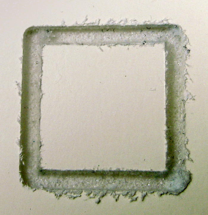
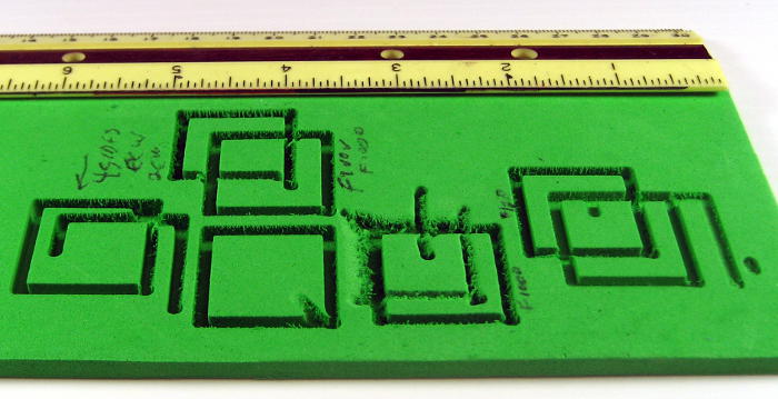 A dense flexible craft foam I seem to know as “foamie” cut pretty well. This piece was 5mm thick. One of the things we learned early on was that the wall of the cut where the cutter was going in the feed direction (maybe conventional cutting vs “climb cutting”) was much smoother than the other.
 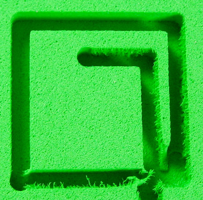 You can see that effect in the far right vertical cut here. The far left cut shows that by having the cutter retrace the path in the opposite direction, the sloppy wall was considerably cleaned up. The rounded outside corners reflect the radius of the cutter.
Foamboard
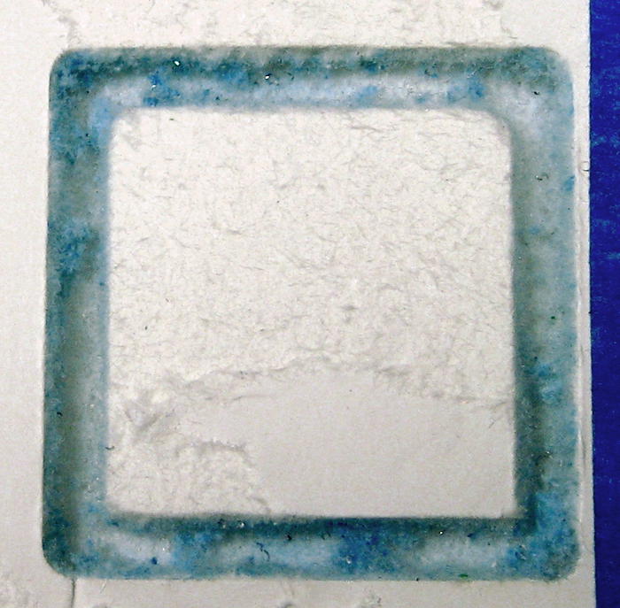 I had high hopes for foamboard, but although it cut easily, the top surface tore out badly. We tried 2 approaches to reducing the tearout – both pretty unsuccessful. Here’s the result of covering the surface with blue painter’s tape and cutting through that. Bits of tape are obvious in the bottom of the cut. But the real problem was that the tape stuck so aggressively to the nice outside finished surface of the foamboard that despite careful removal, it destroyed the surface. There’s evidence that the cut edges were protected and cleaner, but tearing off the good surface is a show stopper. It could be that other flavors of tape and foam board might play more nicely together.
 This was a failed attempt to protect the edges by taping a thin sheet of aluminum (pop can) over the surface. The aluminum didn’t stay in intimate contact with the surface, and so protected it little, if any.
 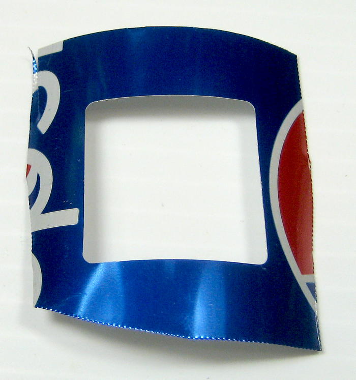 The results were about the same as with no protection – unacceptable. This is probably what chipboard would look like with this cutter. I think the blue here is from the paint on the can, and you can see little bits of aluminum that didn’t get cleaned out. On the plus side, the aluminum cut beautifully.
Foam insulation board
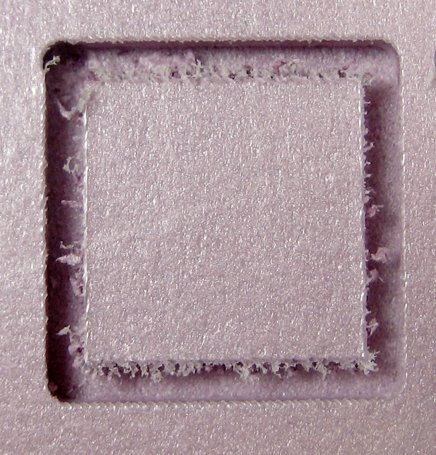 This is a classic material for hacker CNC machines. It cuts easily and is cheap. (A 4’x8′ sheet of 1″ thick board is maybe $15 at Home Depot; pink and blue are just different brands.) I think I ended up with good results at 1500 mm/min (1″/sec). This was an early cut when we were working through the “smooth side/ rough side” behavior. The cutter spins CW (looking down) and this cut started in the upper left and went across the top, down the right side etc, so the outside wall was cut the good way, with the fuzzies on the inside wall.
 To verify the dependency on feed direction, we tried going the other direction. This one started lower right, went up then across the top to the left. Sure enough, the fuzzy side is now on the outside. This one was also testing whether reversing the path would clean up the bad wall. After it got back to the lower right, it went the other way (left across bottom) half way. The cleanup pass is quite effective.
Plastic badge material
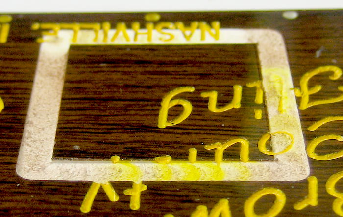 One of the obvious target materials is the stuff name badges are often made from. A thin layer of one color is laminated over a substrate of another; cutting through the top layer exposes the lower color. The clunker 1/8″ mill we had isn’t useful for reasonable size badges/signs, but here’s the result of a quick test on an old badge. Only after cutting did I realize that the original badge – with white substrate – had been engraved and then the (white) groove filled with yellow paint! That (well dried) paint tainted the cut. The bottom surface was much rougher than I’d like, though that probably won’t matter with a much smaller cutter. I suspect the roughness was due to melting from too high spindle speed. You can also (barely) see that the cut was deeper on the left than the right. Just a reminder that when you make cuts this shallow having the spoilboard dead level is critical!
Acrylic
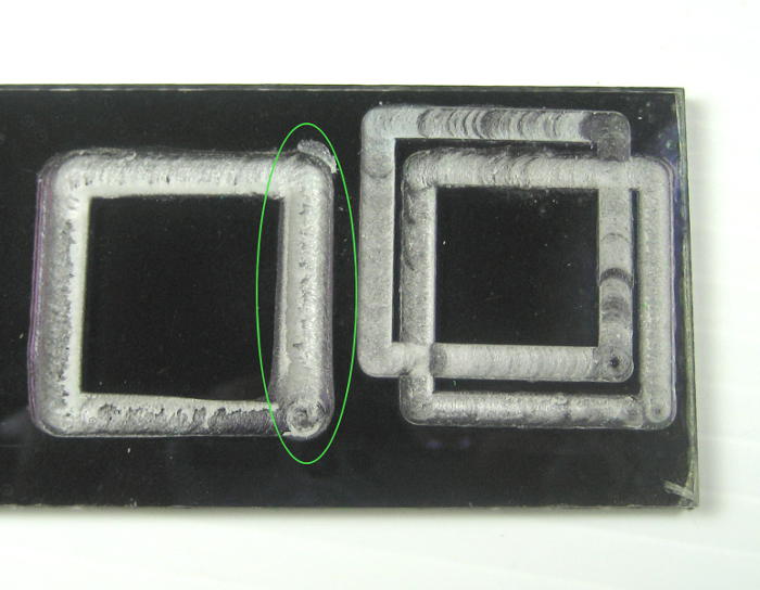 I really hoped to be able to do better than this with plexiglass. The spindle’s pitch change told us it needed a pretty slow feed speed. But with the Dremel at maybe 10K RPM, melting was a real problem. The circled path is way larger than the diameter of the cutter. It was essentially being milled out by the big blob of melted plastic on the end of the cutter! This makes me even more critically interested in seeing how a much lower spindle speed – with closed loop speed control able to crank more power in at that low speed – would do with plastic.
Chipboard
I brought several samples of chipboard, but after the nasty rough edges on the foamboard, I didn’t even bother cutting any. I’m almost certain the results would have very similarly disappointing torn out edges.
That said, I suspect strongly that the problem was in using an upcut spiral end mill. I wondered initially why anybody would want a downcut – since it would force the cuttings into the cut rather than lifting them out as the very reasonable upcut mill would do. But now I see: With soft material like this, dealing with the chip load in the cut would probably be worth it to get a nice clean cut at the top surface. The idea that a downcut was suitable here was reinforced when as I looked on Ebay for downcut mills I came across a set of “Luthier’s” mills for doing inlays. They would obviously care about clean edges – and those mills were downcut. Guess we need some of those, too!
Update 9/23/14 (from 9/12/14): Rats. The endmill used for all the cutting above was in fact a downcut mill. I was just being dumb when I first looked at it.
The very sad consequence of that is that my hope for better surface edge cuts with another mill were unfounded. I got those bad edges with the mill I thought was what I needed. Bummer.
Someone suggested that there’s another kind of downcut mill, with additional relief that would work better. Could be. The range of choices in cutting tool design, geometry, and material along with the real fundamentals of tool speed, feed rate and depth of cut multiplied by the variety of materials to be cut and results desired produces a mind boggling array of choices, with only a few being near optimal. It looks like a year and thousands of dollars in education to run a milling machine sensibly as a beginner. There must be an easier way. I guess the hope is that someone with the necessary education and years of real world experience will write a Dummies book for the rest of us.