
 Just a quickie, but it seems to delight me. I finally got around to making up a little bunch of generic Tiny85 boards so I can knock out some simple projects. They’re a lot like the I2C slave boards for the dollhouse, but have all the pins brought out and have a 6-pin ICSP header so programming is easy. I laid out the board several months ago, but hadn’t gotten around to making any.
Of course, the first one didn’t work. I’m pretty good about putting a mark on the PCB for Pin 1 on ICs and connectors, but I missed it for the Tiny on this board. (It’s fixed now 🙂 No problem – the board is so simple I can reverse engineer it visually. Let’s see – I always put a pullup on the RESET pin, and there are only two 1206 pad pairs, and that one is a jumper, so the pullup must be here – and that goes to the Vcc pin, which is pin 8, so the chip must go this way. Done! I put all the SMT parts down and reflowed it – and it looked about perfect. A couple of minutes to hand solder the header, and it was time to test.
But it didn’t even get as far as running avrdude for a signature check. As soon as I plugged it into the Arduino ISP, all the lights on the Arduino went out. I held it to my lip, and the Tiny was fairly warm. Not good. Then I proceeded to make myself crazy trying to more carefully reverse engineer it visually. Was the header layout backwards so the pins came out the back of the board? Did I actually lay out that nice big ground pad wrong?
When I finally looked up the original Eagle layout files (like I should have in the first place!) it became frustratingly clear: I didn’t put a pullup on RESET (it’s not really needed) – and those pads are for a cap across +5/Gnd, not a resistor! And sure enough, my reverse engineering based on the non-existent pullup led me to put the Tiny in backwards! Rats.
I made up another board (correctly, this time), and it worked first try. Same for the next one, and the same for another set of 3 I reflowed all together. So I had 5 working boards plus the bad one (now with an X on the back, since they all look very similar) as a continuous reminder of my sloppiness. Guess I better fix it. (The picture was taken before the fix. Can you find the one with the Pin 1 dimple opposite all the others?)
Hmm – it really should just be a 5 minute job with the hot air station. But did I fry the chip? (Fires up the hot air.) Eight minutes later, reusing the original Tiny, I had another working board! To reward the board for surviving being powered up with the chip in backwards, I even replaced the wimpy green LED with a nice bright red one. Now I not only have 6 boards at the ready, but no longer have the reminder dud staring at me. (And I got to wipe that big X off the back!)
Applications
What will they be used for? One of the first applications will be a beeper to remind me the hot melt glue gun is plugged in. When I need it I plug it in and, having better things to do than watch the glue melt, walk away. I usually come back a few minutes later to use it. But sometimes it’s an hour. And once it a while it’s many hours. Ouch. So one of the Tinys will wait until the gun is hot (open loop timing), and sound a piezo buzzer once. A minute later, 2 beeps, then 3, etc. That should work well. (When I get around to making it.)
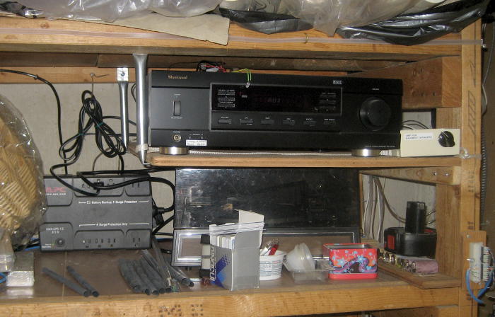
Another application will be making the house stereo amp more robust. The dumb Sherwood RX-4109 that lives in the basement (always on) and drives speakers in the kitchen, living room and bedroom has a ‘soft’ power switch that defaults to OFF after a power cycle. Since the music it provides is also my alarm clock, the priority of a fix jumped much higher on the list after I overslept the morning after a brief power outage shut it off.
I’ll decode the Power ON sequence from the Sherwood’s IR remote, program a Tiny to reproduce that signal to drive an IR LED taped to the front of the amp, and have the music startup script tell the Tiny to send Power On to the amplifier every time some music starts. Overkill, but at least it should always come back after a power failure. Since the music script is on the main PC, I’ll have to invent a channel to send a message to the home automation system which can in turn actually operate the IR sender Tiny. Several steps, but it will be nice to not have the (upstairs) music fail after a power failure.
 Update 10/3/14: Not related to Tiny85s, but just to the dumb Sherwood receiver: I won’t need this Tiny app, as the problem has been resolved. Someone donated several dead UPS units to W88. I brought an APC BackUPS 350 ES home and (as expected) the only problem was a dead battery. In an interesting lesson about industry standard battery sizes, I was able to remove the stock 3 A-hr 2.6″x5.25″x2.7″ 12V SLA battery, and by breaking out a bunch of support webs, drop in an old, much larger 7.2 A-hr battery that fit perfectly! It had been removed (I think) from a B&D string trimmer and found to only have 2.4 A-hr capacity. That’s plenty for this app, and the battery worked, fit, and was free. The receiver is now on its own UPS, and should survive at least short outages without turning off. A perfect, free solution!
Another possible application will be at least doing initial datalogging to see how much power I can get from a small solar panel in a tree where I really want to put a camera looking at the house. Solar (or possibly wind?) is the only way I can power it to take a picture every few minutes and radio it back to the house. Doing this initial energy monitoring/logging has been on the list for oh, maybe 5 years. Maybe these Tinys will let me make it happen.
But just having that little stash of Tinys there – each one eagerly awaiting its chance to serve – gives me a little delight each time I see it.
Really liking this one. You need a fixture with pogo pins to eliminate that ugly protruding six pin header. Hope to see this board in your next tiny85 class.
The top left board looks a little charred.
Yeah, I don’t like the header either. I bought some real pogo pins a while ago for cases like this – but it was easier just to put the 6-pin on than build a nails jig. I suppose laying out the 6 pads – but no holes for pins – and making up a hand held probe with the 6 pogos at the end with a pigtail to a standard 6-pin male would work. My hand is still steady enough to locate on those pads pretty consistently. But after each programming cycle during development, I’d have to switch to other power arrangements. With the header, the Tiny is still nicely powered.
Hmm – I suppose I could add 2 non-pogo pins and drill 2 holes and avoid any possibility of slipping. I guess I’ve just described an upside down, hand-held bed of nails.
My plan for cases when the ugly header was actually in the way when the Tiny was in its final home was to just cut the pins off. That should work fairly well.
But what I’d REALLY like is to put the 6 pin header on a little island off one end of the board and just cut the whole thing off after it had final code. I picture the isthmus to the island only wide enough for the 6 traces, but I suppose that’s overly fancy: Just whack off the whole end of the board with the header when it’s time.
I might make some up for the next ’85 class, but it kind of feels like the lowest barrier for students to feel like they could actually use a Tiny is a DIP on a breadboard. Maybe the way to go would be to run a class on surface mount soldering and have the students
white washmass produce a bunch to be sold for the dollar or two in parts.The top left one was in fact the first, and not particularly charred. If you look closely, you can see the dimple is on the opposite end from the other 5.
Pingback: Hot melt glue gun timer | Jim's Projects