
Wow – I wasn’t planning to make this. But as I fantasized about just building a simple discharger while struggling with 1-cell problem on the big 18 cell discharge tester, it sounded too simple to resist. I could get to a couple of analog inputs and ground with a mini-shield just on one side of an  Arduino. (And I seem to like mini-shields.) And a MOSFET instead of a relay would make it simpler and more robust. It sounded so simple I just made it up on perfboard rather than laying out a PCB.
The extra juicy bit of simple was realizing that the Drain-Source resistance Rds was pretty constant, and for this MOSFET was in the neighborhood of what I needed for a current sense resistor. If I put the MOSFET at ground and measured the voltage on the Drain, I’d have the current reading – for free! And it doesn’t take a fancy 1% 0.1Ω resistor – as long as it’s a fairly constant value, a calibration constant in the code will deal with it.
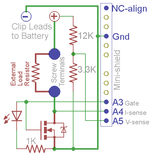 It uses screw terminals to connect an external load resistor like the big discharger, but stayed very simple with just a single pair of clip leads for the single cell. An LED on the Gate (really on the Arduino pin driving the Gate) to show when it’s discharging is nice. The 1.1V internal reference on an Arduino (328P) is fine for the current sense, and just took tweaking a voltage divider to make a good fit for the voltage sensor. Setting up for ~5V full scale gives me very good resolution for either 1.2 or 3.6V cells fresh off the charger. By putting in an extra pin, it’s pretty unambiguous how it aligns with the Arduino header pins. (OK, unambiguous on a Duemilanove, though not on a Mega.)
The code was pretty simple, and as it matured, I was able to steal some bits from the other discharger code. The one open issue at the moment is to verify whether Rds is constant enough to treat as a constant for the current sense. I guess worst case I can code up a piecewise fit for it. (Done – see update.) But the device is booked solid for a while testing some AA NiMH cells, so I can’t even get it to the bench for the calibration/linearity test.
Ever infected with the “Ooh – and with just a little change I could make it do something even cooler…!” bug, I thought about making up a PCB and having it as a giveaway tool for a class on battery tools and technology. Like I need one more prep-for-a-class project on the list. But if I were to do that, the choice of MOSFET becomes important. I even ordered some nice ones with Rds of 20 milliohms or some such, but they’re not ideal for the Rds-as-a-current-sense-resistor bit. It’s kind of interesting to need to select a part with resistance not too high but not too low, either!
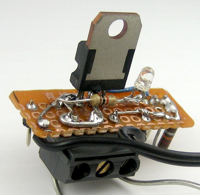 Anyway, I’m surprised with how pleased I am with this little guy. The fact that I can just throw it on an Arduino, and that I didn’t even have to make up a PCB means I’m not even sad it’s not Tiny85-based. The fact that it’s completely junk box parts makes me smile, too. This little bit of perfboard’s a winner!
Update 6/2/14: Here are the results of a current calibration on the bench (all in mA):
Actual 20 50 100 200 300 400 500 600 750 1000 2000 Reported1445 96 197 308 420 545 675 840 12001700Corrected 55 100 189 288 387 498 612 739 1015
Between those observations and the datasheet, it looks like at Vgs of say 4.8V we’re at the edge of linearity of Rds at an amp. The transistor got quite hot at 2A, so it looks like the practical upper limit is 1A. The current calibration constant is 1.67mV/count, so we’re at the ragged edge of digitization problems at say 20 mA. Let’s say a practical lower limit is 50 mA (and rocky at that).
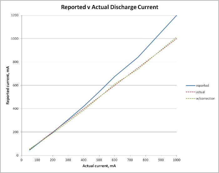 Taking the A/D count as Reported/1.67 and doing en embarrassing amount of manual cut and try in Excel, a final formula with corrections (A/D count=A): (A+10)*1.48-(IF(A>400)then((A-400)*0.2); else 0)) gives a pretty good fit over the range of interest. (Apologies for the Excel expression.) Red is ideal, green is corrected. Guess I better code that in (and test it again 🙁 ). Done.
Selection of a new MOSFET for building multiple units would like:
- Max continuous Ids > 2A, Vds > 5V (trivial)
- Rds(on) ~0.5 ohms (requires finding suitable part)
- Vgs of 4.5V fully saturates at 2A (requires finding suitable part)
OK, now I’m pretty comfortable with the current calibration, know the device limits and what next steps might be. I’m still really pleased with this little guy. And it’s done!
Update 11/12/17: This device was just pressed into service again (in a capacity it wasn’t designed for), after a fair struggle trying to figure out how to do a discharge test on a BWD sump battery. Its existence emerged only slowly out of foggy forgetfulness. I was very glad for these notes, first to remind me of the device’s existence, and then for enough detail to put it back to work in a new Rube Goldberg configuration. Details here. <link to not-yet-written post>
Having a newly updated Tiny84 datalogger, and using the big current sink instead of the external resistor usually used with this discharger, all I needed from this was voltage monitoring to cut the test off at a reasonable voltage. I found the dongle with a 12V automotive relay from some other 12V discharge test, and thought I could use this one just to control the 150mA to that relay to provide the shutdown function.
Can I get away with 12V?
Looking first at the 3.3K/12K divider for voltage sensing, I was pleased to see that it would work as-is for a one line code change by just used the 5V analog reference rather than the 1.1V one. I didn’t care about the current monitoring part, as I planned to set that manually (to a fixed 3A) in the current sink. Ignoring it was a nearly very costly mistake.
Having the 12V relay’s path to ground switched by the MOSFET was fine, and the 150 mA coil current was easily within the MOSFET’s specs. But because of the current monitoring approach, the voltage on the drain – 12V when off – was directly connected to an analog input pin (A4) on the Arduino. That’s not fine at all.
But it was much worse than potentially blowing a $3 Arduino. (Hmm – I should check to see if that analog pin still works!) The 12V fed back thru the USB connector to my nice new laptop, crashing it so badly I had to pull the battery to get it to turn on again. (I was very sad and mad until I tried that, fearing that the laptop had been damaged beyond repair.)
Making it even worse, my first thought was that it was a ground problem through the laptop’s power supply. (In hindsight, it’s probably isolated, though I really should check that out.) I’d needed to do the additional very non-standard thing of reversing +/- connections to the relay dongle, as it was wired to need +12 to the coil, whose other end was grounded. So after the first crash I pulled the laptop’s power supply and ran – obviously completely isolated – on battery. It crashed the PC hard again. The second time I got it running again still sitting on the floor in the power tool room by pulling the battery. Much shorter panic duration, but still very unhappy.
Thankfully, looking at the schematic again provided the insight that the 12V was directly connected to an Arduino pin (when the MOSFET was off). Using some jumper wires to connect this mini shield to the Arduino – without the current sense pin – allowed it to work as needed.
The takeaways are: 1) Don’t use this device for > 5V without somehow disconnecting the current sense pin; and 2) Don’t be sloppy cobbling things together to use higher voltages than they were originally designed for!