
 The big battery discharger works well (or so I thought) except for the case of testing single 1.xV cells. It just doesn’t work – reporting 0V often. There’s even a comment in the code dated 2/15/11 (right under the V1.3 update comments) that it doesn’t work with 1.5V cells. The comment was that the A/D returned 0 counts, and that it worked with 2 or more cells, and that I hadn’t looked for the threshold.
I had a bunch of NiMH cells I wanted to test and had forgotten about this problem. After going thru 3 battery holders, I started to make better observations, and rediscovered this problem. There are various debug prints commented out in the code, so it looked like it wouldn’t be too hard to figure out what was going on. (Wrong.)
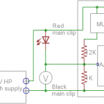
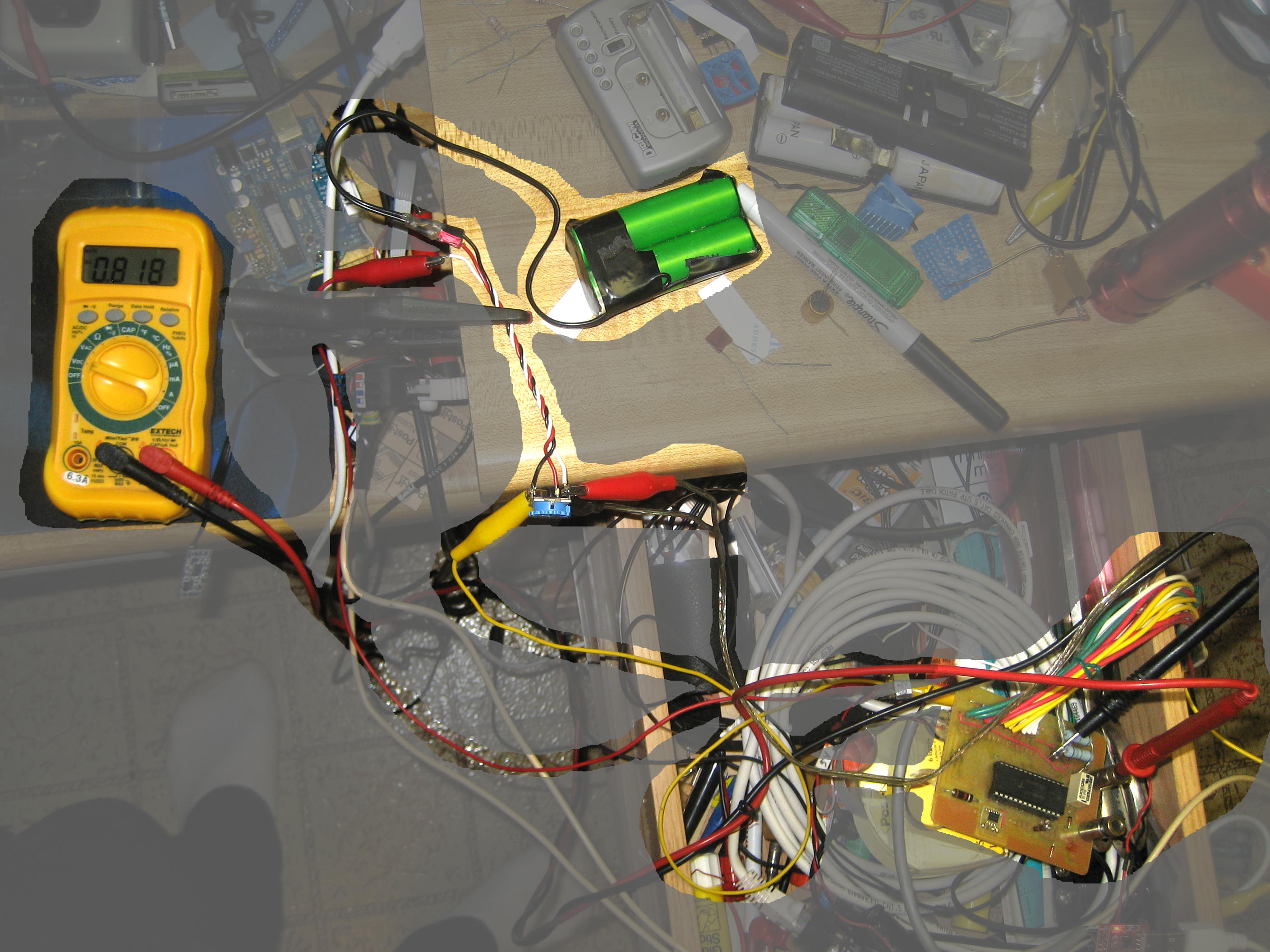 To get a handle on what voltage the problem happened at, I hooked a 2.5K pot across my good bench Li-ion battery for a stable adjustable voltage source. I put a good DVM across the main discharge leads (clear zipcord, R/B clips). The discharger code displays the voltage across the main leads while waiting for a CR to start the test. That should be a good test setup.
With the pot in the middle, the voltage on the DVM bounced all over the place – by several tenths of of volt. After a bunch of head scratching and other test configurations – including using the (AC) bench scope while powering the Arduino with the 1xAA 5V supply, I’m fairly confident in the following observations:
- There is a substantial – tenths of a volt or maybe much more – noise signal on the main discharge leads. I think I saw it as a more or less a symmetrical sawtooth.
- As I watched the “waiting” output voltage indication and played with the pot, there seemed to be a threshold around 2.1V. I’d occasionally see values in the range 0<V<2.1, but never stable. But that 2.1V indication was NOT at a pot slider value of 2.1V! There’s something VERY wonky about the voltage indications at low values. A few points: (Actual=pot set with leads disconnected, Reported = leads connected)
Actual V    0.06  0.11  0.65  1.0   1.4   1.5   4.0
Reported V  2.1   2.5   3.5   3.6   3.75  3.75  3.98
- With the pot set for 1.40V (measured with the discharger leads disconnected), with leads connected, the DVM bounced between 1.41 and 1.82 (watching for a minute or so).
- Hmm – that’s not consistent with the misbehavior: With a AA NiMH cell fairly fresh off the charger and measuring 1.38V, when I connected the main leads to it, the reported voltage dropped instantly and consistently to 0. With the leads floating, they showed ~4.1V. The source impedance of whatever’s on those main leads is very unclear.
- Scary question: Does this mean all the tests I’ve done for the past few years (on higher voltage batteries) have produced inaccurate results?
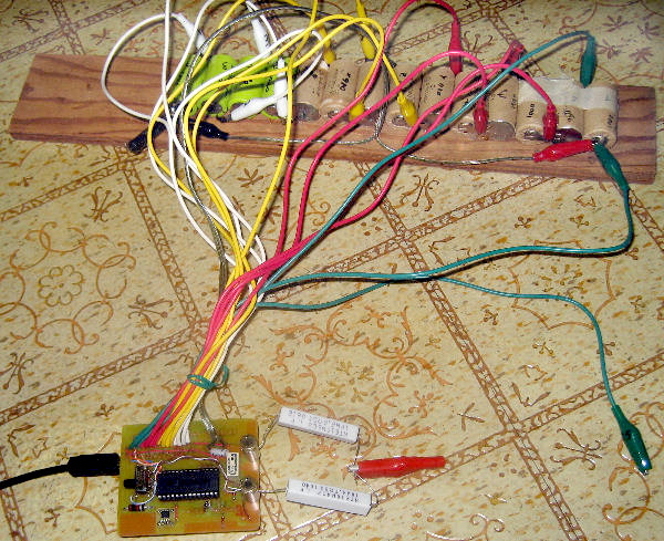
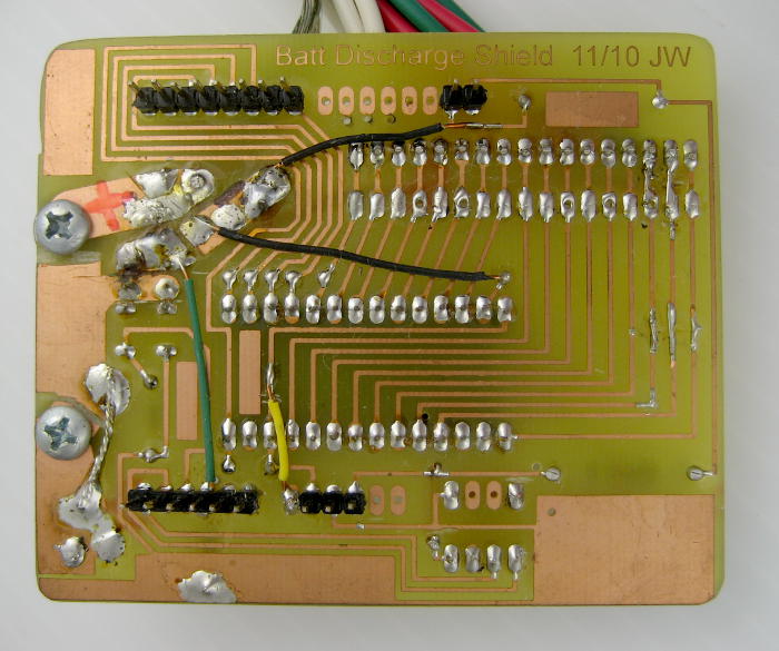
 For reference, here’s the board as it has been in service for the past couple of years. From what I can see/reverse engineer, the voltage out of the mux (from whichever input lead) goes thru a 12K/1K voltage divider (0.077 of orig) to Arduino A/D input A0 which is referenced to an external (on the discharger shield) 1.88V zener (sourced from 5V in from the USB/serial connection). That would give a theoretical max voltage of 24.4V for 1024 A/D counts. (Reasonable for nominal 18V Nicads, which were the original max target.)
- Continuing the theory, that would give a formula of (A/D counts) * (24.4/1024=.024) to get actual voltage. The code has a comment with that as the “expected” value and a #define of 0.0263 as the working calibration constant. For a 1 V input that would give around 38 counts on the A/D. Not a lot, but unless the A/D isn’t working well, it shouldn’t give any weird threshold effects.
I’ve spent way more time than I should on what I thought would be a fairly quick fix, and am grudgingly pulling the plug for now.
Next steps
 Put a bench supply on the 1K/12K junction and watch the indicated “waiting” voltage compared to actual. Yeah, I’m driving one side of the mux with that, but it’s thru 12K. Hmm – seems to me the specs of the mux chip say no inputs > some V+ voltage. I think that means I need to put at least as high voltage on the main discharge pins (which go to that V+ on the mux) as I’ll put on the mentioned test point. (That jives with a vague recollection of strong requirement that the outer ends of a battery MUST be connected before any of the per-cell leads.) Maybe a red LED to make that V+ about 1.7V higher than the test point? That ought to do it. Heck, even a Schottky should do it. Next step after that depends on what we see with this (if I ever get time to do it). But at least these notes will help me remember what I saw today.

There was a lot of daydream level consideration given to making up an even more “appliance” discharger, maybe for just one cell, probably with a Tiny85. By using a 1:1 voltage divider with 1% resistors (maybe 4.7K?) and the internal 2.56V band gap voltage reference and 5V power from the fake FTDI cable, it should handle a fresh 4.2V lithium cell and give good resolution. I even ordered some IRLB8721 MOSFETs with ~20milliohm RDS(on) for the discharge switch. (Thanks to Adafruit for choosing that part!) They’ll handle several amps, so keeping the external load resistor approach, it would handle most everything I’d be likely to throw at it. If I just had time to build it…
A little later: Oops – on 328P it’s a 1.1V reference. Rats.
Pingback: Quickie 1-cell discharger | Jim's Projects