I’d like to get a little more familiar with the time/temperature behavior of the hot plate reflow setup before I try any more real boards, so I need a recording thermometer to do some testing. I have some shiny new thermocouple wire and found a MAX 6675 K-type thermocouple interface IC (with reference junction temperature correction) that talks SPI for $2.50 and free shipping on Ebay. Ultimately I’d like to use that read only 8 pin SOIC IC in a temperature controller, but in the short term I just need something so I can read it from an Arduino.
And bless the Arduino community’s heart, sure enough there’s a library already done to read that chip. It provides (in addition to the constructor) one function: read_temp(). You tell it what pins the chip is connected to and it returns a float with the temp.
I laid out a minimal breakout board with just the IC, screw terminals for the probe, and a 2×3 header to match the ICSP header on my Duemilanove. I’d been underwhelmed by that connector initially, but have since used it to reburn the bootloader, and now as a quick and dirty I/O connector. It has Vcc, Gnd, and 3 digital I/O bits available – ideal for this application or various other mini-shields. (I’ve used the same connector on a Tiny4313 in a similar fashion.) And when the time comes to build a controller, I’ll unsolder the female header, solder in some wires, and connect it to the new controller board. (Hmm – I suppose I should have enough confidence in my SMT rework skills by now that I’d be willing to remove the chip from this first breakout board and move it to a properly laid out controller board. We’ll see.)
I found a bit of board material in the scrap pile just the right size for this little breakout – no cutting required. My etch bath is currently very busy dissolving more copper to increase its volume, but it should be available to etch this board very soon.
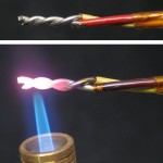 The thermocouple wire is quite heavy – 0.030″, 20-21 ga. The outer insulation is clear dark orange – quite reminiscent of the Kapton tape used in the hot end of the Makerbot. I stripped and twisted some and tried to weld it with a little butane Portasol torch. No luck. It got pretty bright red, but didn’t melt. The flame temps of butane and propane are almost identical, so even a larger propane torch shouldn’t do much better. <testing…> Nope, no
 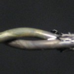 difference. And then I tried with my MAPP torch cranked all the way up – no joy there, either. It got bright yellow and did discolor the insulation a little more, though. Now I’m not quite sure what to do. I guess there’s the battery tab welder.
Hmm – or silver solder. Since the law of intermediate metals says it doesn’t really matter what other metals are there as long as they’re at the same temperature, I think that shouldn’t hurt accuracy too much. I fluxed the twisted ends with my usual brazing flux and tried to silver solder them in a propane torch flame. While the silver solder melted easily, it didn’t even begin to wet the metals. (A drop of the molten solder did, however, burn a hole in my laminate-topped bench. Normal solder – which I routinely fling off the end of a newly tinned iron tip onto that surface – flicks off with a finger nail without a trace.)
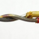 I cut off those old abused ends and started with fresh wire, twisted and fluxed. The solder wet the metals immediately this time. I have a junction! Now for the board.
The etch bath is still at ~4 g/l Cu+1, so it’s not finished regenerating after all the new copper, but it should work. It took a little over 30 minutes to etch the little board (usual time for larger boards with fully regenerated etchant is ~20 mins), but it came out fine. I used the still uncalibrated reflow hot plate to solder 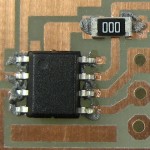
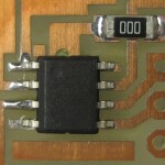 the one chip and one zero ohm jumper on the board, using the wait-’til-it’s-shiny-and-then-take-it-off technique. The solder paste was again a nuisance to try to apply smoothly. Here’s the parts squished into the paste, and how it looked after reflow:
While it looks like the leads on the right 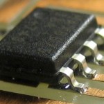 side aren’t soldered at all, there really was solder up behind the leads. Either the solder paste or the chip was just not well located.
 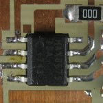 There was a similar problem with the first test – I’ll have to watch that. Just to make sure, I hit both sides with solder wick. Interestingly, the wick soaked up some extra solder from the left side and deposited some on the right side. So you can probably solder an SMT part by just fluxing its leads and heating up some solder-laden wick on the leads and pads.
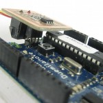
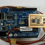 I dropped the MAX6675 lib in the libraries directory of my Arduino 0023 installation (I’m still not comfortable with 1.0), connected the thermocouple, plugged the board onto the ICSP header and brought up the example that came with the lib. Since it doesn’t use the usual SPI facilities, you have to tell it which pins you have chip select, clock, and data connected to. I fired it up, and it worked – reporting the temp each second! The only bad news is that I misspelled the name of the chip on the board. Boo.
The reported temp went up when I held the junction in my fingers, and down when I wet it with alcohol and blew on it. Since the chip has an onboard temperature sensor to correct for the unintended but unavoidable reference junction (making the assumption that it’s at the same temp as the chip) I put my finger on the chip and could see the reported temperature change. As simple calibration checks, I got out the yellow multimeter with a TC probe, put some crushed ice and water in a glass, swirled it around a bunch and put both probes in. Both registered about the same – 35 or 36F. (WTH!!??) I tried it with a cup of recently boiling water and they were farther apart – maybe 190 v 201F. As a double check, I dug out an old commercial TC themometer I’d forgotten about ’til now and put all 3 probes into the same hot water. The commercial one said 174, the multimeter 172, and my board said 178. Probably close enough for government work.
Now for what this was all leading up to: characterizing the hot plate. I hacked the example a little to put out comma separated values of time (in sec) and temp, so it would be easy to import. OK – the TC is in the well I drilled into the aluminum plate, the plate’s on the burner, and I’ve restarted the serial port capture so time 0 is when it starts. Power on.
First scary observation: The temp readings are VERY noisy – bouncing by 30 degrees over the course of a few seconds! When it hit ~212F I flicked a few drops of water on the plate. They skittered around as little balls riding on a layer of steam, indicating the temp at the surface of the plate was considerably above 212F.
I think target peak temp is ~220C, or 428F. As soon as it hit 428F (using the peaks) I shut power off.
Second scary observation: When I turned power off the reported temp jumped (in one reading) from 377F to 845F! It kept climbing for almost a minute, peaking around 872F. Was that real? I put the small junction of the commercial meter into a few of the holes in the plate. I didn’t see 870, but did see maybe 840. Yes, it really was that hot. For reference, the thermostat control clicked off after rotating only a very small amount as I turned it off. (It had been turned up all the way.) The good news is that the wild swings in the reported temperature (which peaked at a delta of 70F) were gone.
When the reported temp dropped to around 210F I again tossed a few drops of water on the plate. This time they evaporated in a few seconds (but didn’t boil). Here’s what it looked like:
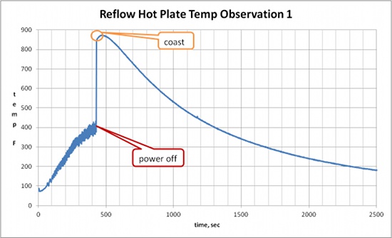 OK, after I turned the power off, behavior was just about as expected (though a lot hotter!), including initial coast up to temp peak and a nice exponential cool down. But what the heck is going on with readings while power is on?
The probe junction – which is connected directly to the chip, which is connected directly to the Arduino and through the USB connection to the computer – is certainly in electrical contact with the plate. Is there AC leakage through the burner coil? I’d expect the coil to be insulated (and the plug is 2 prongs, typical in double insulated tools), but maybe there’s leakage or capacitive coupling or something. Maybe I should ground the plate. Or at least look at the voltage between the plate and PC ground at the Arduino.
I guess the next run should be with a laptop running on battery and completely isolated from the AC line. Or run the Arduino from a battery and record the data. The 1 K of EEPROM would give us 1000 sec – enough to cover the time of interest. But it’s pretty essential that this gets resolved!
Trying the laptop is easier than writing to EEPROM, so I did that. (After upgrading from 0015 to 0023, copying the sketch and library over and finding the right USB serial port,) I fired it up, turning the power off when it hit ~428F. First, the thermostat control clicked off at a much more reasonable place somewhere between Low and Med as I turned it off. Second, the wild fluctuations in reported temp weren’t there. Third, the indicated temperature didn’t do wild stuff when I turned the power off. Quite promising.
On the way down, I put a few drops of water on the plate when it read ~320F. The water boiled off immediately, dancing around a little. When I did it again at ~220F, the drops stayed put, but bubbles were visible inside as they evaporated. At 200F, no bubbles. Those sound about right.
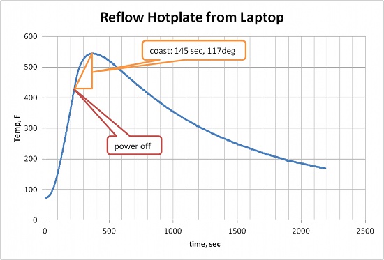 That’s much better. So the thermocouple interface board works, though I have to watch out for some sort of common ground problems. I guess I can live with that.

Pingback: Reflow hot plate calibration | Jim's Projects
Jim, the twisted junction you show is a terrible example of a thermocouple junction. You aren’t actually measuring the temperature at the tip where the soldier is, but instead the indicated temperature will be that further back, where the wires first touch. That is often why diagrams of thermocouples clearly show both wires staying FAR from eachother and then joining at the tip only, because any contact creates the junction, not just the final point of contact.
Dear Dude,
Of course you’re absolutely right that the “junction” is where the dissimilar metals first touch. But since this was made to sense the ambient temperature in a hole drilled 2 inches into an aluminum plate, I suspect the temperature gradient between the soldered tip and where the wires might first touch (subject to oxidation and mechanical stresses) is too small to matter.
But thanks for pointing it out for others who might read this. And I’ll solder closer to the insulation and clip off the end on the next one I make. 🙂