While the first few reflow attempts using the “turn it on, wait ’til the solder is shiny, take the board off” approach have more or less worked, it would be nice to see if we can come closer to a proper time/temp reflow profile without too much trouble. (Or at least know how far off from ideal we were.)
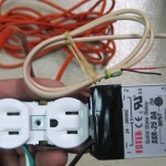 I assumed the hot plate was able to heat up considerably faster than the desired profile, so I hooked up a solid state relay I could turn on and off with an Arduino to control power to the hot plate. (Yeah, it should be in a box. But this is just for a quick test or 2.)
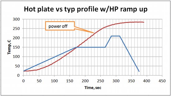
The first step is to see how that completely simplistic approach compares to a real profile. Here’s the ramp-up part of what the thermocouple interface measured, along with a sort of typical profile:
 Very interesting. The raw hot plate hits pretty close to a couple of the profile points. And it never ramps up faster than the profile, so the AC controller isn’t really needed. Guess I should have believed the bit about “The first step…”.
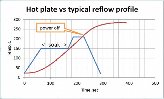
OK – the rate of initial ramp up to the soak plateau isn’t too critical, and the 2C/sec rate shown is sort of an upper limit. Using “whatever the hot plate will do” as the ramp up rate, a more appropriate picture would move the the profile line starting at the beginning of the soak phase:
We’re really shorting the soak region, and we can’t make the sharp spike up to reflow.  What if we at least flatten out the curve some by turning power off at – I dunno – maybe 100C? and turning it back on maybe 30 sec later? I guess I can make use of that AC controller after all. OK, here’s the logic:
– power on ’til temp>=100C
– power off for 30 sec
– power on ’til temp>=200C
– power off forever
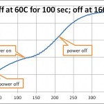 Oops – can barely see the “soak” time – let’s tweak some more:
– power on ’til 60C; off 100 sec; on ’til 160C; off forever
(I was impatient and that one started at almost soak temp so you can’t see the initial ramp up.) Rats. It looks like the frequency response is way too low to shape the curve much. The main culprit is probably the thermal mass of the aluminum plate, but I really want the plate to provide uniform heating of the PCBs. I suppose I could just use a smaller, thinner plate. The well for the TC would be a lot harder on a piece of 1/8″ aluminum…
If I put a fan on it, the “coast” time would be less, sharpening the knee at soak start, but the burner would have to work harder to heat it all up, so the rate of temp increase would also go down. Ugh. I suppose if we power-controlled the fan so it was only on when power to the burner was off… Yeah, it wouldn’t take any extra parts or pins (besides the second solid state relay) if I just connected the fan relay between the current relay drive pin and +5 instead of gnd, thus inverting the logic. Ugh.
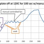
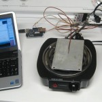 OK, let’s try 2 things: smaller, thinner aluminum plate (3.75 x 5.5 x 0.05″) and a fan when heater power is off. Hmm – big difference. I manually controlled the fan (several cycles) to keep temp about even during soak phase. The shape looks a lot more like what we want. Of course the TC was on top of the plate and directly in the fan breeze, so its temp was probably more strongly affected by the fan than the plate was.
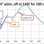 Here’s the 1/4″ plate but with the fan. Again manual fan control, but I turned it on just at start of soak and only turned it off several seconds before soak ended. The burner can only raise this one’s temp a deg/sec, while the thin plate can go 2 deg/sec. But we still see something much more like the desired profile shape. The down side is that a fan anywhere near the top of the plate will cool the tall components on the PCB the most, creating vertical thermal gradients – exactly what the soak phase is designed to avoid! I suppose if I raised the whole thing up, cut a big hole in the bottom for a muffin fan and cut out the drip pan under the burner so air could blow UP on the burner and bottom of the plate, that would avoid cooling the PCB. And added a second solid state relay and some more logic to optimize its on/off times…
So it looks like it would be possible to implement a soak phase. But the real question is: How much trouble is it worth to get a more proper temperature profile? I don’t know. 🙁

