Dan, Jim (from FSI) and I did a first round of surface mount reflow soldering tests on my new hot plate at the space Tuesday evening. Results were excellent – even better than I’d expected.
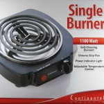 I chose a hot plate over an electric skillet because it felt like the sides of the skillet would get in the way and provide extra opportunities for me to burn myself. The hot plate I got was $12.50 with free Super Saver shipping from Amazon. Based on reviews there, it came much more highly recommended than some similar hot plates. The 1100W single coil type burner has a common rotary mechanical thermostat for temperature control. It was used for little more than on/off in these initial tests, though it will probably be useful as the technique is refined. The burner provided more than enough heat for reflowing.
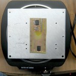 To spread the heat more uniformly, I put a piece of scrap 1/4″ aluminum plate on top of the burner. Here’s one of the test PCBs on the aluminum on the burner.
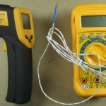 Temperature monitoring was by way of two devices, both yellow. I succeeded in finding the never-used thermocouple probe that came with a multimeter I’d bought several years ago. I also took the hotplate project as an excuse to get a cheap IR thermometer (with laser sighting – oooh!). That one was $17.20 from Amazon, and was also used to put the order over the $25 minimum for Super Saver free shipping. A great deal! The IR thermometer is very useful for this application, if a little awkward because it’s hand held. The plan is to drill a 1/8″ hole as deep as I can sideways straight into one edge of the aluminum plate as a well for a thermocouple. I’ll use the one shown here for now, but might use another connected to a temperature display and controller some day. Or not.
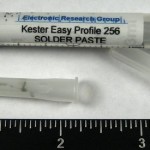 There was serious question around what to do for solder. I had a 0.5cc syringe of solder paste that’s been sitting in the fridge since 12/07. Shelf life is supposed to be 6 months or a year, but what the heck – it was worth a try. While it would be possible to make a mask and squeegee the paste on, the thought of all the additional steps to do that put that approach very low on the list. I’d seen demos of just squeezing a continuous bead of paste out across the pads for each side of an IC, and that seemed easy enough to give it a try.
My main hope was to generously tin the component pads by hand with conventional solder and remelt that with the component sitting on top of it at reflow time, avoiding all dependence on solder paste, its shelf life limitations, and application problems.

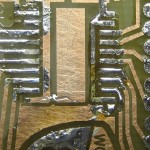 I happened to have a board with two identical layouts (latches for the Scrolling LED Display project), providing an ideal way to compare the two solder approaches, so that was the first board we did. Here’s one side with inexpertly applied solder paste and one with hand tinning. I was surprised that my hand tinning was as non-uniform as it was. (The tinning on the W88 logo was part of another test.)
I smeared a little paste flux (not to be confused with solder paste, which contains flux) on 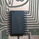 all the pins of the 2 latch chips and set them in place. The flux both provided the usual chemical cleaning and helped keep the chips in place. The latter was especially needed for the chip sitting on the lumpy tinned pads; it was probably not needed at all with the solder paste. I did remain sufficiently in possession of my wits that I got the Pin 1s in the right places. Here’s a pic of the fluxed chip squished down onto the solder paste. We put the board on the aluminum, fired up the burner, and started to watch the temperature.
It heated up pretty quickly, with the whole reflow cycle taking maybe 2 or 3 minutes. The first thing we observed was a little smoking, presumably from the flux. Then all of a sudden we noticed the solder was shiny – it worked! While I shut the power off right after the solder melted, the board started to discolor, and at Dan’s strong and very appropriate urging, we slid the board off the aluminum (and on to a convenient piece of green scrubby we’d used to clean the boards). I suspect the temperature of the aluminum was still going up at that point. I guess I should do some more formal testing to understand the characteristics of the plate’s temperature as a function of time and power to the burner.
(Hmm – I have a MAX6675 thermocouple interface IC that talks SPI/I2C (and some shiny new thermocouple wire). If I just made up a quickie breakout for it I could hook it up to an Arduino and make a recording thermometer, making the testing above much easier – especially after the first or second trial. I wonder where that should fall in the project priority list?)
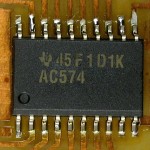
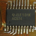 Here are the two chips after reflow. I figured the thick bits of tinning would flow around the pins, but that obviously didn’t happen much. I suspect all the pins are electrically connected to the pads, but I’ll add a little solder by hand before I put them into the LED display. The paste solder side (left) looks great! No bridges, almost everybody looks nicely wetted. I’m starting to be a believer in solder paste.
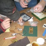 The second board we did was considerably more complex. Unfortunately I didn’t have quite all the parts, so I’ll have to finish up my hand, but we got most of the board done. Fortunately, we had a completed, functional version of the board we were working on as a model. Jim and Dan sorted thru the little bags of 1206 resistors to pull the ones we needed. (Something like 50 each of 20 different values for $13 or something from Ebay – a great
 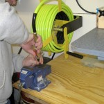 investment!) The syringe of solder paste came with 2 nozzles, and I used the smaller one on the first board. That seemed a little skimpy, so I used the larger one on the second board. Dan blew the paste out of the first nozzle with compressed air. (Many thanks for bringing that compressor and hose in, Dan!)
We took some videos of me applying the solder paste to the second board. My technique improved considerably by the end of the work. I’ll clean up the clips and post links here Real Soon Now.
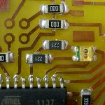
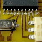 The finished board is discolored – presumably from not taking it off the burner as soon as we should have. But the soldering quality is excellent. Those resistors are considerably better than I can do by hand. The processor chip looks very good, too. One solder bridge, but that’s trivial to fix with some solder wick.
OK – now I’m convinced. Reflow with solder paste produces better results than I can do by hand – and probably takes less time, especially for more complex boards. This started out as an experiment to see if/how it would work, and gain a little insight in case I might ever actually need to use the technique at some unspecified time in the future. But now I think this will become my primary technique for SMT soldering for all but the simplest boards. Wow.
There are still questions about solder paste. What I have doesn’t stick very well during application. Maybe after 5 years it’s a little dried out. (I suspect the short shelf life quoted is based on industrial use with paste stencils. Viscosity and flow have to be tightly controlled for machines to apply the paste consistently. For hobbyist use where I’m watching each bead I lay, I can probably get away with stuff that would choke a machine.) Fortunately there are folks that sell small syringes of it on Ebay, so I’ll probably get some fresh stuff now.
I have a new way to solder!

Jim that’s really cool. I’d like to get to a point where I can do reflow like that but my recent attempts at toner transfer to copper clad have been… bad. Do you have a basic write-up on what you’re doing for that now? It looks like you’ve got really clean boards.
I read a long post about adapting a toaster over to do reflow. The first thing he did was to measure the thermal hysteresis of the oven, so he could compensate for it. Used a type k thermocouple and watched the temp as the oven heated – when it got close to solder temp turned off the power and noted carefully how many degrees it continued to climb. So you need to know what temp the solder melts, and then turn off the power early by that many degrees. Also supposed to have a gradual cool down over many minutes to minimize thermal stress in the soldered joints. That might not matter in a small board.
Jim,
Yeah, toaster ovens are the other common way to do reflow. Ted donated one to the space for that purpose, though no action on it yet.
I did successfully drill a 2″ deep hole into the edge of the aluminum for a thermocouple. (Let’s hear it for drill presses!) I’m trying to figure out how to make a quickie minimalist board for the MAX6675 so I can just hook it up to an Arduino for now to record time/temp behavior and later go on to use it with a dedicated processor (probably a Tiny4313) probably with an LCD display and a solid state relay for actual control. That same setup could be used (with slightly differently tweaked software) with the toaster oven.
I also need to watch with the IR thermometer to get a rough idea how fast the temp drops after I pull a board off to see if I should do something like putting the board on a much smaller piece of aluminum to add some thermal mass and sliding the pair off together on to some thermal insulator (like the scrubby) and possibly covering it so it cools more slowly. I’m not trying to hit the recommended thermal profile to the last deg/sec, but I’d like to be within an order of magnitude of it.
Dave,
Sorry no writeup. Sounds like I need to do the ‘how to make a PCB at home’ class again at W88!
I use positive photosensitized board material. I usually get this 1 0z copper stuff and use 1% NaOH mixed from dry pellets for developer. (I’m guessing you could use Drano.) I prepare artwork from board layouts done in Eagle by printing on transparency material with a cheap inkjet printer. Took a while to get the best settings. I cut a piece of board the right size with a hacksaw while clamping the material between 2 wood blocks with rubber waffle material on the sensitized side so as not to risk damaging the surface. I expose for 5 minutes 2″ below a 13W spiral CFL blacklight bulb with a piece of glass on top to hold the artwork against the board. I reverse the artwork so the ink side is next to the board for best resolution. Develop in maybe 20ml of fresh developer until it looks perfect – maybe 30 sec – and rinse. Then etch, drill, solder, troubleshoot, yada yada.
Oops – yeah I guess I did write it up somewhere 🙂
Pingback: RF starter’s gun | Jim's Projects