
Well that was embarrassing. I thought I could knock out a quick mini-shield for an Arduino Mega to use as a programmer for Tiny85s (or most any other AVR chip). I did, and it works, but only after two iterations of repairs due to dumb. And it’s still not close to ready for prime time. (But see update at end.)
 The shield I made for pre-Megas was small and simple. (The one at the right is the simplest – no LEDs. Current ‘production’ versions have the heartbeat LED; my personal “good” one has error and comms LEDs as well, but it’s the only one I made that way.) The shield picks up the SPI connections (10-13) (plus one or more of the pin 7-9 LED lines) on one side and spans over to pick up power and ground on the other. Convenient pin placements, and I took advantage of it.
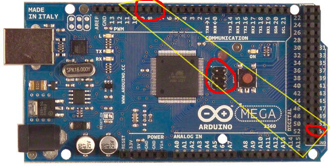
The Mega’s pinout is the problem. The ArduinoISP sketch apparently uses the actual SPI pins on the host processor to talk to the target. Those are brought out on (Arduino) pins 50-53 – on that long new header across the end of the board. Very inconvenient for a mini-shield.
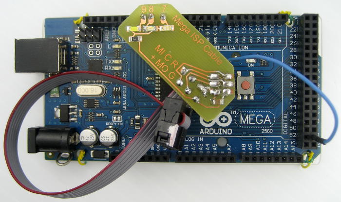 BUT – because SPI is also used for programming the chip, the lines are also brought out on the 6 pin ICSP header. (Well, most of them.) That’s much closer to the LED pins (7-9). And the ICSP header has the power and ground I need, too! If I oriented the shield diagonally, I could get everything I needed (or so I thought) on a shield about the same size as the ones for pre-Megas. I laid one out (with thanks to SparkFun for having an Eagle footprint for the Mega board!) That it’s crooked-wise sort of adds a little charm.
So I made one up and tried it out. Couldn’t load Arduino ISP. Right – it’s got the cap to keep the programmer from resetting when new code is sent down. Took the shield off, programmed ArduinoISP fine. Put the shield back on and connected the cable to the ICSP header on a Duemilanove. (I didn’t want to load code to it – but if I could confirm the device signature that would mean I could talk to it.) Fired up avrdude and got the command line params right in just a few tries. But it didn’t work – and just gave some unintelligible error message.
Dumb # 1
I looked at the ArduinoISP code, and slowly the line “#define RESET SS” sunk in: I didn’t connect RESET on the cable to the target to the host pin (53/SS) they’re using to control it! I’d gotten so delighted with using the ICSP header on the Mega host that I connected the target’s RESET to the host’s! Well that’s just wrong.
Took the shield back to the bench to hack the correction in. I was going to have to add a darn flying lead to get out to pin 53 (SS, the pin ArduinoISP uses to control the target RESET). That would never do for the production version, but at least I can get this one running. To disconnect the target RESET from the host’s, I ground the pin from the female header to the host’s RESET pin off below board level, and patched the new pin 53 wire to the wire to the target‘s RESET, and made sure it was also connected to the 10uF cap. Back to try again.
Dumb # 2
Still didn’t work. Eventually it came to me: That 10uF cap goes to the host‘s RESET pin, not to the target’s where I’d hacked it to! And more bad news: the host’s RESET pin was the connection I’d ground off to below board level. No way was I going to be able to connect to it now.
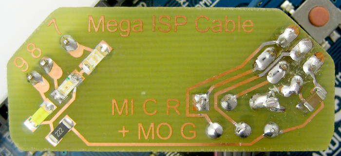 So I removed the 6 pin female header, cleaned out the holes and soldered a new 6 pin female in – this time with all the pins accessible. A little trace cutting and finessing with bits of wire and I had everything connected to where it should be connected. And this time it actually worked!
I hadn’t been sure which programmer to tell avrdude to use. It seems to be happy with arduino, avrisp, stk500, stk500v1, stk500v2. So now it could read the device signature and even dump some flash.
Now what?
OK, now I know how to make it work. But I can’t do it with a “mini” shield. And I really don’t want a flying wire. Can I just use a different pin to control the target’s RESET? I tried pin 2 (after also adding a pinMode(2, OUTPUT)). Nope. But the prospect of having to run a hacked ArduinoISP sketch was pretty bad anyway.
I can get all the SPI pins (50-53) plus power and ground from that new long header across the end of the Mega. But then I don’t have the LEDs. Yeah, there are lots of pins on that header that I could re-assign the LEDs to. But then we’re back to a hacked ArduinoISP sketch. The minimalist size of a shield using only that long new header is very appealing, and very much in the spirit of the original mini-shield. But I really like having at least the heartbeat LED. I suppose I could put the LED on, connected to some other pin, and say you can get it to work if you change the one line “#define LED_HB 9” in the sketch, but that it will still work (without the LED) if you don’t. And most people don’t even know about the LEDs in ArduinoISP, so not having them isn’t really a loss. (But I know about them 🙁 .)
Update 1/29/14: I’d almost settled (with all the negative connotations) for using only the new header on the end of the Mega (with remapped LEDs). With something like “#if defined __AVR_ATmega2560__” I could even toggle the LED pin defs so I’d have an ArduinoISP sketch that would work with either mini-shield. But when I started to lay it out, I realized that doesn’t give me access to the host’s RESET line to connect my auto-restart-defeat cap! Bummer – that’s a non-starter.
Or I could just make a huge (by my “mini” shield standards) say triangular shield across the whole new header and going up to pins 7, 8, 9 for the LEDs. But I’ve lost the “mini” part. (Oops – that doesn’t give me the host’s RESET. Won’t work.)
 I guess it might be possible to do a long, skinny shield catching 7, 8, 9 for the LEDs, the 6 pins on the ICSP header, and then going out to pick up pin 53. But they don’t really line up very well, and that’s kind of weird anyway.
Extremely minimalist (no LEDs, no PCB!) would be a piece of ribbon cable with two 2×3 female header ends. But the RESET pin wire from the target end would be a couple inches longer and not crimped into the connector at the host end. Instead, it would just have a 0.025″ pin attached. Plug that into pin 53 on a Mega or pin 10 (SS) on an old 328-based Arduino and it should work. Rats: That doesn’t give me a way to defeat auto-reset either. OK – a small PCB at the host end would do it. But more work and still no LEDs 🙁 .
Maybe I should just do the weird diagonal one (wired correctly, of course!) and put up with the flying lead.
Ugh.
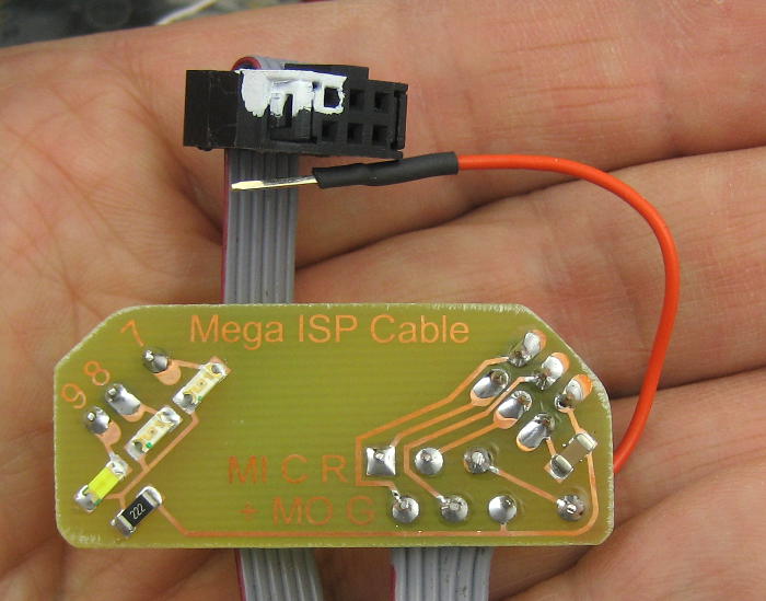 More update 1/29/14: The lesser of evils (at the moment) is the flying lead and the diagonal PCB. Here’s the first one. The PCB is corrected, and there’s a nice pad for the flying lead. I need to make a nice tag/label for the flying lead that says “Pin 53”. That whiteout Pin 1 mark on the female header is pretty ugly. But it’s effective, and I finally made the cable come out the sensible way to plug into the ICSP header on an Arduino in case you need to re-burn a bootloader.