
(This is one of a pair of unrelated Tiny projects that seem to be going on in parallel. I don’t think I could have chosen two more confusable projects if I’d tried.)
From time to time I’ve wished I had a dedicated data logger. I limped by with various lash-ups, including using DTR on the serial port of a Windows 95 laptop (they had actual serial ports back then!) to sense current to the ejector pump over weeks to spot a leaky toilet.
The desire to log daily output from a small solar panel I hope to use in a tree-mounted security camera almost got me to make a logger, but it was the need to investigate the wind at the top of the Workshop 88 sign post (to see if a wind turbine there would work for a light for the sign) that finally tipped the scales.
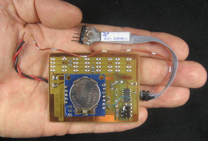 I laid out a Tiny84-based logger. Of course it has a standard 6 pin ICSP programming header and a couple of input pins brought out. But for something that may be running for days or weeks at a time, it’s good to know what time it is. The “Tiny RTC” module with its DS1307 clock chip takes most of the board space. It’s held on 1/4″ off the board with stiff wires in a few of its various I/O pin positions. Looks funny but it should work.
RTC Module
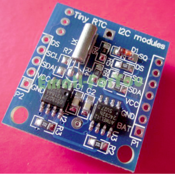 The RTC module had been sitting around since long before I’d gotten around to making the logger. I tacked a couple of wires on for the I2C interface, found the “RealTimeClockDS1307” lib for Arduino, verified that I could talk to the module and that it worked, so I anticipated no problems. Wrong.
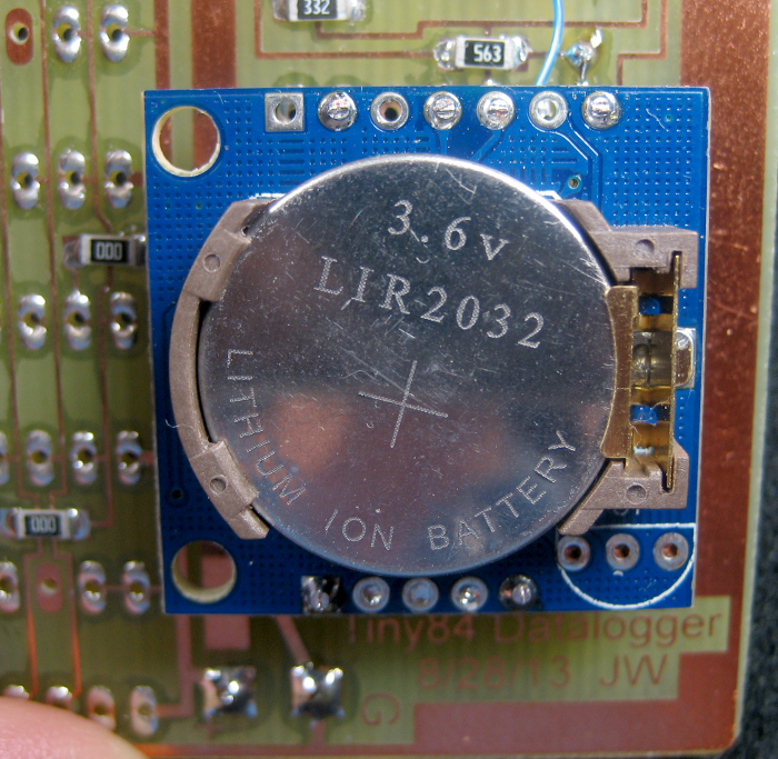 One interesting feature – that I didn’t expect on a Chinese cheapie – is the battery. Yeah, it’s a 2032, but not the usual kind: It’s a Li-ion rechargeable! The board has a crude charging circuit – a diode and 200 ohms to the 5V power rail. The sheet says it should run for a year on a full charge. Interesting.
Also interesting is that the battery is only to keep the chip running – not to allow any I/O. It needs 5V for that. I knew that by the time I laid out the board, so it gets power OK. What I didn’t anticipate is that 5V is a problem: To run a long time unattended, a couple of 18650 Li-ion cells is the battery of choice. But the module won’t run on that, so I can’t actually read the time from it – which was why it was there in the first place! Yeah, yeah, I could use a boost converter. But the next cheap RTC module I get will have a DS3231 – which will run on 3.3V – for a couple bucks more.
The DS1307 can provide a 1 Hz square wave output. I’ll try to use that on the ’84’s INT0 to at least get an accurate 1 sec interrupt. Of course even that output doesn’t really work without 5V to the module. Fortunately, part of the square wave output circuitry seems to be an open collector transistor to ground. With a 47K pullup, it seems to produce a useable logic level. Completely out of spec, but it might work.
The nice DS1307 lib I found for Arduino provides lots of features – including interactively setting the time and date. When I hooked it up initially, I set those, and thought I was done. Unfortunately, while rapping the module on the bench to knock solder out of the holes, the battery popped out. It didn’t occur to me until later that since the Tiny84’s TinyDebug Serial doesn’t provide any input, setting the clock now that it was soldered to the logger board could be a challenge! Not resolved yet. (It is now – see update.)
Oops – you wanted a debug output with that?
While I did bring a couple of ’84 input pins out to pads, I failed to consider that I’d need some debug output. The Tiny cores now contain the very nice (meaning small) output-only TinyDebug Serial lib – aliased in as Serial for chips like the 84/85 with no UART so it’s transparent! 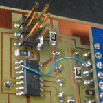 Unfortunately, the pin it uses is hard coded to PB0 (pin 2), and of course I hadn’t brought that one out. Fortunately there were a couple of unused pads under the RTC module, so I tacked a bit of #30 wire wrap wire over to one of those pads and ran an external wire from it (the brown/white one). If I were motivated, I’d replace the ribbon cable that brings out the I/O pins with another just 1 wire wider, but what I hacked in works. Of course it’s output only, so the nice clock-set stuff in the DS1307 lib won’t work, but I can probably get around that.
I2C/TWI on a Tiny
When I tried to load the DS1307 sketch on the Tiny, it wouldn’t compile. That was the first of lots of learning opportunities about “wire” libs for Tiny. The DS1307 talks I2C, which for real Arduinos is handled by the “Wire” library. The DS1307 lib I found hides that, and makes calls to Wire internally. Unfortunately, whatever Wire-like lib there is in the Tiny core isn’t completely compatible with the original Wire.
(The AtMega series of processors have full hardware support in the chip for I2C – and the Wire lib is written to use that. The Tinys don’t have the same internal hardware, so Wire won’t work. Tiny chips do however have USI hardware support – which can do most of the work for I2C. So Wire replacement libs for Tiny are written for that hardware. At least one version is called USII2C – an ugly name, but meaningful if you understand some of what’s going on under the covers. Of course there are lots of Tinys, and they don’t all have identical hardware, so what works on one… Ugh.)
OK – so I found a TWI lib for Tiny. (Two Wire Interface is the workaround name for what is essentially I2C – but Philips is fussy about that name.) That still didn’t work, because the DS1307 lib I was using makes calls directly to Wire. I can probably hack up a new version of the 1307 lib with calls renamed for the TWI lib. Or just find some 1307 code with more accessible library calls.
Serial EEPROM
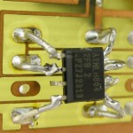
The plan for storage for this round of data logger was to use some 8 pin serial EEPROMs I’ve had sitting around for some time. Unfortunately, I misremembered their packaging: I thought they were ordinary 300 mil wide DIPs, and laid the board out for those. After I couldn’t find the chips in my DIP collection, I eventually figured out that they were in fact SOIC SMD parts.
I found the chips in the SMD collection, but while the pinout is the same, the footprint isn’t. I’m hoping with some fancy soldering and bending of wires in the DIP holes, I can connect the the SMD parts and support them in mid-air. On the plus side, that hovering-style mounting echos the mounting of the RTC module, so at least it will all look like it goes together. Or look equally dumb.
Update 8/21/14: I finally got around to trying to use the SOIC-8 AT24C512s (probably for a future datalogger with a 3V RTC). Unfortunately, the EEPROMs only have a house number, so I don’t know what voltage they run on. I figured the easiest way to talk to one to try it out would be to mount it up to this old logger. Then I can see how low a voltage it will work at. (The ~3.0V bottom range of a Li-ion would be nice.) That will also let me make sure I can talk to it with a Tiny84. (That last part turned out to be hard.)
 I followed the original air wire mounting plan. Thankfully, there was no mention of “pretty” in the requirement spec. From the Eagle layout, it looks like the bottom left EEPROM (right under the Tiny) I used is address zero.
I found an AT24C library that should talk to the EEPROMs, but it’s based on the Wire lib. Initial efforts to port it to use the TinyWireM lib that uses the USI hardware in the Tiny84 have been frustrating (read: unsuccessful). After running into the dreaded “relocation truncated to fit: R_AVR_13_PCREL against symbol `exit’” problem, at least I got it to compile and load by using E Reid’s Arduino 1.0.5 ERW version. Thanks Erwin! (I bought him a Pepsi.) But it still doesn’t work right. Now I get to figure out whether it’s something funny with a 24C512 (which I vaguely remember as an issue), or the board layout, or the chip, or the weird soldering…
Troubleshooting
I’m running a slightly modified version of the EEPROM test program (AT24c_cpp.pde – very similar to the lib name!) and getting Tiny Serial Debug output from the added brown/white wire to a TTL/RS232 board to a serial port on the PC. I see output, so that part works. (Latest – and working – version is AT24C_cppT2.)
I looked at the board layout, and SDA and SCL seem to be correct. Of course they also go to the RTC (and the ICSP header!). How about pullups? The RTC module shows 3.3K pullups on both lines, which should work for the DS1307, AT24C32 and all other devices on the I2C bus.
How about device addressing? Looks like all 2-wire serial EEPROMS use an 8 bit address like this: 1 0 1 0 0 A1 A0 R/W. Hmm – the RTC module has a 24C32 at address A1/A0=00. Since I chose the same address, those 2 will crash. Of course they should both behave the same, but that’s risky. Ah – but if the new 24C512 were just completely not working, the test program should at least work with the onboard 24C.
I soldered a couple of short wires to an unused serial EEPROM spot to bring out SDA/SCL and hooked it up to the USBeeSX logic analyzer. After some some struggles with the 2-wire serial decoder (SDA and SCL must both be high at the start of the window) I got it to decode the I2C bus going to the EEPROM. Powering the logger board from the ICSP was a bad idea – it messed with SDA/SCL (aka MOSI/SCK) enough that the EEPROM didn’t work (except once !?).
Bad hardware?
 Fearing that somehow the 24C32 on the RTC board was confusing things, I wanted to set the ‘512 to address 01. Murphy was right in there though: If left unconnected, the address pins default low, so I couldn’t just disconnect one. I had to actually tie A0 (pin 1) high. Fine – I can use the pin1 pad from the next (unpopulated) chip spot. I could talk to it, but it still didn’t work right.
Bad software?
The USBeeSX has a nice ‘pulse width’ cursor feature, and while looking around with that turned on, I discovered the hi clock pulses were only about 1μs, for a clock freq of ~500KHz. The default/conservative I2C clock frequency is 100KHz, so I went looking around. Down in USI_TWI_Master.h (the lib BELOW TinyWireM) there was a line #define SYS_CLK 1000.0 // [kHz] Default for ATtiny2313 .
I changed it to 8000 for my 8MHz Tiny, but it didn’t help. Then finally in USI_TWI_Master.cpp, I found a hard coded CPU speed (F_CPU) set for 1MHz. Changing that to 8MHz slowed the clock down to 100KHz. (Since F_CPU is also in boards.txt for this board, maybe bracketing that with #ifndef F_CPU/#endif might make it work automatically. Or just removing the #define?) But it still didn’t work right.
I gave up on the original AT24C lib and made a modified version specifically to run on TinyWireM. I eventually abandoned the library completely and went with some local functions that write directly to Wire (modified, of course to use TinyWireM). I stared at USBeeSX waveforms a lot, learned more than I wanted about the details of I2C hardware protocol and probably other stuff I’ve blocked out. Blew DAYS on what I figured would be a one-hour test.
The problem
I finally learned that at least this chip needs a 2ms delay between writes. It works for a while without the delay, but then fails. Failure is just NACKs on writes. I spotted those NACKs with the USBeeSX’s decoded display. I’d even tried putting a 1ms delay in (maybe a day before I got it working), but it needs at least 2ms. So close…
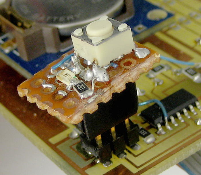 So now the write/readback test sketch works with this chip at addr 01. I’ve run a couple of cycles of writing/reading all 64KB successfully. Now I can actually do the lower voltage limit test I started out to do days ago! Needs a way to show success/failure without a terminal (since there isn’t one near the bench supply). Made up a nice reset button with an LED that plugs on to the ICSP header, added a little code to blink once if OK, twice if readback error. Test time!
Results!
Running 5 or 10 cycles of writing 600 consecutive bytes and reading them back, I saw no errors down to 2.5V. At 2.4V the test reported errors maybe 1/3 of the time. Now this is only a sample of one, and could have been the best one of the lot, but these results give me pretty good confidence in the chips I have at least down to the very bottom of a Li-ion cell’s life. I’ll probably run a series of tests writing and reading back all 256KB of the final 4-chip logger at reduced voltages, but now at least I think if I build it it will work.
Using the DS1307-based RTC
I guess I learned my lesson with the serial EEPROM when I gave up on libraries and just used local functions writing to TinyWireM. After the first couple of DS1307 libs (written to Wire) wouldn’t work, I gave up and used local funcs writing to TinyWireM. Probably saved a couple of days doing it that way.
It’s a real violation/disappointment from the standard Arduino approach of “Just go find a lib somebody has already written for your chip and use it!” But I guess that’s the price we pay for using $1 chips that aren’t really supported.
Anyway, I got what I needed: A one-time sketch that sets the RTC, turns it on, and turns on the Square Wave output at 1Hz. Year, month, date, hour, minute are all just hard coded and will need to be changed each time the sketch is run. But that shouldn’t be often if the LIR2032 actually runs the clock for a year.
I’ve verified that the 1Hz square wave is available even if the DS1307 isn’t getting sufficient power (like < 5V), and that it goes to INT0 (pin 5) on the Tiny84. (While I put a 47K pullup on my board, it looks like there’s already a 3.3K pullup on the RTC module!) I haven’t tried to write anything that uses that interrupt yet. I can also confirm that you can’t talk to the DS1307 via I2C with just a Li-ion cell for power – you really need 5V.
So with its 64K of EEPROM and working 1Hz square wave, (and working – but useless at 3.7V – real time clock) this first datalogger is hardware complete and (with some suitable code) could actually be used for something. Yeah, that EEPROM is pretty fragile. Hmm – I wonder if I should just pot it in hotmelt glue?
Next version
This should become a new post, but from things I’ve learned recently, here are some thoughts/requirements for the next (the “real”) datalogger:
- Tiny84 is fine – has lots of I/O
- MUST run on 3V (bottom end of Li-ion discharge curve) including RTC (DS3231)
- Use some of the nice new 0.1″ screw terminals I got recently
- How about some female header pins for a daughterboard for some feature not yet imagined?
- While the “standard” 0.1″ male pins would be an OK power-in connection, how about just putting a 2×3 female header on the battery leads that would plug directly into the ICSP header? (Or, I suppose, an adapter from a 2-pin 0.1″ male.)
- Be sure to bring the TinyDebugSerial pin out. Probably a pair of pins with out and gnd.
- Put a couple of LEDs on. Nice for poll indication, other stuff.
- Include a switch/jumper for Enable Logging. After you’ve got the data, you don’t want to start overwriting it while you load the data dump sketch! Maybe alternatively have a one-time ‘armed’ flag in EEPROM.