
I’ve been interested in (cheap) AC current measurement/sensing for a few years now. The first driver was wanting to add whole house energy usage to the home monitoring system. (I even 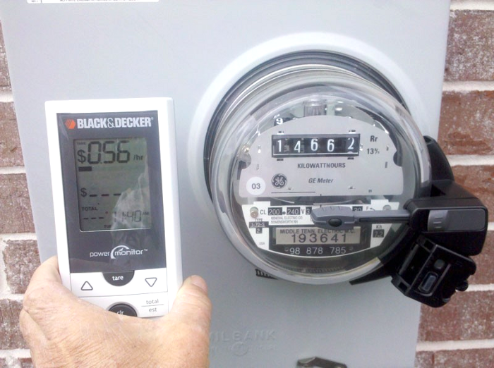 got a Black & Decker EM100B strap-on electric meter reader on some deal site, but haven’t gotten around to decoding the protocol from its RF receiver yet.) And I’d like the shop vacuum to turn on automatically when I fire up the belt sander, so sensing on/off would be good too. (Yeah, I know you can buy them. But what fun is that?) I did use a surplus toroid from the junk box for a current sensor on the sump pump power line so the monitoring system knows when that fires, but couldn’t find a cheap reliable source for those coils for other projects.
I read up some on current transformers, hoping to put some split-ring version on each of the 2 very fat service phases coming into the house main AC distribution panel. But while I found some openable cores, I’d have to wind those coils, too. Toroids are really about an ideal core for the sensing/measurement applications I was looking at. Update 1/24/18: A new “smart meter” installed a year or so ago includes an IR pulse per some unit of energy used that I hope to sense for quasi real-time power usage.
 I looked at the really cool toroid coil winding machines, but after I finally figured out how they work, it looked like they were too complex/precision to make for my infrequent uses.
The problem is threading the wire thru the closed loop of a toroid core. I devised a topological cheat, and made a first prototype. Then I tried the technique at W88 and Ti got some nice pics and videos of it, written up here. Anyway, I now have a working wound toroid.
Signal amplifier
The cool thing about toroids for AC current sensing is that by just threading the (insulated!) current-carrying wire thru the core, it becomes a one-turn primary of a transformer. (Loop it thru again and the output doubles.) As with most transformers, our secondary sensing winding is completely electrically isolated from the AC line.
Unfortunately, with the 200 turns I wound on my first prototype toroid, I only had a few tens of millivolts with 0.5A (60W light bulb) thru one turn of primary. Fortunately, since the output was going to a processor for logging, getting 5V to supply power to some electronics was no problem, so I could afford to add a small amplifier.
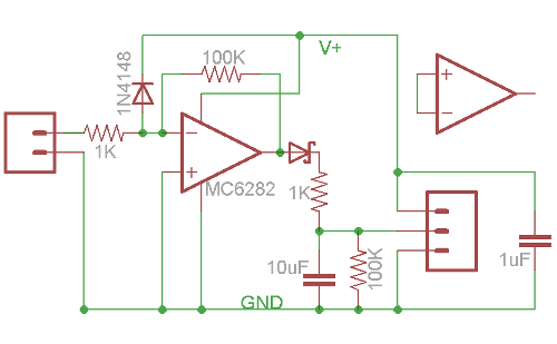 The MCP6282 dual rail-to-rail opamp has become my goto part for such things, with a (single) supply voltage range of 2.2-6V. I only used one section, and basically boosted the small sine wave out of the coil to a rail-to-rail square wave. Using a Shottky diode to
 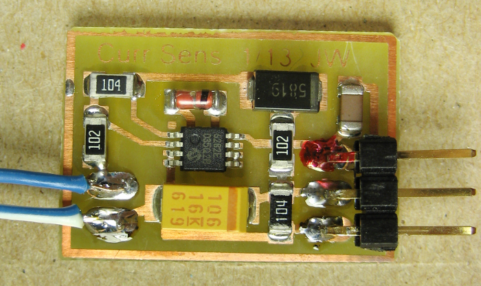 rectify it provides as high a DC level out as possible. The 1K in series with the output protects the opamp and allows it to drive an LED directly. The 100K/10μF time constant determines how long after power turns off the logic signal remains high. I put a 1uF decoupling cap across the supply for good measure. The odd diode from the input to V+ is input protection. There’s a clamp diode to ground on the chip, so between the two even some nasty spikes shouldn’t fry the opamp.
 For the proto coil, I soldered some wire from stranded CAT 5 cable to the real winding and secured it to provide more robust connection. Here’s the coil and amp and a one-turn primary, ready to (be packaged up better to) sense when an appliance (my fridge) was running so the run times could be logged. There are more details on the logging (and the fridge coil cleaning that inspired the logging) here.
While this provides an acceptable signal for a fairly high impedance digital input on an Arduino, when I tried to run an LED with one as part of testing coils I wound at W88, the LED  flickered at 60Hz. The 10μF cap wasn’t enough to keep the LED on solid. Since one application is to drive the IR LED input of a solid state relay, and since there’s a second half of the MC6282, here’s a better schematic that should drive either an input pin or an LED. I think I can drop the ugly 10μF cap down to 1μF by only loading it with a voltage follower using that second opamp.
For the real world, mounting the coil to the PCB would probably make sense. That would make for a more robust assembly, and the coil wouldn’t need reinforced leads.
Transformerless power supply
For the SSR driver version, we don’t have low voltage DC available (but we don’t have any other possible references to ground/neutral, either). Since there’s no exposed wiring, this might be a good application for a transformerless power supply using a cap  to drop line voltage without dissipating any power. I’ve never built one before, but the design is pretty straight forward. Here’s my simplistic starting point:
The 0.47μF cap presents about 5.6KΩ of reactance at 60Hz. At 120VAC, that would allow a maximum of about 20mA to flow. Since the rectifier/cap only charge on every other half cycle, the max DC current it can supply is more like 10mA. That’s perfect for running our 6282 and the LED in a SSR. (I measured about 3mA of current through that LED at 5V.)
(Design sanity power check: The zener keeps the voltage across (the diode and) the big cap to a max of ~5V. It conducts in its forward direction on the half cycles the supply cap isn’t charging. Thus it conducts ~20mA on the half cycles when the top wire is negative, and (20mA – DC output current) on the others. Worst case (after the big cap is charged and no current is being drawn) it conducts 20mA on both half cycles. With 5V across it one way and 0.7V the other, it must dissipate ~110mW – no problem for a half-watt zener. So this whole supply should produce very little heat.)
Update 1/24/18: The transformerless supply above is really too simplistic. While it’s fine to use a cap as the main voltage drop, there should be a series resistor at least to limit inrush current. It would also be very appropriate to have an X or Y rated cap designed to fail open. A fuse, or at least fusible resistor would be appropriate. While I’m not going for X caps for a TL supply I’m designing into another project, and I couldn’t easily source fusible resistors, I did get some ~1A picofuses, which I’ll use.
Putting it all together to make something useful
I breadboarded the supply, and it seems to work. I just need to lay out a PCB with the supply, the updated signal amp and a place to mount (hot glue) the coil.
But while I was thinking about what size handy box I’d need to fit the PCB/coil, SSR, outlets and maybe some switches, some little sanity birdie whacked me upside the head, bringing me out of the OK-I-can-make-one-of-those-but-if-I-just-add-one-more-part-I could-make-it-do-even-more-cool-stuff death spiral.
The problem I was really trying to solve was eliminating the annoyance of having to make two motions to turn the belt sander on, then reach over to turn the vacuum on.  While a current sensor on the sander line would work fine, the real problem was that the two switches were a couple feet apart. If the switches were right next to each other and could be operated in one motion like this ->, the problem would go away. And I wouldn’t even have to make up a PCB or spend one of my $6 SSRs!
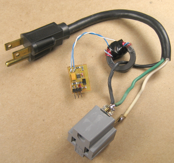
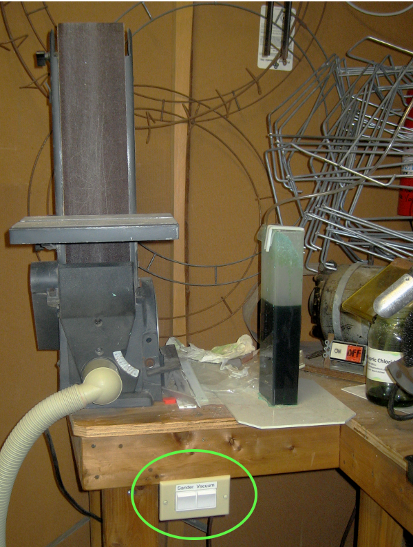 A couple of handy boxes back to back for the switches, outlets and a power cord pigtail, and here it is installed and working. Not the solution I expected when I started – but it fully meets the requirements. (Well, except for the part about finding a good excuse to make the current sensor/SSR thing.) I’m sure I’ll actually need a current sensed power switch for something else some day, and when I do I’ll have the design work already all done.
Update 6/15/13: Having used the twin-switch setup for a couple of months now, I have to say I love it. Turning both on is trivial, and when I just need the vacuum, the switch is right there and easy to use. I wish I’d done it years ago.
Hello! It’s actually MCP6282 Op Amp. As for the simplistic power supply, there are no means to limit the current spike when you connect it to the AC source. I tried this with the LEDs and they failed after several on-off cycles.
Hi Alex,
Thanks for the correction on the opamp.
Your comment/experience with spike protection is very interesting. (Sorry to hear about the LEDs. We all leave a string of fried parts behind us, each with a little lesson attached. Thanks for letting one of my lessons be from a part in your garbage can!)
Many of the transformerless designs I found split the voltage-dropping task between a small cap and a series resistor. I wonder if the reason was exactly to provide some spike protection? In the simple schematic above, it looks like there are 2 things that might help with spikes.
The first is the zener itself. Of course it depends on the surge capability of that device. I’m sure a big enough spike could exceed what the diode could handle – but if that happens the supply is blown anyway.
But how about the big cap directly across the output? I’d expect (per spike) the voltage to be split across the small cap/big cap divider in (inverse) proportion to their values, with the small cap charging first to take most of the voltage. With the 200:1 values shown, I’d expect about 199/200 of the voltage across the small cap. With say a 1000V spike, that should leave only about 5V across the big cap. Of course if it were already charged to 5V, the resulting 10V could blow downstream devices.
Now I’m really curious: When you blew out your LEDs, did you have a big cap across them? And did you have a zener?
Thanks!
Jim
Hi Jim!
No worries about those LEDs, they were kind of doomed. It actually happened a month or two ago, so obviously not your fault 🙂
I knew this cap solution is a hack and just wanted to see whether I can get away with it at all. The schematic was 3 of 5mm LED parallel and then 3 parallel to those but with opposite polarity. A cap (1uF or 0.47uF maybe?) and a resistor in series and it went into 220V 50Hz AC mains. What resistor it was I can’t remember, but some hundreds of Ohms likely.
First time on it was okay. Then I started to plug it in and out and those LEDs kept failing one by one. Besides, the resistor was getting hot so increasing the value wasn’t an option.
So this little experiment has kinda proved the point about it being a cheap hack that didn’t work.
You clearly have a point about adding a cap across the output. A rectifier bridge and a cap, yes. Maybe another time 🙂
I see a typical zener diode has a hefty surge capability. No comparison with that of those fragile LEDs.
Cheers,
Alex
Hi there Jim,
A very good idea of AC current sensing! Great job! I just stepped over it on hackaday.
As I am beginner on such topics, how would I need to change your transformerless power supply to support 220V?
Cheers,
J
A short calculation:
You need about 20mA. At 220V it gives:
R = 220/0.020 -> 11000 ohm.
then
C = 1 / (2 pi R F )
gives:
R = 11000 ohm
F = 50 Hz
C = 1 / ( 2 pi 11000 50 ) -> 29 microF
Closest standard value is 30 or 33 or … ?
Oups a little blooper! the capacitor should be
0.29 uF NOT 29 uF !
Pingback: Toroid winding cheat | Hackaday