
I’ve been working on two “3 volt” sound modules – a micro SD card module for the dollhouse and a from-scratch flash memory sampled sound playback device for the starter’s gun. Neither one actually works on 3.3V. So begins the tale.
 The Noisemakers
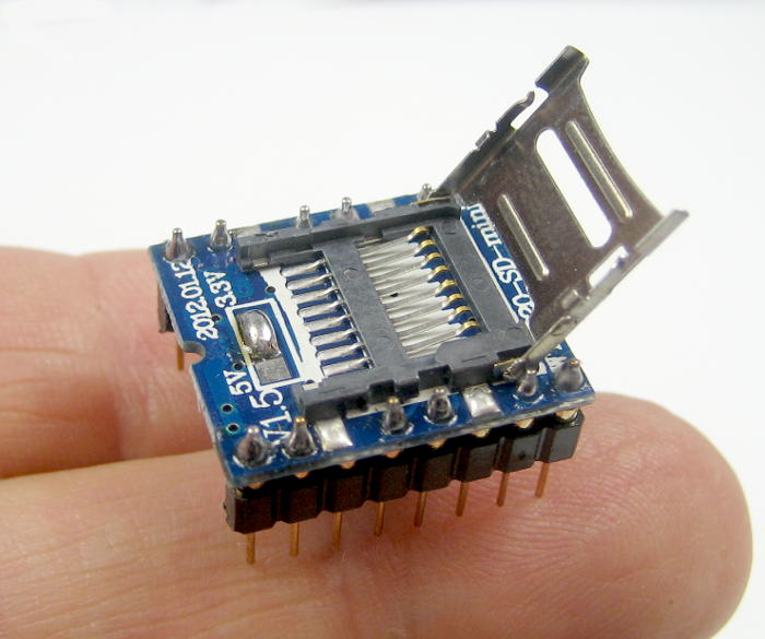
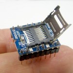
It started with the $4 cheap Chinese WTV020 micro SD based player module. The Ebay ad says it’s 5V compatible, but it isn’t. The details deserve their own separate post, but the bottom line is that I got it working on a fairly fully charged Li-ion battery.
(Li-ions and Lipos have become my bench supply of 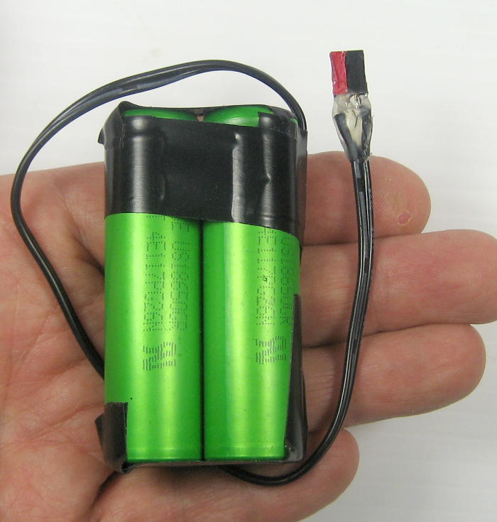 choice. They’re small and portable, and Arduinos and most other stuff
 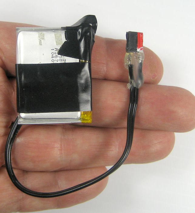 run happily on them. A favorite is this pair of 18650s (2P) from an old laptop battery. It’s over 3 amp-hours at 3.6V! But even a 300 mA-hr Lipo recycled from a Sansa recorder is very useful. Of course they’re nominally 3.6V, and up to 4.2V fully charged, so they’re really sometimes out of spec for many 3.3V devices.)
After some pass-fail testing with a real bench supply, I decided the module would run happily on 3.8 or 3.9V. But this was for the dollhouse, whose main power bus is 5V, so I’d need some kind of regulator. Unfortunately, 3.8V isn’t a common value. But I can make something.
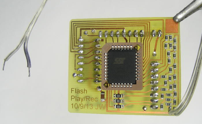 The second noisemaker was a 1Mbit SST39VF010 flash memory playing straight sound samples thru an R-2R ladder D/A. (Thanks to Workshop 88 for the donation of a strip of 4.7K 0805 SMT resistors off a reel of 6 zillion or something.) The chip is a 3.3V part to fit in with other 3V parts (like an XBee) in its device. While that also deserves its own post, I got the first player board up with a Diavolino (Duemilanove clone) running on 3.3V. I’ve had
 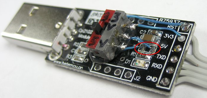 enough things that needed 3.3V that I have a couple of cheapie CP2102 USB-serial adapters wired to deliver 3.3V from their internal regulators to the 6-pin serial connector for Diavolinos. That all worked fine.
But to program the chip I needed more I/O lines than my 328Ps could provide. So I got a (clone) Mega2560, and made up a mini-shield for the memory 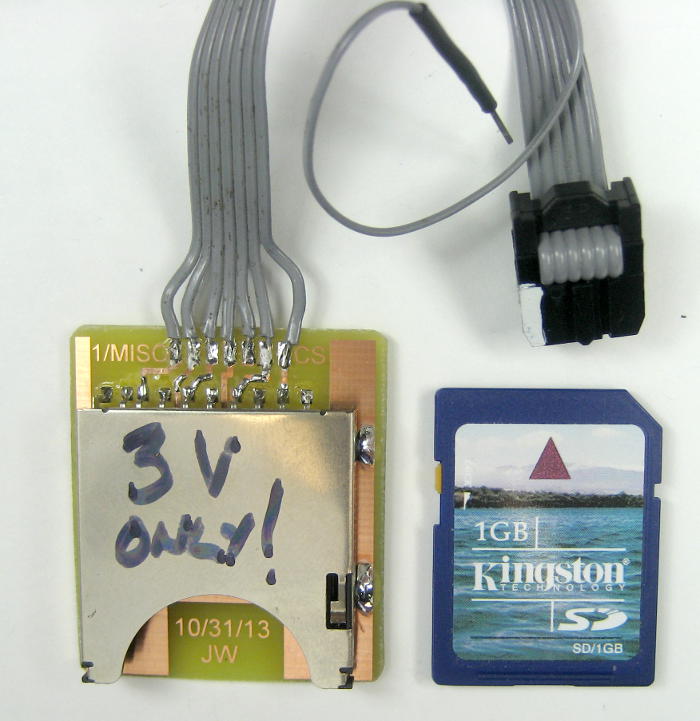 chip. (Picture at the end.) To get the sound samples to write to the memory, I made up a very simple SD card adapter (to plug into the ICSP header for SPI, plus a loose Chip Select). SD cards run on 3.3V, so that should all be good.
Unfortunately I had no way to run the Mega on 3.3V. Its on-board regulator properly provided 5V for this 16MHz device, so I couldn’t go in the barrel jack. The simplest way in was a USB-B cable with 3.3V on the power leads. I’ve built up a lot of strange adapters over the years, but not one of those. Fine – I can cut the cable and insert a regulator in line. Ugly, but it should work, and then I’ll have a way to run the Mega on 3.3V for future projects as well.
Two regulators
OK, I need two 3.xV regulators. I had some low dropout 3.3 volt LM1117-3.3 regulators. It’s a 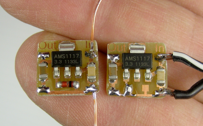 kludge, but putting a normal silicon diode (1N4148) in series with the ground lead to the regulator will boost the output voltage by 0.6-0.7V – just what I needed for the micro SD module. I made two copies of the diode-kludge PCB and jumpered across the diode on one for the Mega. The one with the diode measured about 3.9V, so it should work with the micro SD player; the one without measured 3.3V, as it should.
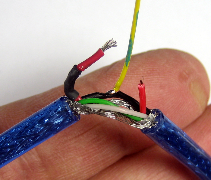 I cut a USB-B cable open, cut the red (+) wire, and got a tap off
 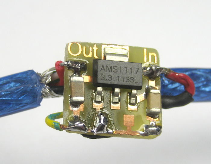 the black (-). I patched the new little 3.3V (no diode) regulator board inline, and sure enough it put out 3.3V. But understandably, the cable was really fragile feeling. So I reinforced the whole stretch of cable around the regulator by gluing a “splint” of heavy sheet
 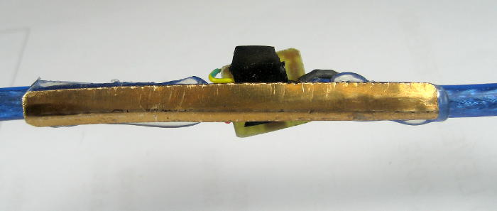 brass angle under the board. That’s at least sturdy enough to do some testing with. I plugged it into the Mega.
The power LED came on and it even seemed to load code, but it failed the code verify step. Now every 328P based Arduino I’ve tried runs fine on 3.3V – even though at 16MHz that supply voltage is out of spec. But this 2560 (or at least some part of its USB connection) wouldn’t. Yeah, I know it’s out of spec, but boo anyway. Now what?
I disconnected the two 3V parts (SD card and memory shield) from the Mega and plugged in a regular 5V USB cable. Of course it worked and loaded code fine. I unplugged the 5V cable, reconnected the 3V parts, and plugged in my 3.3V regulator USB cable. (The order matters!) It seemed to work. But my code, or the new hardware, or both didn’t work. While I could do the onerous connect/disconnect 3V/5V dance each time I wanted to load new code, even more worrying was that I wasn’t 100% sure the Mega was working perfectly. And that’s a horrible way to have to debug new code and hardware. Ugh. I wondered – might just a little more voltage help?
Well, there’s still a place laid out for a diode on the regulator board. While I wasn’t willing 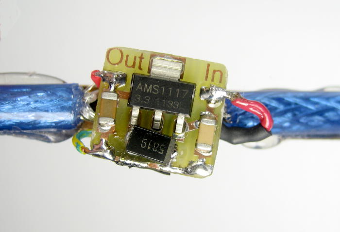 to go to the 3.9V a regular diode would produce, if I put a Shottky diode in maybe that extra couple of tenths of a volt would do the trick without blowing anything up. The Shottkys I had didn’t really fit, but I removed the jumper and finessed one in. It produced 3.5V. It’s worth a try.
And it worked! After some more adventures (including the fact 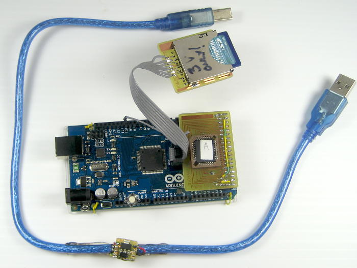 that the Mega uses pins 50-52 for SPI while I was using them for memory address lines, making it impossible to use the SD card and memory at the same time), I got both the code and the hardware working. Here’s the whole setup, including its hacked regulated cable.
Now that I can actually program sounds into the memory chips, I have to be able to get them out of that funny socket to move them to the player board. But now I have a tool for that 🙂 .